Washer HONDA CR-V 1997 RD1-RD3 / 1.G Owners Manual
[x] Cancel search | Manufacturer: HONDA, Model Year: 1997, Model line: CR-V, Model: HONDA CR-V 1997 RD1-RD3 / 1.GPages: 1395, PDF Size: 35.62 MB
Page 893 of 1395
Power Steering Gearbox
Reassembly (cont'dl
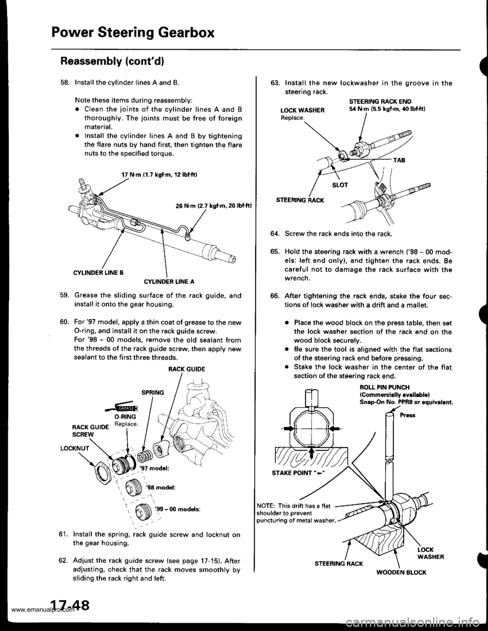
58. Installthe cylinder lines A and B
Note these items during reassembly:
. Clean the joints of the cylinder lines A and B
thoroughly. The joints must be free of foreign
material,
. lnstall the cylinder lines A and B by tightening
the flare nuts by hand first, then tighten the flare
nuts to the soecified torque.
CYLINDEF LINE A
Grease the sliding surface of the rack guide, and
install it onto the gear housing.
For'97 model, apply a thin coat of grease to the new
O-ring, and install it on the rack guide screw.
For'98 - 00 models. remove the old sealant from
the threads of the rack guide screw. then apply new
sealant to the first three threads.
-6rO-RING
nlcr cutDE R"Pl""u'
SCREW
LOCKNUT
37 model:
60.
ot.
38 model:
Install the spring, rack guide screw and locknut on
the gear housing.
Adjust the rack guide screw (see page 17,15). After
adjusting, check that the rack moves smoothly by
sliding the rack right and left.
17 N.m 11.7 kgd.m, 12lbf.ttl
26 N.m {2.7 kgl.m, 20
RACK GUIOE
17-48
STEERING RACK
(
63. Install the new lockwasher in the groove in the
steering rack.
LOCK WASHERReplace.
STEERING RACK ENO54 N.m (5.5 kgf.m,40 lbtftl
64.
STEERING
Screw the rack ends into the rack.
Hold the steering rack with a wrench ('98 - 00 mod-
els: left end only), and tighten the rack ends. Be
careful not to damage the rack surface with the
wrench.
After tightening the rack ends, stake the four sec-
tions of lock washerwith a drift and a mallet.
. Place the wood block on the press table, then set
the lock washer section of the rack end on the
wood block securely.
. Be sure the tool is aligned with the flat sections
of the steering rack end before pressing.
. Stake the lock washer in the center of the flat
section of the steering rack end,
ROLL PIN PUNCH
lCommorcially.Y.il.blelSnap-On No. PPR8 or oquival.nt.
NOTE: This drift has a flatshoulderto preventpuncturing of metal washer.
WOODEN BLOCK
www.emanualpro.com
Page 915 of 1395
Disassembly/ Inspection
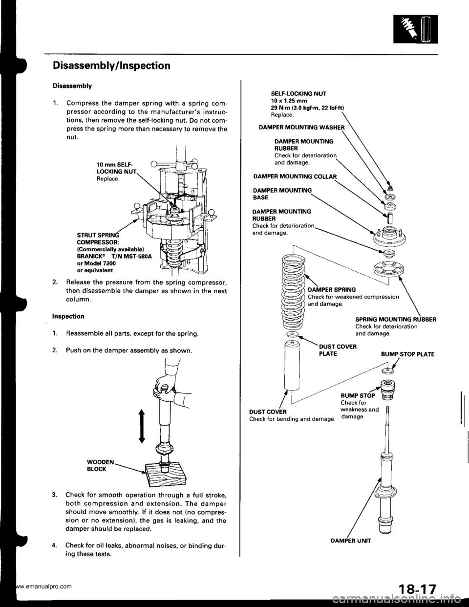
Disass.mbly
1. Compress the damper spring with a spring com-
pressor according to the manufacturer's instruc-
tions, then remove the self-locking nut. Do not com-press the spring more than necessary to remove the
nur.
10 mm SELF-LOCKINGReplace.
STRUTCOMPRESSOR:lComm6rcially availablo)BRANICK@ T/N MST-580Aor Mod6l 7200or equivalent
Release the pressure from the spring compressor,
then disassemble the damper as shown in the next
cotumn.
Inspection
1.Reassemble all parts, except for the spring.
Push on the damper assembly as shown.
Check for smooth operation through a full stroke,
both compression and extension. The damper
should move smoothly. lf it does not (no compres-
sion or no extension), the gas is leaking, and the
damper should be replaced.
Check for oil leaks, abnormal noises, or binding dur-
ing these tests.
2.
29 N.m (3.0 kgl.m,22lbtftlReplace.
DAMPER MOUNTING WASHER
DAMPER MOUNTING
SELF-LOCKING NUT10 x 1.25 mm
RUBBERCheck forano oamage.
DAMPER MOUAMNG COLLAR
DAMPER MOUNTINGBASE
DAMPER MOUNTINGRUBBERCheck for det€riorationano oamage.
BUMP STOP PLATE
DUSTCheckfor bending and damage.
..rgBUMPSTOP g
weakness anddamage,
SPRING MOUNTING
www.emanualpro.com
Page 916 of 1395
Front Damper
Reassembly
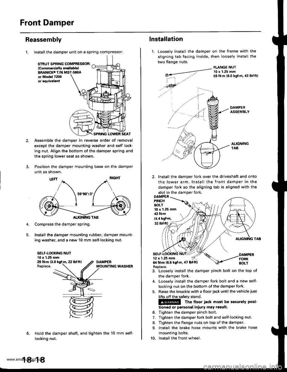
1. Install the damper unit on a spring compressor.
STRUT SPflNG COMPBESSOR:lcomm.rcillly .vrilrble)BRANICKC T/N MST.sEOAor Mod.l 7200or oquivtla
SPRING LOWER SEAT
Assemble the damper in reverse order of removal
except the damper mounting washer and self lock-
ing nut. Align the bottom of the damper spring and
the spring lower seat as shown.
Position the damper mounting base on the damper
unit as shown.
Compress the damper spring,
Install the damper mounting rubber, damper mount-
ing washer, and a new 10 mm self-locking nut.
SELF-LOCKING NUT10 x 1.25 mmZt N.m 13.0 kgf.m, 22 lbf.ft)Replace.
Hold the damper shaft, and tighten the
locking nut.
DAMPERMOUNfING WASHER
18-18
10 mm self-
1.
lnstallation
Loosely install the
aligning tab facing
two flange nuts.
damper on the frame with
inside, then loosely install
FLANGE NUT
the
tne
-__---a-"- 10 x 1.25 mmg*- 59 N.m {5.0 kgt m, 43 tbf.ftl
| -,./.46- --...
./ -4 A-
DAMPERASSEMBLY
ALIGNINGTAB
2, Install the damper fork over the driveshaft and onto
the lower arm. Install the front damper in the
damper fork so the aligning tab is aligned with the
slot in the damDer fork,
3. Loosely install the damper pinch bolt on the top of
the damper fork.
4. Looselv install the damper fork bolt and a new self-
locking nut on the bottom of the damper fork.
5. Raise the knuckle with a floor iack until the vehicle just
lifts off the safetv stand.
The lloor iack must b€ socurely posi-
tioned or personal iniury may result.
6. Tighten the damper pinch bolt.
7. Tighten the damper fork bolt and self-locking nut.
8. Tighten the flange nuts on top of the damper.
9. Install the brake hose mounts with the brake hose
mounting bolts.
10. Installthe front wheel.
10 x 1.25 mmil3 l+m
{4.4 kgf'm,
Replace.
www.emanualpro.com
Page 922 of 1395
Rear Damper
Disassembly/lnspection
Disassembly
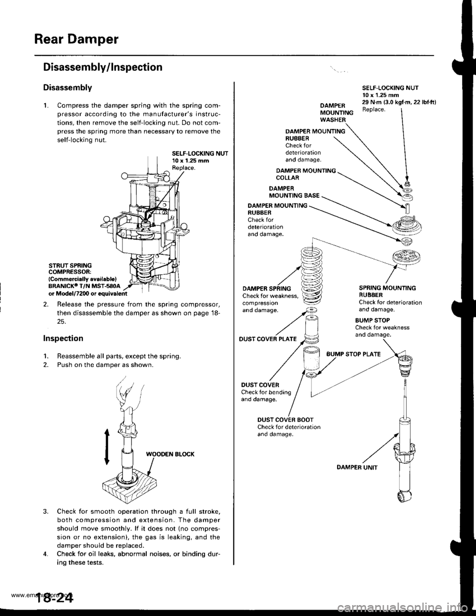
L Compress the damper spring with the spring com-
pressor according to the manufacturer's instruc-
tions, then remove the self-locking nut. Do not com-
press the spring more than necessary to remove the
self-locking nut.
SELF-LOCKING NUT10 x 1.25 mmReplace.
STRUT SPRINGCOMPRESSOR:lCommercirlly avaihblo)BRANICKO I/N MSI-580Aor Mod6l/7200 or equivalent
2. Release the pressure from the spring compressor,
then disassemble the damper as shown on page 18-
25.
Inspection
1. Reassemble all parts, except the spring.
2. Push on the damper as shown.
3.
WOODEN ELOCK
Check for smooth operation through a full stroke,
both compression and extension. The damper
should move smoothly. lf it does not (no compres-
sion or no extension), the gas is leaking, and the
damper should be replaced.
Check for oil leaks, abnormal noises, or binding dur-
ino these tests.
4.
SELF-LOCKING NUT10 x 1.25 mm
OAMPERMOUNTINGWASHER
29 N.m {3.0 kgf.m, 22 lbf.ft)Beplace.
OAMPER MOUNTINGRUBBERCheck fordeteriorationano oamage.
DAMPER MOUNTINGCOLLAR
DAMPERMOUNTING BASE
DAMPER MOUNTINGRUBBERCheck fordeteriorationano oamage.
'"dd"^.s"'
//F,
DAMPERCheck for weakness,compressron
DUST COVER PLATE
DUST COVERCheck for bendingand damage.
SPRING MOUNTINGRUBBERCheck Ior deteriorationand damage.
BUMP STOPCheck for weaknessano oamage.
DUST COVEN BOOTCheck for deterioralionano oamage.
BUMP STOP PLATE
DAMPER
www.emanualpro.com
Page 923 of 1395
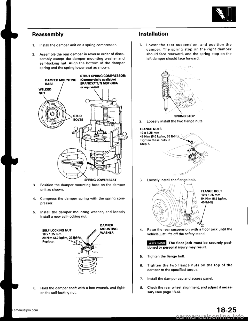
Reassembly
1.Install the damper unit on a spring compressor,
Assemble the rear damper in reverse order of disas-
sembly except the damper mounting washer and
self-locking nut. Align the bottom of the damper
spring and the spring lower seat as shown.
2.
DAMPER MOUNNNG
STRUT SPBING COMPRESSOR:(Commorcislly !v.ilablelBRANICKC T/N MST.s8OA
3.Position the damper mounting base on the damper
unit as shown.
Compress the damper spring with the spring com-
pressor.
Install the damper mounting washer, and loosely
install a new self-locking nut.
SELF.LOCKING NUT10 x 1.25 mm29 N.m (3.0
Replace.
Hold the damper shaft with a hex wrench, and tight-
en the self-locking nut.
1.
lnstallation
Lower the rear suspenston,
damper. The spring stop on
should face rearward, and the
left damper should face forward.
and position the
the right damper
sprang stop on the
SPRING STOP
2. Loosely install the two flange nuts.
FLANGE NUTS10 x 1.25 mm . .:{9 N.m 15.0 kgf.m, 36 lbtft}- :',,-rigf't"n if'"""_nrr. in ----.-*
qla^ 7Step 7.
3. Loosely install the flange bolt.
FLANGE EOLT10 x 1.25 mm54 N.m 15.5 kgt.m,40 tbI.ft)
6.
7.
8.
Raise the rear suspension with a floor jack until the
vehicle just lifts off the safety stand.
@ The floor iack must be securely posi-
iioned or personal iniury may result.
Tighten the flange bolt.
Tighten the two flange nuts on the top of the
damper to the specified torque.
Install the damper cap and access panel.
Check the rear wheel alignment. and adjust if neces-
sary (see page 18-4).
18-25
www.emanualpro.com
Page 935 of 1395
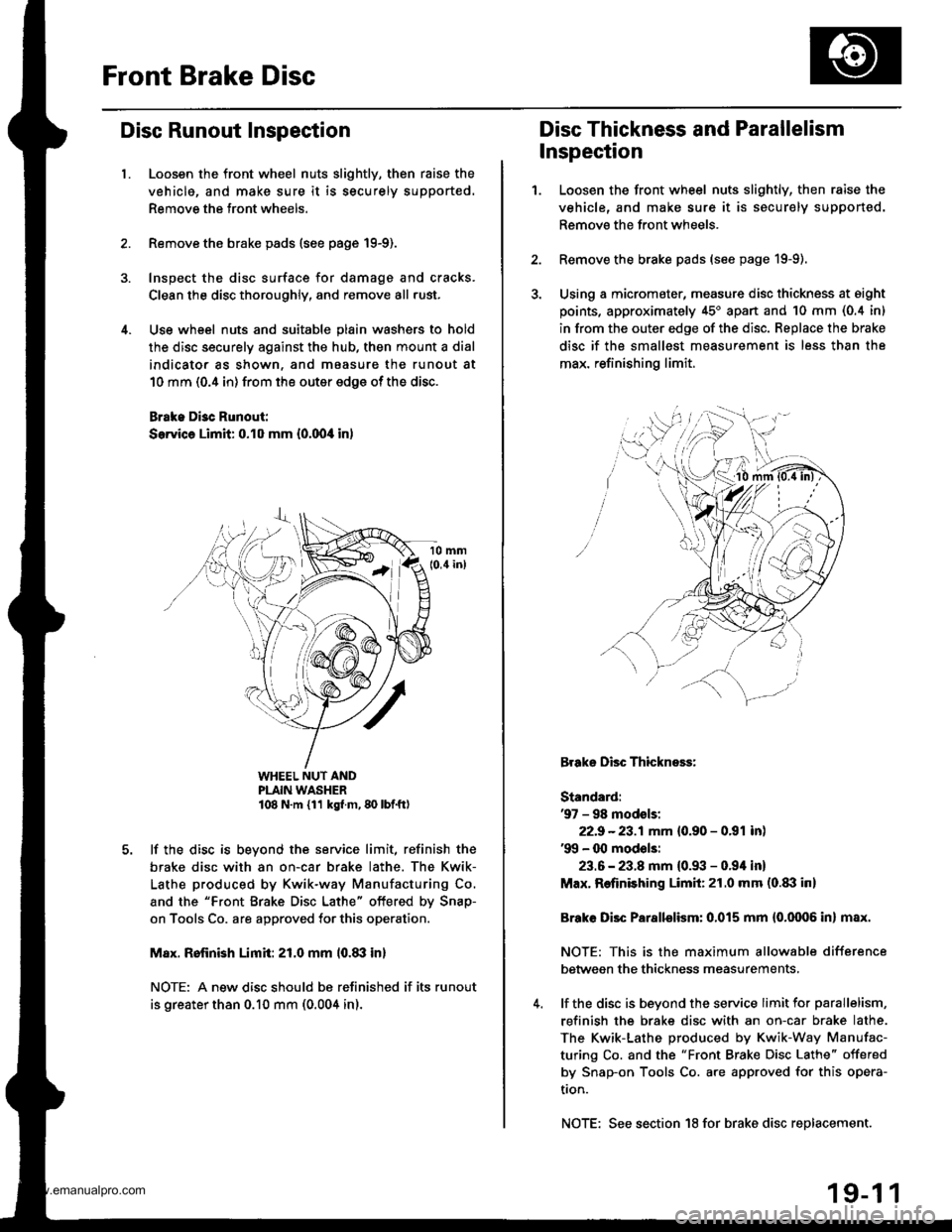
Front Brake Disc
Disc Runout Inspection
l.Loosen the front wheel nuts slightly, then raise the
vehicle, and make sure it is securely supported.
Remove the front wheels.
Remove the brake pads {see page 19-9).
Inspect the disc surface for damage and cracks.
Clean the disc thoroughly, and remove all .ust.
Use wheel nuts and suitable plain washers to hold
the disc securely against the hub, then mount a dial
indicator as shown, and maasure the runout at
10 mm (0.4 in) from the outer edge of the disc.
Brake Di3c Runout:
Service Limit: 0.10 mm {0.00,0 in)
WHEEL NUT ANDPLAIN WASHER108 N.m {11 kg{ m, 80 lbf.ft)
lf the disc is beyond the service limit, refinish the
brake disc with an on-car brake lathe. The Kwik-
Lathe produced by Kwik-way Manufacturing Co.
and the "Front Brake Disc Lathe" offered by Snap-
on Tools Co. are approved for this operation.
M8x. Rofinish Limit: 21.0 mm l0.8il in)
NOTE: A new disc should bs refinished if its runout
is greater than 0.10 mm (0.004 in).
Disc Thickness and Parallelism
Inspection
1.Loosen the front wheel nuts slightly, then raise the
vehicle, and make sure it is securely supported.
Remove the front wheels.
Remove the brake pads (see page 19-9).
Using a micromater, measure disc thickness at eight
points, approximately 45'apan and 10 mm (0.4 in)
in from the outer edge of the disc. Replace the brake
disc if the smallest measurement is less than the
max. refinishing limit.
Brake Disc Thickness:
Standard:'97 - 98 modsls:
22.9 -23.1mm {0.90 - 0.91 inl'99 - 00 mod€ls:
23.6 - 23.8 mm {0.93 - 0.94 in}
Max. Refinishing Limit:21.0 mm (o.txl in)
Brake Disc Parallelism: 0.015 mm {0.0006 in} max.
NOTE: This is the maximum allowable difference
between the thickness measurements,
lf the disc is beyond the service limit for parallelism,
refinish the brake disc with an on-car brake lathe.
The Kwik-Lathe produced by Kwik-Way Manufac-
turing Co. and the "Front Brake Disc Lathe" offered
by Snap-on Tools Co. are approved for this opera-
tron.
NOTE: See section 18 for brake disc replacement.
19-1 1
www.emanualpro.com
Page 936 of 1395
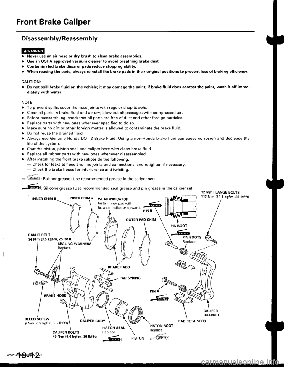
Front Brake Caliper
Disassembly/Reassembly
. Never use an air hose or dry brush to clean brake assemblies.
. Use an OSHA approved vacuum cleaner to avoid breathing brake dust.
. Contaminated brake discs or pads reduce stopping ability.
. When reusing the pads, always reinstallthe brake pads in their original positions to prevent loss ol braking efficiency.
CAUTION:
. Do not spill brake fluid on the vehicle; it may damage the paint; if brake fluid does contact the paint, wash it off imme-
diatelY with water.
NOTEI
. To prevent spills, cover the hose joints with rags or shop towels.
. Clean all pans in brake fluid and air dry; blow out all passages with compressed air.
. Before reassembling, check that all parts are free of dust and other foreign particles.
. Replace parts with new ones whenever specified to do so.
. Make sure no dirt or other foreign matter is allowed to contaminate the brake fluid.
. Do not reuse the drained fluid.
. Always use Genuine Honda DOT 3 Brake Fluid. Using a non-Honda brake fluid can cause corrosion and decrease the
life of the system.
. Coat the piston, piston seal, and caliper bore with clean brake fluid.
. ReDlace all rubber oarts with new ones whenever disassembled.
. After installing the front brake caliper do the following.- Check for leaks at hose and line joints and connections, and retighten if necessary.- Check the brake hoses for interference and twistinq.
SHIM
12 mm FLANGE BOLTS113 N.m (11.5 kgtm,83lbf.ftlINNER
ft
il1
#
\i
#
PIN B
OUTER PAO SHIM
PAD SPRING
IPIN BOOT
-Cr
SEALING WASHERSReplace.4dd*
ERAKE PADS
'f,-rre
/ tto*l "o"\
t@I
/\'
sLreo 6cnew \I N m 10.9 kStm, 6.5 lbnft)
\
6-
>PIN A
-6, {
CALIPER BOOY
CALIPER EOLTS49 N.m {5.0 kgl.m, 36lbf.ftl
PISTON AOOTReplace.
"..-a=a-...,--"sEqriPISTON
t".:jil,,.'.1!!!!9!il: Rubber grease (Use recommended grease in the caliper set)
irf"i:;;T::fl,-J'I",0 .@
--6, Silicone grease (use recommended seal grease and p,n grease in the caliper set)
INNER SHIM BWEAB INDICATOR
EANJO BOLT34 N.m {3.5 kgf m,25 lblftl
PISTON SEALReplace.
AFACKET
19-12
PAD RETAINERS
www.emanualpro.com
Page 942 of 1395
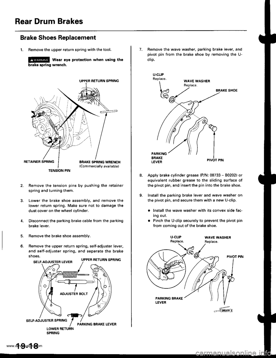
Rear Drum Brakes
Brake Shoes Replacement
1. Remove the upper return spring with the tool.
l@ w€ar eye protestion when using the
brske spring wrench.
RETAINER SPRINGBRAKE SPRING WBENCH{Commerciallv available)
Remove the tension pins by pushing the retainer
spring and turning them.
Lower the brake shoe assembly, and remove the
lower return spring, Make sure not to damage the
dust cover on the wheel cylinder,
Disconnect the parking brake cable from the parking
brake lever.
Remove the brake shoe assembly,
Remove the upper return spring, self-adjuster lever,
and self-adjuster spring, and separate the brake
shoes.
TENSION PIN
5.
o.
SELF.ADJUSTER LEVER UPPER RETURN SPRING
19-18
7. Remove the wave washer, parking brake lever. and
pivot pin from the brake shoe by removing the U-
cliD.
BRAKE SHOE
Apply brake cylinder grease (P/N: 08733 - 80202) or
equivalent rubber grease to the sliding surface of
the pivot pin, 8nd insert the pin into the brake shoe.
Install the parking brake lever and wave washer on
the pivot pin, and secure them with a new U-clip.
. lnstall the wave washer with its convex side fac-
Ing our.
. Pinch the U-clip securely to prevent the pivot pin
from coming out of the brake shoe.
U.CLIPReplace.
\\
w
U-CLIPReplace.WAVE WASHERReplace.
www.emanualpro.com
Page 946 of 1395
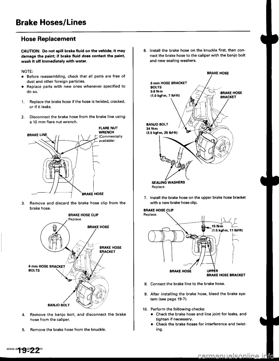
Brake Hoses/Lines
Hose Replacement
CAUTION: Do not spill brak€ fluid on the vehicl€; it m8y
damage th€ paint; if brak€ lluid doos contact tho paint,
wash it off immediately with water.
NOTE:
. Before reassembling, check that all pans are free of
dust and other foreign particles.
. Replace parts with new ones whenever specified to
qo so,
Replace the brake hose ifthe hose is twisted, cracked.
or if it leaks.
Disconnect the brake hose from the brake line using
a 10 mm flare nut wrench.
'1.
FLARE NUTWRENCH(Commercially
available)
BRAKE HOSE
Remove and discard the brake hose cliD from the
brake hose.
Remove the banjo bolt, and disconnect the brake
hose from the calioer.
5. Remove the brake hose from the knuckle.
19-22
6. Install the brake hose on the knuckle first, then con-
nect the brake hose to the caliper with the banjo bolt
and new sealing washers.
6 mm HOSE BRACKETEOLTS9.8Nm(1.0 kgf.m,7 lbf.ftlBRAKE HOSE
BANJO BOLT34 N.m
13.5 kgf.m, 25 lbl.ftl
SEALING WASHERSHeplace.
7. Installthe brake hose on the upper brake hose bracket
with a new b.ake hose clip.
Replace.
BRAKE HOSE ARACKET
Connect the brake line to the brake hose.
After installing the brake hose, bleed the brake sys-
tem (see page '19-7).
Perform the following checks;
. Check the brake hose and line joint for leaks, and
tighten if necessary.
. Check the brake hoses for interference and twist-
Ing
1 tbtftl
F
)
/
8.
9.
www.emanualpro.com
Page 982 of 1395
Body
Bumpers
Front Bumper Removal and
fnstaflation .........20-72
Rear Bumper Removal and
fnstaflation .........20-74
'Dashboard
lnstrument Panel Removal and
lnstallation .........20-47
Driver's Dashboard Lower Cover and
Knee Bolster Removal and
Installation .........20-48
Glove Box Removal and
lnstallation .........20-49
Center Pocket Removal and
lnstallation .........20-49
Center Dashboard Lower Cover
Removal and lnstallation ............ 20-50
Center Panel Removal and
lnstallation .........20-50
Power Window Switch Removal and
lnstallation .........20-51
Center Air Vent Removal and
lnstallation .........20-51
Side Air Vent Removal and
fnstallation .........20-52
Side Defogger Trim Removal and
fnstallation .........20-52
Dashboard Removal and
lnstallation .........20-53
Dashboard Frame Replacement ..... 20-55
Doors
Component Location Index
Front Door ,,...,,,,20-2
Rear Door ...........20-4
Tailgate Door ................................ 20-6
Fenderwell
Front Wheelwell Protector
Replacement .....20-89
Inner Fender Replacement .,.....,.,.... 20-89
Rear Wheelwell Protectol
Replacement .....20-90
Fuel Pipe Protector Replacement ... 20-90
Rear Air Outlet Replacement .......... 20-91
*Frame Repair Chart .............................. 20-106
Front Grille
Repf acement .........20-77
Glass
Component Location Index ............ 20-29
Hood
Replacement ......,,,20-75
Adjustment ............20-76
*lnterior Trim
Component Location Index ............ 20-40
Mirrors
Component Location Index .........,,, 20-26
Moldings
Roof Molding Replacement ............ 20-84
Door Moldings Replacement .......... 20-85
Openers
Component Location Index ............ 20-92
Rear Hatch Glass
Replacement .........20-74
Disassembly and Reassembly ........ 20-79
Adiustment ............20-81
Rear Weatherstrip Replacement .... 20-83
Seats
Component Location Index ............ 20-56
Side Sill Panel
Repfacement .........20-87
Spare Tire Cover
Emblem Installation ........................ 20-88
Sub-frame ..................20-104
Wiper/Washer
Component Location lndex ,,,,,....... 20-97
www.emanualpro.com