Washer HONDA CR-V 1997 RD1-RD3 / 1.G Workshop Manual
[x] Cancel search | Manufacturer: HONDA, Model Year: 1997, Model line: CR-V, Model: HONDA CR-V 1997 RD1-RD3 / 1.GPages: 1395, PDF Size: 35.62 MB
Page 1040 of 1395
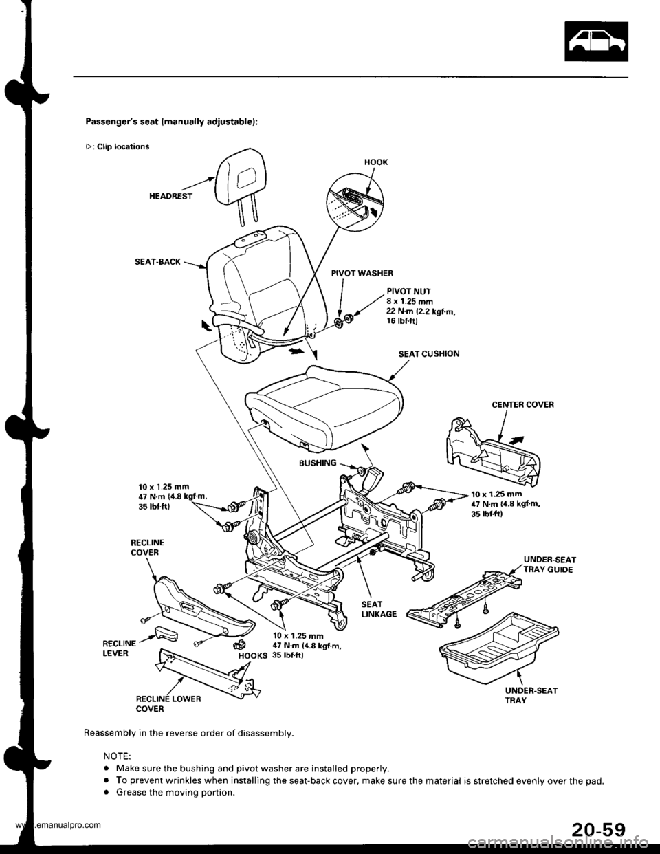
Passenger's seat (manually adiustablel:
>: Clip locations
HEADREST
SEAT.BACK
10 x 1.25 mm
PIVOT WASHER
PIVOT NUT8 x 1.25 mm22 N.m 12.2 kgl..n,16 tbt.ftl
SEAT CUSHION
CENTER COVER
BUSHING
COVER
Reassembly in the reverse order of disassembly.
NOTE:
. Make sure the bushing and pivot washer are installed properly.
. To prevent wrinkles when installing the seat-back cover, make sure the. Grease the moving portion.
'10 x 1.25 mm47 N.m {4.8 kgf m,
35 rbl.ft)
UNDER-SEATTRAY GUIDE
,U N.m 14.835 rbt.ft)
dHOOKS
10 x 1.25 mm17 N.m {4.8 kgl.m,35 tbf.ft)
HOOK
material is stretched evenly over the pad.
www.emanualpro.com
Page 1046 of 1395
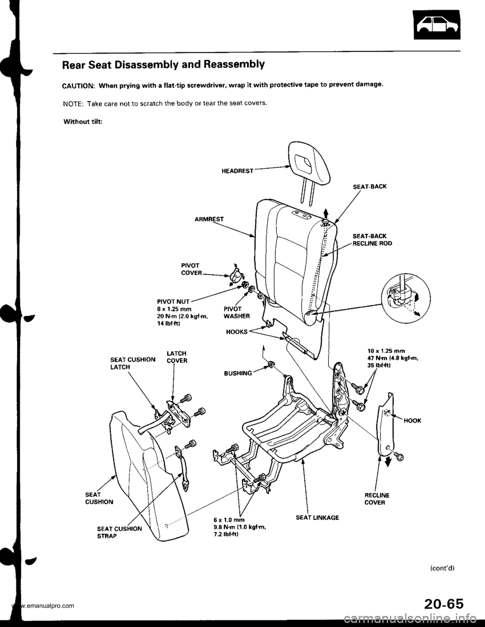
Rear Seat Disassembly and Reassembly
CAUTION: When prying with a flat-tip screwdriver, wrap it with protective tape to prevent damage.
NOTE: Take care not to scratch the body or tear the seat covers.
Without till:
SEAT.AACKRECLINE ROD
PIVOTCOVER
PIVOT NUT8 x 1.25 mm20 N.m 12.0 kg{.m.14 tbf.ftlWASHER
HOOKS
5x1.0mm9.8 N'm (1.0 kgf.m,7 .2 tbl.ltl
(cont'd)
20-65
SEAT-BACK
SEAT CUSHIONLATCH
SEATCUSHION
SEAT CUSHIONSTRAP
SEAT LINKAGE
www.emanualpro.com
Page 1047 of 1395
Seats
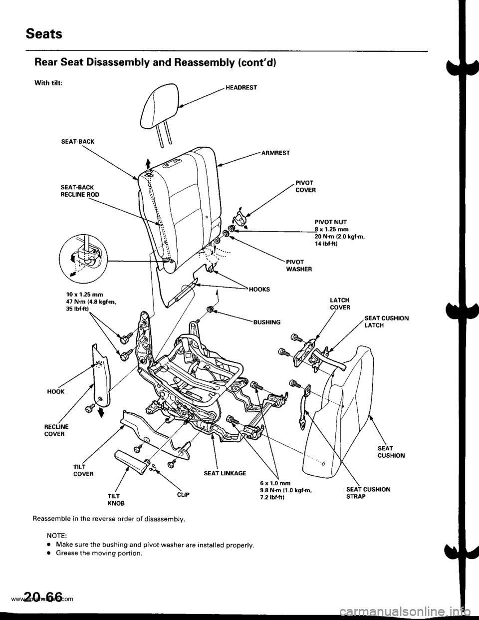
Rear Seat Disassembly and Reassembly (cont'd)
with tilr:
SEAT.BACKRECLINE ROO
10 x 1.25 mm47 N.m {4.8 kgfn,35 tbtft)
PIVOT NUTx 1.25 mm20 N{n (2.0 kgt.m,14 tbt-fr)
I-ATCHCOVER
SEAT CUSHIONLATCH
SEATCUSHION
SEAT LINKAGE
T;LT CLIP
KNOB
Reassemble in the reverse order of disassembly.
NOTE:
. Make sure the bushing and pivot washer are installed properly.. Grease the moving portion.
6x1.0mm9.8 N.m {1.0 kgf.m,7.2 tbf.ftl
SEAT CUSHIONSTRAP
20-66
SEAT-BACK
www.emanualpro.com
Page 1050 of 1395
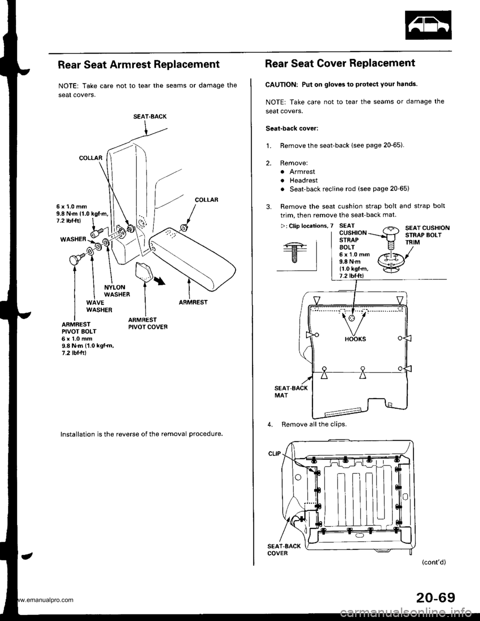
Rear Seat Armrest Replacement
NOTE: Take care not to tear the seams or damage the
seat covers.
COLLAR
COLLAR6x1.0mm9.8 N.m {1.0 kgf.m,7.2 rbr.ft)
WASHER
NYLONWASHER
VEARMRESTWASHER
ARMRESTPIVOT BOLT6x1.0mm9.8 N.m (1.0 kgt.m,7.2lbllll
lnstallation is the reverse of the removal procedure.
SEAT.BACK
Rear Seat Cover Replacement
CAUTION: Put on gloves to protect your hands.
NOTE: Take care not to tear the seams or damage the
seal covers.
Seal-back cover:
Remove the seat-back {see page 20-65).
Remove:
a Armrest
. Headrest
. Seat-back recline rod (see page 20-65)
Remove the seat cushion strap bolt and strap bolt
trim, then remove the seat-back mat.
L
2.
"'---.' t.-r" t-- i,': "" '
4. Remove all the clips.
(cont'd)
20-69
www.emanualpro.com
Page 1056 of 1395
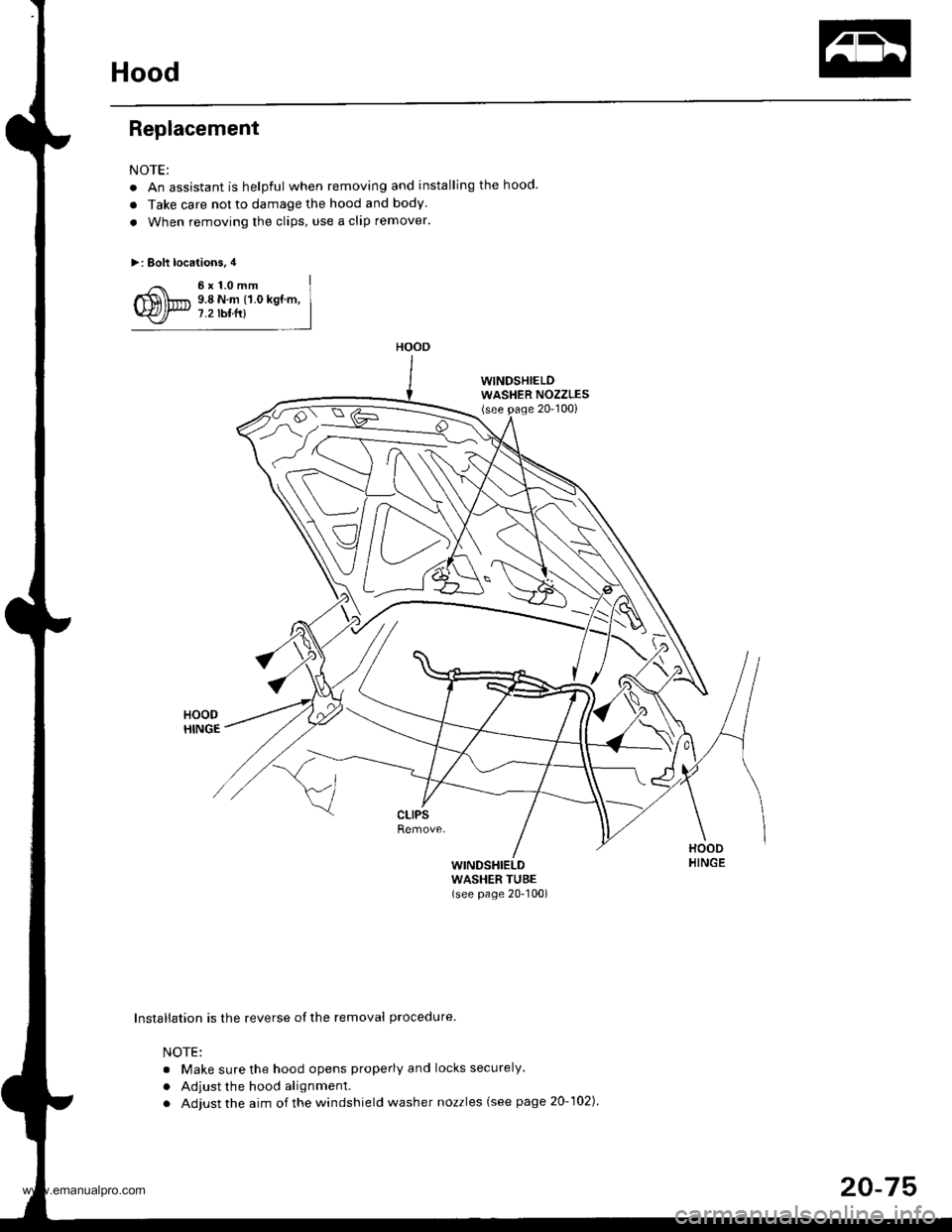
Hood
Replacement
NOTE:
. An assistant is helpful when removing and installing the hood.
a Take care not to damage the hood and body
. When removing the clips, use a clip remover.
>: Bolt locations, 4
6x1.0mm9.8 N.m {1.0 kgt.m,7.2 tbtfr)
WINDSHIELDWASHER NOZZLES(see page 20-100)
G
{
\HOODHINGEWINDSHIELDWASHER TUBE(see page 20-100)
Installation is the reverse of the removal procedure
NOTE:
. Make sure the hood opens properly and locks securely.
. Adjust the hood alignment.
. Adjust the aim of the windshield washer nozzles (see page 20-102)
HOOD
20-75
www.emanualpro.com
Page 1059 of 1395
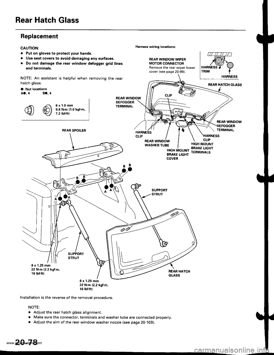
Rear Hatch Glass
Replacement
CAUTION:
. Put on gloves to protecl your hands.
. Use seal covers to avoid damaging any surfaces.. Do not damage the rear window delogger grid lines
and terminals.
NOTE: An assistant is helpful when removing the rear
hatch glass.
a: Nul locationsAa.4 Ba.4
€ @ i!iff*-"-
Harnoss wiring locations:
REAR WINDOW WIPERMOTOR CONNECTORRemove the rear wiper lowercover (see page 20-99i.
HARNESS 'TRIM
.;=-
8 x 1.25 mm22 N-m l'2.2 kgl.m,'16 tbt fr)
8 x 1.25 mm22N.m l.2.2*ql.m,16 tbf.ft|
Installation is the reverse of the removal orocedure.
NOTE:
. Adjust the rear hatch glass alignment.
. Make sure the connector, terminals and washer tube are connected properly.
. Adjust the aim of the rear window washer nozzle (see page 20-103).
20-78
REAR SPOILER
'--
www.emanualpro.com
Page 1060 of 1395
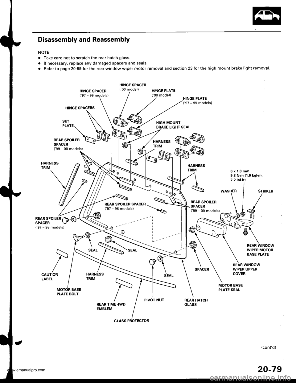
Disassembly and Reassembly
NOTE:
. Take care not to scratch the rear hatch glass.
. lf necessary, replace any damaged spacers and seals.
. Refer to page 20-99forthe rearwindowwiper motor removal and section 23 for the high mount brake light removal.
HINGE SPACERS
HINGE SPACEN('97 - 99 models)HINGE PLATE('00 model)
HARNESSTRIM
REAR SPOILEBSPACER{'99 00 models)
HARNESSTRIM6x1.0mm9.8 N.m {1.0 kgl.m,7.2 tbt.ft)
WASHERSTBIKER
s
R€AF WINDOWWIPER MOTORBASE PLATE
('97 - 98 models)
REAR SPOILERSPACER
CAUTIONLABEL
SEAL
REAR WINDOWWIPER UPPERCOVER
MOTOR BASEPLATE SEAL
PIVOT NUTFEAR TIME 4WDEMBLEM
{cont'd)
20-79
/=
GLASS PROTECTOR
www.emanualpro.com
Page 1078 of 1395
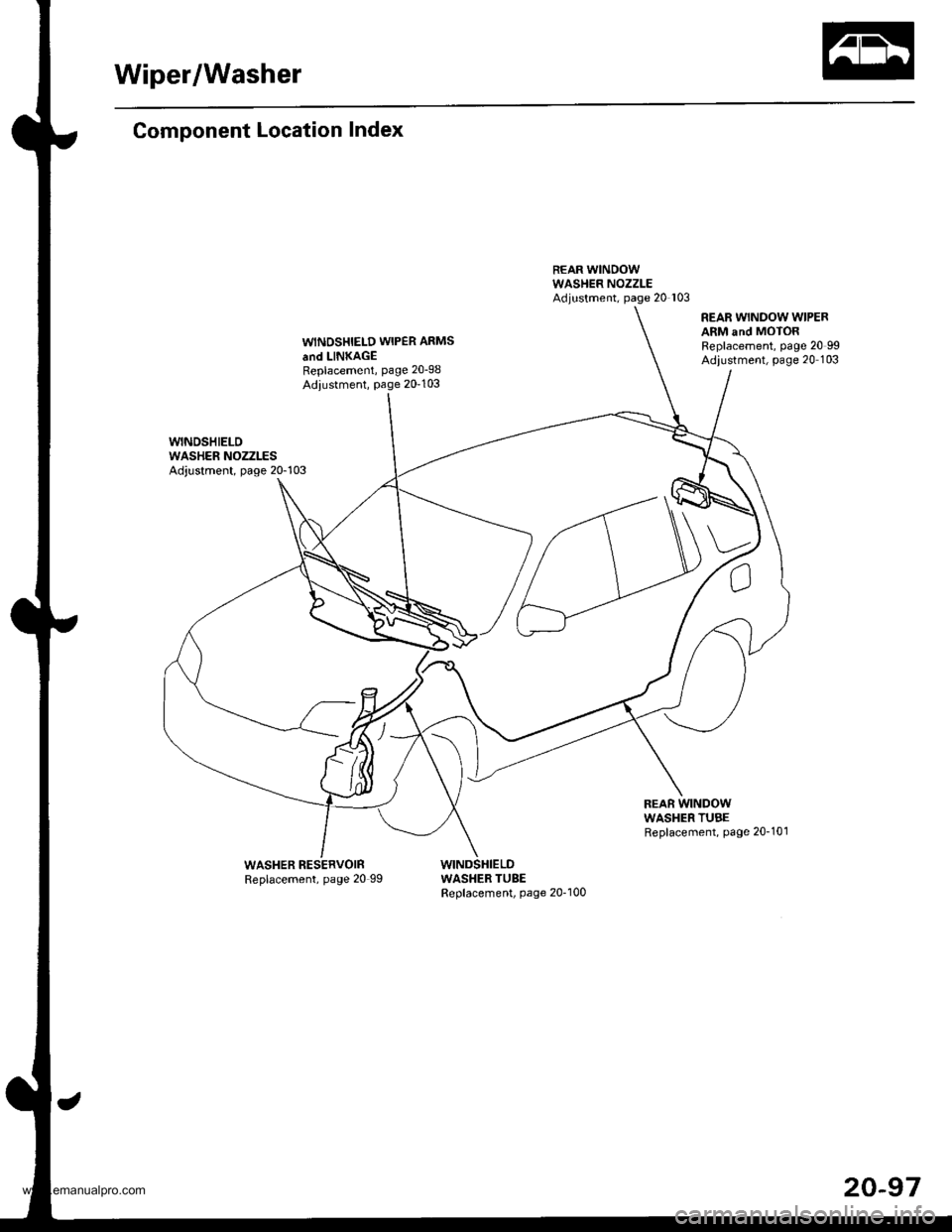
Wiper/Washer
Component Location Index
WINOSHIELD WIPER ARMS
and LINKAGEReplacement, page 20-98
Adiustment, Page 20-103
REAR WINDOW WIPERARM and MOTORReplacement, page 20 99Adiustment, page 20 103
WASHER RESERVOINReplacement, page 20 99WASHER TUBEReplacement, page 20-100
20-97
www.emanualpro.com
Page 1079 of 1395
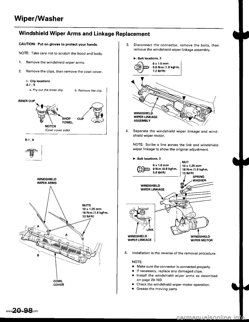
Wiper/Washer
Windshield Wiper Arms and Linkage Replacement
CAUTION: Put on gloves to protoct your hands.
NOTE: Take care not to scratch the hood and body.
1. Remove the windshield wiper arms.
2. Remove the clips, then remove the cowl cover.
>: Clip locationsA>.9
b. Remove the clip.
SHOPTOWEL
(Cowl cover side)
/G
"rr/ &
a. Pry out the anner clip.
INNER CLIP
B>.8
ql
WINDSHIELDWIPER ARMS
NUTS'10 x 1.25 mm18 N.m 11.8 kgf.m.13 tbf.ftl
COVER
20-98
3. Disconnect the connector, remove the bolts, then
remove the windshield wiper linkage assembly.
>: Boh locations,3
4. Separate the windshield wiper linkage and wind-shield wiper motor.
NOTE: Scribe a line across the link and windshieldwiper linkage to show the original adjustment.
>: Boh locations, 3
s}@
1ffi,
/Y{
/
' L|NK
WINDSHIELDWIPER LIN(AGEWIPER MOTOR
5. Installation is the reverse of the removal procedure.
NOTE:
. Make sure the connector is connected properly.. lf necessary. replace any damaged clips.. Install the windshield wiper arms as describedon page 20-103.
. Check the windshield wiper motor operation.. Grease the moving parts.
6x1.0mm9.8 N.m (1.0 kglm,7.2 tbt.fr)
6x1.0mm8 N.m 10.8 kgf.m,5.8 lbf.ftl
NUT10 x 1.25 mm18 N.m 11.8 kgf.m,13 tbf.ftlSPRINGWASHER
www.emanualpro.com
Page 1080 of 1395
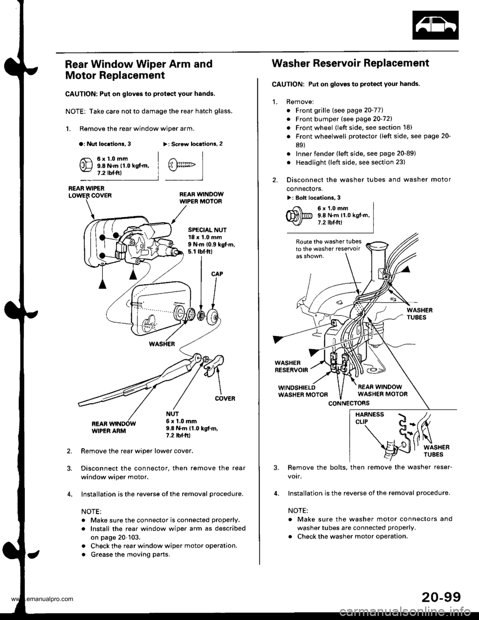
Rear Window Wiper Arm and
Motor Replacement
CAUTION: Put on gloves to protect your hands.
NOTE; Take care not to damage the rear hatch glass.
1. Remove the rear window wiper arm.
a: Nut loc.tion!, 3>: Scaow locationa, 2
REAR WINDOWWIPER MOIOR
REAR WIPERCOVER
REARWIPER ARM
6x1.0mm9.8 N.m 11.0 kgt'm,7.2 tbf.ftl
SPECIAL NUT18 x 1.0 mm9 N.m 10.9 kgt m,5. r tbt.ftl
NUT6x 1.0mm9.8 N.m {1.0 kgt.m,?.2 tbfftl
Remove the rear wiper lower cover.
Disconnect the connector, then remove the rear
window wiper motor.
Installation is the reverse of the removal procedure.
NOTE:
. Make sure the connector is connected properly.
. Install the rea. window wiper arm as described
on page 20-103.
. Check the rear window wiper motor operation.
. Grease the moving parts.
@rrc
Washer Reservoir Replacement
GAUTION: Put on gloves to protect your hands.
1. Remove:
. Front grille (see page 20-771
. Front bumper (see page 20-721
. Front wheel {left side, see section 18)
. Front wheelwell protector (left side, see page 20-
89)
. Inner fender (left side, see page 20-89)
. Headlight (left side, see section 23)
2. Disconnect the washer tubes and washer motor
connectors.
>: Bolt locations, 3
6x1.0mm9,8 N.m 11.0 kgt.m,7.2 tbt.ftl
Route the washer tubesto the washer teservoir
WASHERRESERVOIR
WINOSHIELOWASHER MOTON
CONNECTORS
3. Remove the bolts, then remove the washer reser-
votr,
4. Installation is the reverse of the removal procedure.
NOTE:
a Make sure the washer motor connectors and
washer tubes are connected properly.
. Check the washer motor operation.
HARNESS / tcLrP C-(fu
- S(ilq
s{J
l' wrsHER
20-99
www.emanualpro.com