relay HONDA CR-V 1997 RD1-RD3 / 1.G Workshop Manual
[x] Cancel search | Manufacturer: HONDA, Model Year: 1997, Model line: CR-V, Model: HONDA CR-V 1997 RD1-RD3 / 1.GPages: 1395, PDF Size: 35.62 MB
Page 1222 of 1395
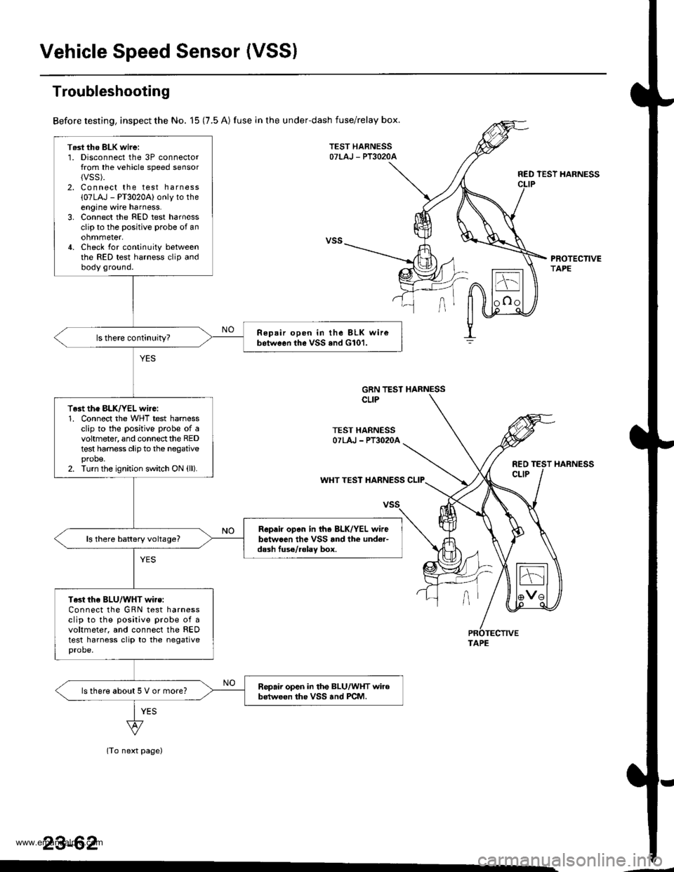
Vehicle Speed Sensor (VSSI
T6st tho BLK wirei1. Disconnect the 3P connectorfrom the vehicle speed sensor{VSS).2. Connect the test harness
{07LAJ - PT3020A) only to theengine wire harness.3. Connect the FED test harnessclip to the positive probe of anohmmeter,4. Check for continuity betweenthe RED test harness clip andbody ground.
Repair open in the BLK wirebetwGon the vSS .nd G101.
T.st the BLK/YEL wire:1. Connect the WHT test harnessclip to the positive probe of avohmeter, and connect the REDtest harness clip to the negativeprobe.2. Turn the ignition switch ON (ll).
Rep.ir op.n in th. BLK/YEL wirebetwaen the VSS rnd the und6r-dash fuse/.6lav box.ls there battery voltage?
Test the BLU/WHT wi.s:Connect the GRN test harnessclip to the posilive probe of avoltmeter. and connect the REDtest harness clip to the negativeprobe.
Repair open in the BLU/WHT wirobstweon the VSS and PCM.ls there about 5 V or more?
Troubleshooting
Before testing, inspect the No. 15 (7.5 A) fuse in the underdash fuse/relay box.
TEST HARNESSOTLAJ - PT3O2OA
RED TEST HARNESS
PROTECTIVETAPE
GRN TEST HARNESSCLIP
TEST HARNESSOTLAJ - PT3O2OA
REOCLIPWHT TEST HARNESS CLIP
(To next page)
23-62
HARNESS
TAPE
www.emanualpro.com
Page 1224 of 1395
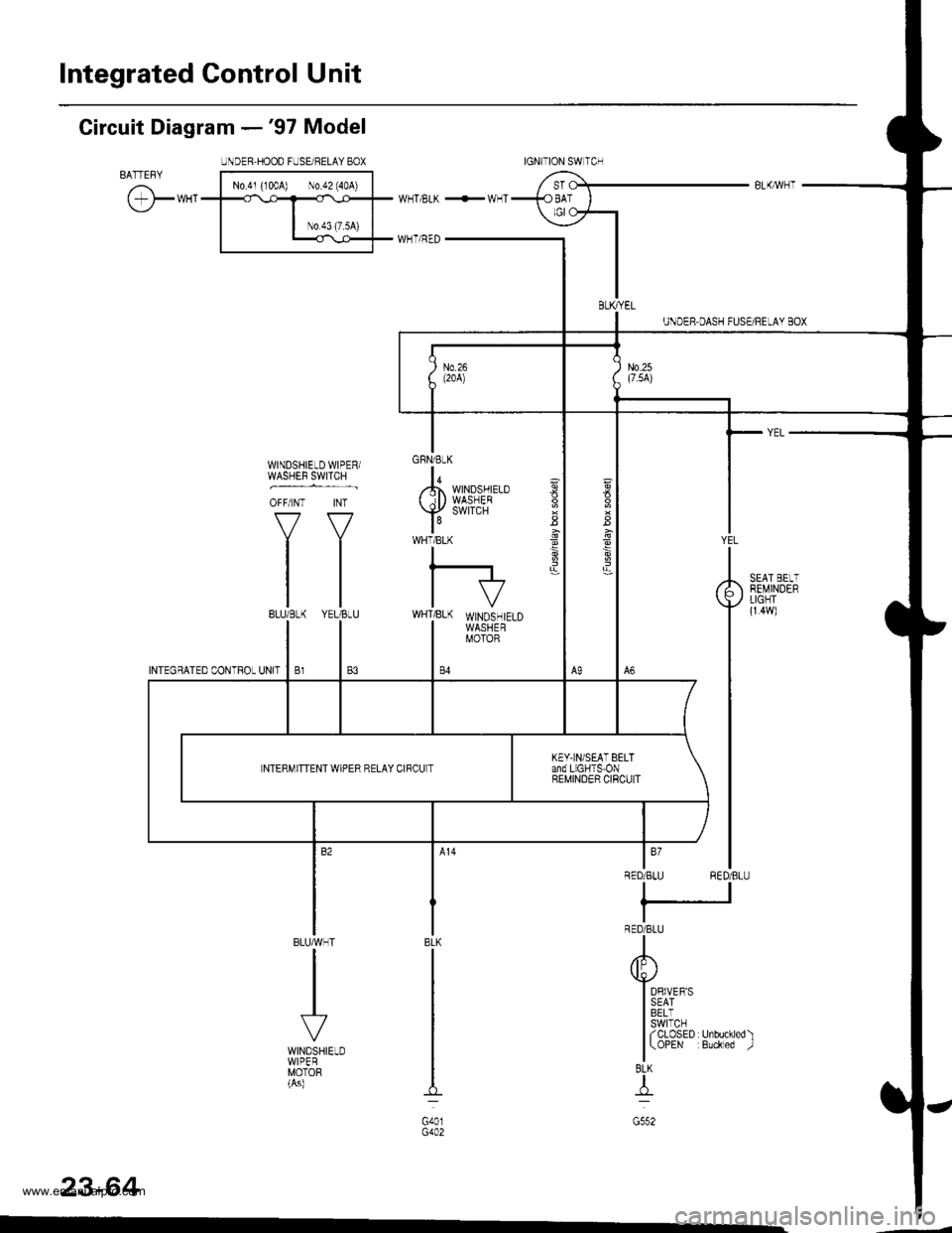
Integrated Gontrol Unit
Circuit Diagram -'97 Model
UNDER.HOOD FUSEi RELAY 8OXBATTEFYI No.4' {'004) \0.d2'40A) |
cr*"
l__*l;;T
w_T ELK +!v_T
I H-uTr.r--i=r-
GFNi BLK
lo,,.h WINDSHIELD( il) WASHEB
Y
SWITCH
WHTiBLK
I
l-IVWHT]BLK WINDSHIELDI WASHERI MOTOB
WINDSHIELD WIPER/WASHEF 9WTTCH ,
OFF/INT INT
VV
tltltl
tl
BLUMHT
VWINDSHIELDWIPERMOTOR(As)
ag
3
YEL
RED/BLU
DRIVER'SSEATBELTswtTcHf CLOSED r Unbuckled )(OPEN :Buckled -.1
BEMINDEBLIGHT(r 4w)
BLK
G401
BL(I-tr-l
G552
23-64
tGNITtON SW lCrl
BLKryEL
KEY.IN/SEAT BELTand LIGHTS-ONBEMINDER CIRCUITNTERMITTENT WIPER RELAY CIRCUlT
www.emanualpro.com
Page 1225 of 1395
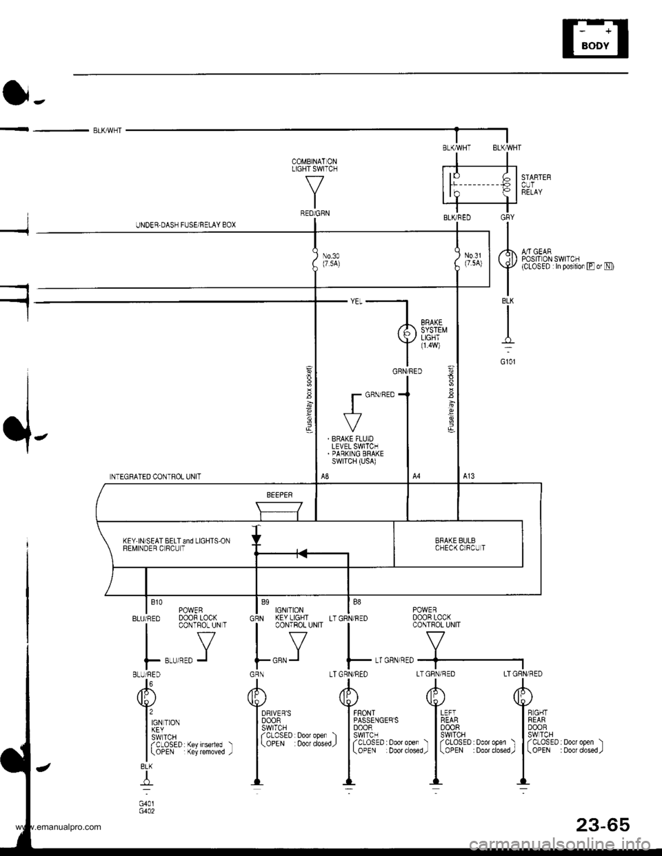
< - ELK/WHT
S'TARTEBCUTRELAY
A,/rGEARPOSrr 0N SWTTCH(CLOSED :ln postion Eor N)
COMBINATONLIGHT SWITCH
\-/
IRED/GRN
I
.l-
NTEGRATED CONTROL UNIT
POWERDOOR LOCKCONTROL UNIT
I B1o PowERBLU/RED DOOR LOCK
I CONTFOL UN T
IY
F r,r'tro J
BLUi RED
"l\
u/
llon. no*
155,1'*IaCLOSED Keylnseded
| \oPEN Key rcmoved
8LK
4
G40r
LTGRN/RED LTGRN/RED LTtl
/rh d[)v !s-l
I FFONT I LEFTI PASSENGEBS I REABI DOOR | 00ORoDen ) lSwlTcH I SWITCHdosedJ J f C-OSED : ooot ooer ) | f CLOSED : Door opel
| ( ooE Doot dosed,r | \oPEN Doo' closed
tl_L -._:-
1,,,,,"
Yilei'rGRN/RED
. BNAKE FLUIOLEVEL SWITCH.PARKING ERAKEswrTcH (usA)
A8
BRAKE BULBCHECKCIFCUTKEY.IN]SEAT BELT and LIGHTS'ONREMINDER C RCU T
23-65
www.emanualpro.com
Page 1226 of 1395
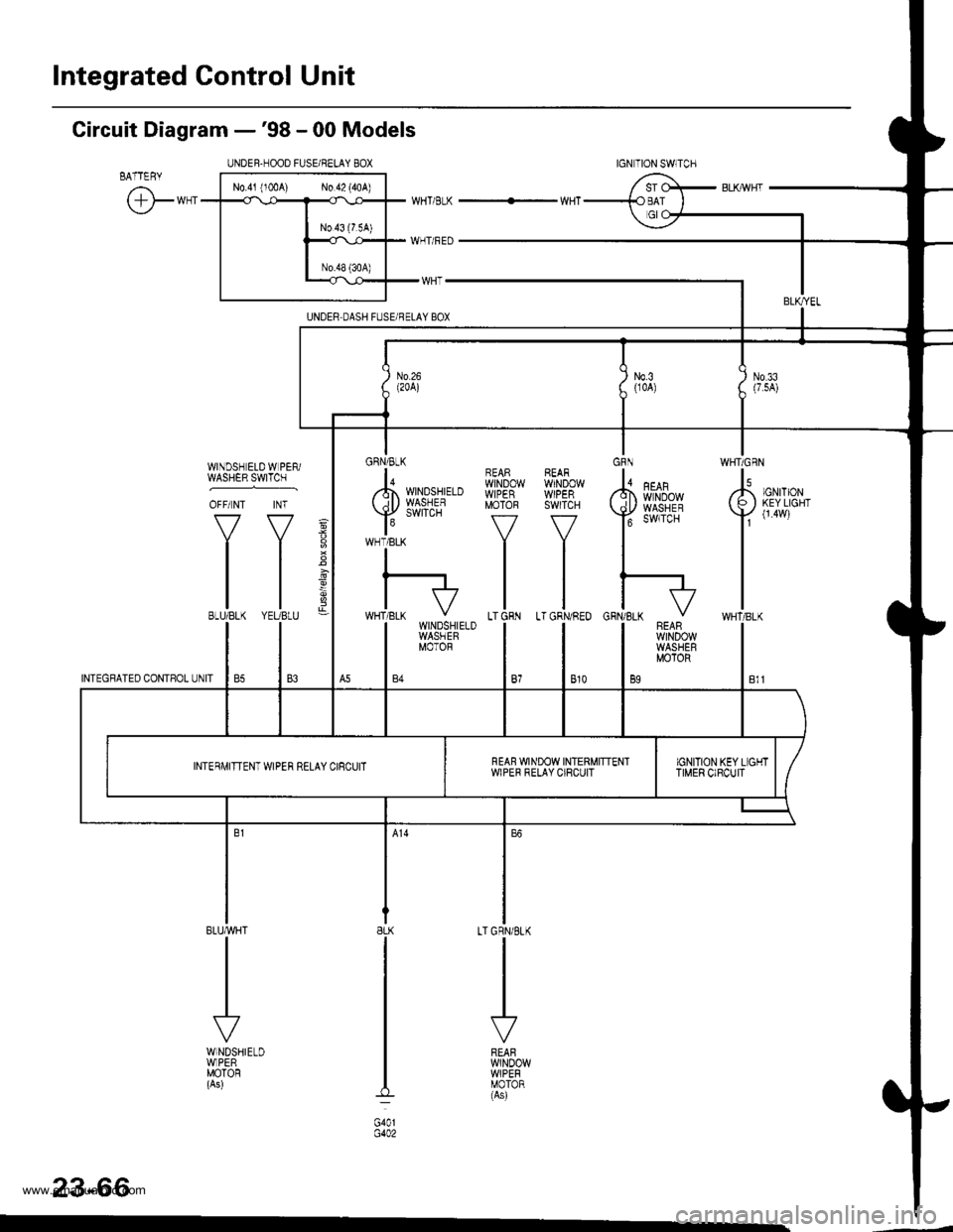
Integrated Control Unit
UNOER,HOOD FUSE/BELAY 8OX
N0.41 (100A) N0.42 (40A)
Circuit Diagram -'98 - 00 Models
EATTERY
@*"WHT/BLK -....+ WHT
WHT/RED
IJNDER DASH FUSEi BELAY BOX
WINDSH ELD W PER/gsHERlIrTcH .
OFF/ NT INT
f7 f7
tltl
tl
tlBLU/BLK YEUBLU
GRN/BLK
lo/.Fn WINDSHIELD( il) WASHEF
Y
SWITCH
WHT/BLK
REASWINDOWWIPERMOTOR
f7
ILT GRN
t,,
-9
INTEGFATED coNTsoL UNIT I 85 I 83
23-66
8LK
G401G402
WHT/BLKWINDSHIELDWASHEFMOTOR
INTERIT,IITTENT WIPER RELAY CIRCUITNEAF WINDOW INTERMITTENTWIPER RELAY CIRCUIT
www.emanualpro.com
Page 1228 of 1395
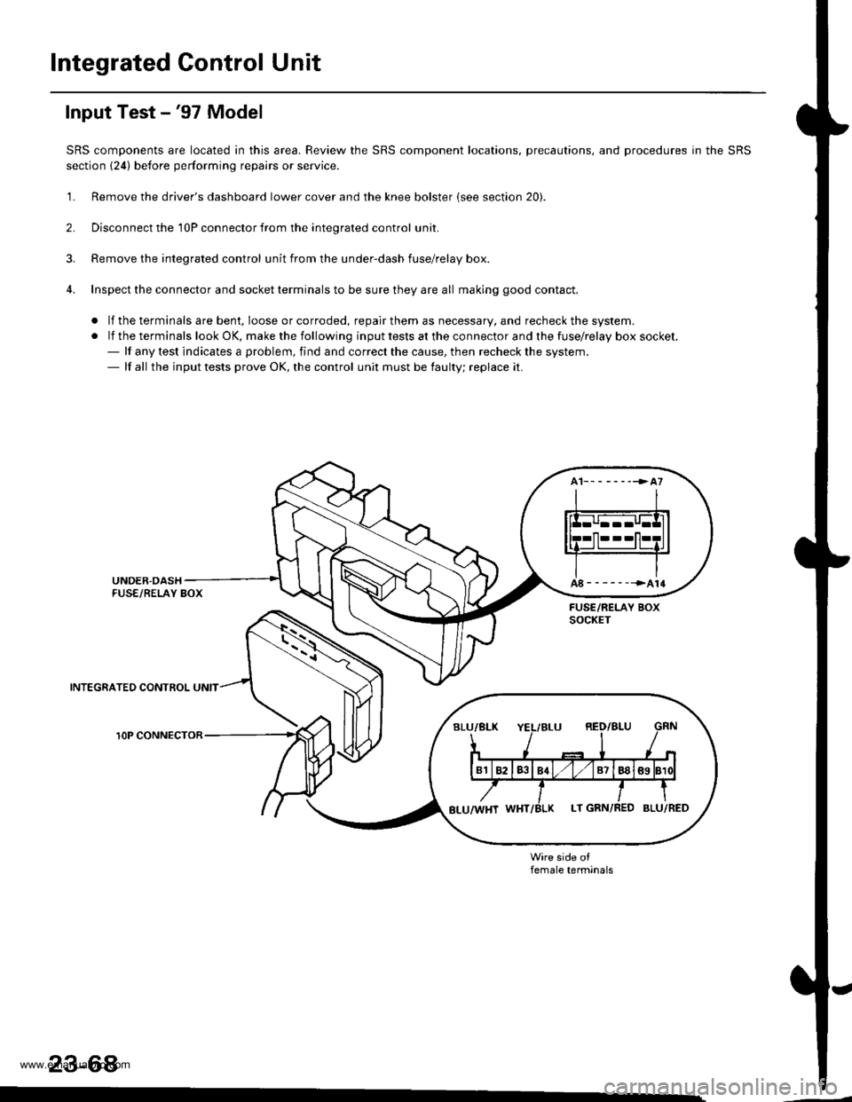
Integrated Gontrol Unit
Input Test -'97 Model
SRS components are located in this area. Review the SRS component locations, precautions, and procedures in the SRS
section {24) before performing repairs or service.
'1. Remove the driver's dashboard lower cover and the knee bolster (see section 20).
2. Disconnect the 'l0P connector from the inteorated control unit.
3. Remove the integrated control unit from the under-dash fuse/relay box.
4. Inspect the connector and socket terminals to be sure they are all making good contact.
. lf the terminals are bent, loose or corroded, repair them as necessary, and recheck the system.
.lftheterminalslookOK,makethefollowinginputtestsattheconnectorandthefuse\
/relayboxsocket.- lf any test indicates a problem, find and correct the cause, then recheck the system.- lf all the input tests prove OK, the control unit must be faulty; replace it.
INTEGRATEO CONTROL UNIT
rOP CONNECTOR
female terminals
23-68
www.emanualpro.com
Page 1229 of 1395
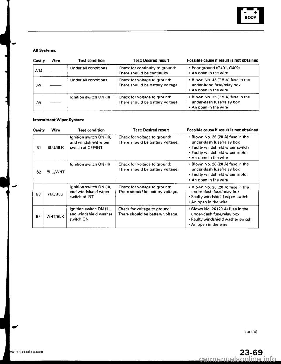
All Systems:
Cavity WireTest condition
Tost condition
Test: Desired r€sult
Test: Desired result
Intermittent Wipol System:
Cavity Wire
Possible cause if result is not obtained
Possible causs if result is not obtained
414Under all conditionsCheck for continuity to ground:
There should be continuity.
. Poor ground (G401, G402). An open in the wire
A9
Under all conditionsCheck for voltage to ground:
There should be battery voltage.
. Blown No. 43 (7.5 A) fuse in the
under-hood fuse/relay box. An open in the wire
A6
lgnition switch ON (ll)Check for voltage to ground:
There should be battery voltage.
. Blown No. 25 (7.5 A)fuse in the
underdash fuse/relay box. An open in the wire
B1BLU/BLK
lgnition switch ON (ll),
and windshield wiper
switch at OFF/lNT
Check for voltage to ground:
There should be battery voltage.
Elown No. 26 (20 A)fuse in the
under-dash fuse/relay box
Faulty windshield wiper switch
Faulty windshield wiper motor
An open in the wire
82BLUrur'HT
lgnition switch ON (ll)Check for voltage to ground:
There should be battery voltage.
Blown No.26 (20 A) fuse in the
under-dash fuse/relay box
Faulty windshield wiper motor
An open in the wire
B3YEVBLU
lgnition switch ON (ll),
and windshield wipe.
switch at INT
Check for voltage to ground:
There should be battery voltage.Blown No. 26 (20 A) tuse in theunder-dash fuselrefay box
Faulty windshield wiper switch
An open in the wire
B4WHT/BLK
lgnition switch ON (ll),
and windshield washer
switch ON
Check for voltage to ground:
There should be battery voltage.
Blown No. 26 (20 A) fuse in the
under-dash fuse/relay box
Faulty windshield washer switch
An open in the wire
(cont'd)
23-69
www.emanualpro.com
Page 1230 of 1395
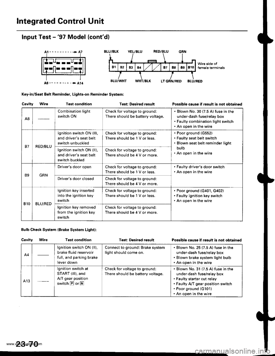
lntegrated Control Unit
Input Test -'97 Model (cont'd)
At----------+A7
Key-in/Seat Belt Reminder, Lights-on Remindor System:
Cavity WireTest conditionTest: Desired rosultPossible cause if re3ult is nol obtainod
Bulb Check System (Brake System Light):
Cavity WireTest conditionT6st: DGsirgd rosultPossible cause if resuh is not obtainod
23-70
A8
Combination light
switch ON
Check for voltage to ground:
There should be battery voltage.
Blown No.30 (7.5 A) fuse in the
under-dash fuse/relay box
Faulty combination light switch
An open in the wire
B7R ED/BLU
lgnition switch ON {lll.
and driver's seat belt
switch unbuckled
Check for voltage to ground:
There should be 1 V or less.
Poor ground (G552)
Faulty seat belt switch
Blown seat belt reminder light
bulb
An open in the wirelgnition switch ON (ll),
and driver's seat belt
switch buckled
Check for voltage to groundl
There should be 4 V or more.
B9GRN
Driver's door openCheck ior voltage to ground:
There should be 1 V or less.
. Faulty driver's door switch. An open in the wire
Driver's door closedCheck for voltage to ground:
There should be 4 V or more.
810BLU/RED
lgnition key insened
into the ignition key
switch
Check for voltage to ground;
There should be 1 V or less.
Poor ground (G401, G,[02)
Faulty ignition key switch
An open in the wire
lgnition key removed
trom the ignition key
swrtch
Check for voltage to ground:
There should be 4 V or more.
A4
lgnition switch ON { ll),
brake fluid reservoir
full, and parking brake
tever oown
Connect to ground: Brake system
light should come on.
Blown No. 25 (7.5 A) iuse in the
under-dash fuse/relay box
Blown brake system light bulb
An open in the wire
A13
lgnition switch at
START (lll), and
A/T gear position
switch E or E
Check for voltage to ground:
There should be battery voltage.
Blown No.31 (7.5 A) fuse in the
under-dash fuse/relay box
Faulty starter cut relay
Faulty A/f gear position switch
Poor ground (G101)
An open in the wire
www.emanualpro.com
Page 1231 of 1395
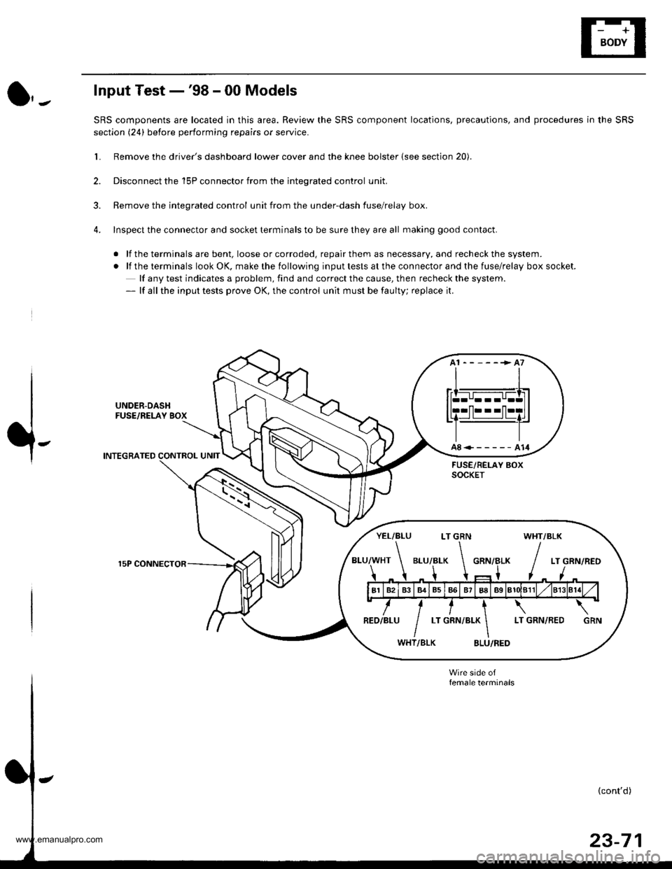
Input Test -'98 - 00 Models
SRS components are located in this area. Review the SRS component locations, precautions, and procedures in the SRS
section (24) before performing repairs or service.
L Remove the driver's dashboard lower cover and the knee bolster (see section 20).
2. Disconnect the 'l5P connector from the inteqrated control unit.
3. Remove the integrated control unit from the under-dash fuse/relay box.
4. Inspect the connector and socket terminals to be sure they are all making good contact.
. lf the terminals are bent, loose or corroded. repair them as necessary, and recheck the system.
.lftheterminalslookOK,makethefollowinginputtestsattheconnectorandthefuse\
/relayboxsocket.
lf any test indicates a problem, find and correct the cause, then recheck the system.- lf all the input tests prove OK, the control unit must be faulty; replace it.
UNDER-DASHFUSE/RELAY BOX
INTEGRATED CONTROL UNIT
15P CONNECTOR
A8<------A14
YEL/BLU LT GRN WHT/BLK
www.emanualpro.com
Page 1234 of 1395
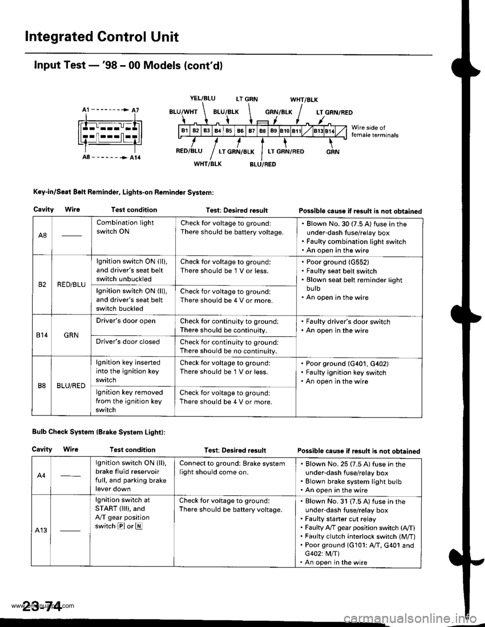
Integrated Control Unit
A1 --------> A7
Input Test -'98 - 00 Models (cont'dl
YEL/BLULT GRNWHT/BLK
GRN/BLKLT GRN/REO
Wire side offemale terminals
A8------->A14WHT/BLK
Key-in/Se8t Beft Reminder, Lights-on Remindol System:
BLU/RED
Cavity WireTest conditionTest: Desired resultPossible caus€ it result is not obtained
Bulb Check System lBrake System Lightl:
Cavity WireTest conditionTest: Desired resultPossible caus€ if result is not obtained
A4
lgnition switch ON (ll),
brake fluid reservoir
full, and parking brake
lever down
Connect to ground: Brake system
light should come on.
Blown No. 25 (7.5 A) fuse in the
under-dash fuse/relay box
Blown brake system light bulb
An open in the wire
A13
lgnition switch at
START ( lll), and
A,/T gear position
switch E or E
Check for voltage to ground:
There should be battery voltage.
Blown No. 31 {7.5 A) fuse in the
under-dash fuse/relay box
Faulty sta rter cut relay
Faulty A,/T gear position switch (A,/T)
Faulty clutch interlock switch (M/T)
Poor ground {G101: AfI. G401 and
G402: M/T)
An open in the wire
23-74
A8
Combination light
switch ON
Check for voltage to ground:
There should be battery voltage.
Blown No. 30 (7.5 A) fuse in the
under-dash fuse/relay box
Faulty combination light switch
An open in the wire
RED/BLU
lgnition switch ON ( ll),
and driver's seat belt
switch unbuckled
Check for voltage to ground:
There should be 1 V or less.
Poor ground {G552)
Faulty seat belt switch
Blown seat belt reminder light
bu lb
An open in the wirelgnition switch ON (ll),
and driver's seat belt
switch buckled
Check for voltage to ground:
There should be 4 V or more.
814GRN
Driver's door openCheck for continuity to ground:
There should be continuity,
. Faulty driver's door switch. An open in the wire
Driver's door closedCheck for continuity to ground:
There should be no continuity.
B8BLU/RED
lgnition key inserted
into the ignition key
swrtch
Check for voltage to ground:
There should be 'l V or less.
Poor ground (G401, G402)
Faulty ignition key switch
An open in the wire
lgnition key removed
from the ignition key
switch
Check for voltage to ground:
There should be 4 V or more.
www.emanualpro.com
Page 1236 of 1395
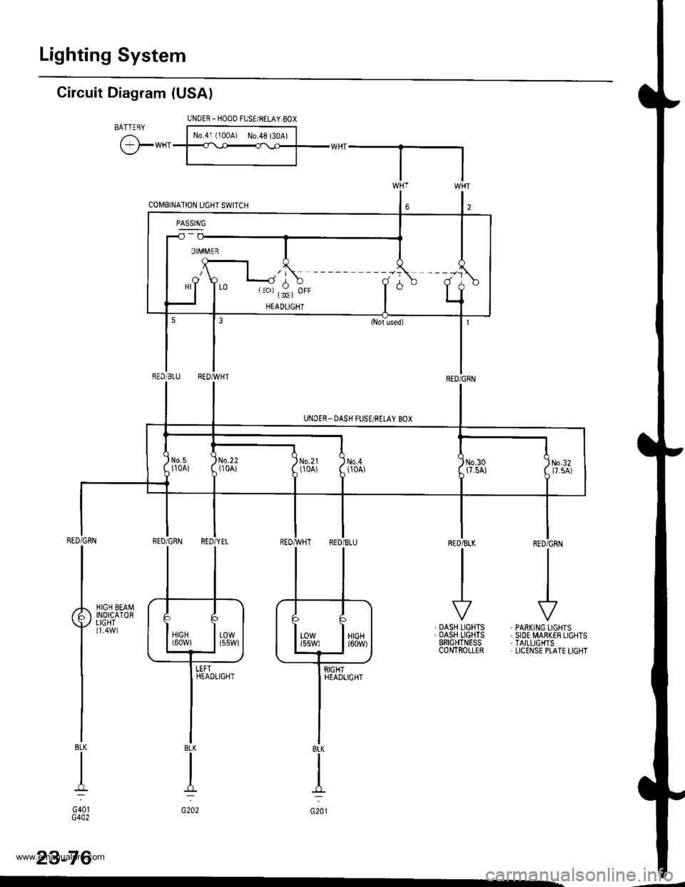
Lighting System
UNOER_HOOD FUSE/RELAY 8OX
Circuit Diagram (USAI
BATTERY
@**'
HIGH SEAI\4INDICATORLIGHT
BLK
I
G40lG4a2
lltl
tl
JJ
VV' DASH LIGHTS , PARKING LIGHTS. DASH LIGHTS . SIDE MARK€R LIGHTSBRIGHTNESS,TAILLIGHTSCOIVTROLLER . LICENSE PLATE TIGHT
rrf JLo -,.9,;,, T d
UNDER-DASH FUSEiREIAY BOX
No.5tl0AlNo.4{10A)N0.3017.5A)
I
li':,.^i
I
IflI
i,"dii Zt'"oll i
II
RED/BLURED'BLK
BLK
.&-
G202
23-76
www.emanualpro.com