TDC HONDA CR-V 1997 RD1-RD3 / 1.G User Guide
[x] Cancel search | Manufacturer: HONDA, Model Year: 1997, Model line: CR-V, Model: HONDA CR-V 1997 RD1-RD3 / 1.GPages: 1395, PDF Size: 35.62 MB
Page 124 of 1395
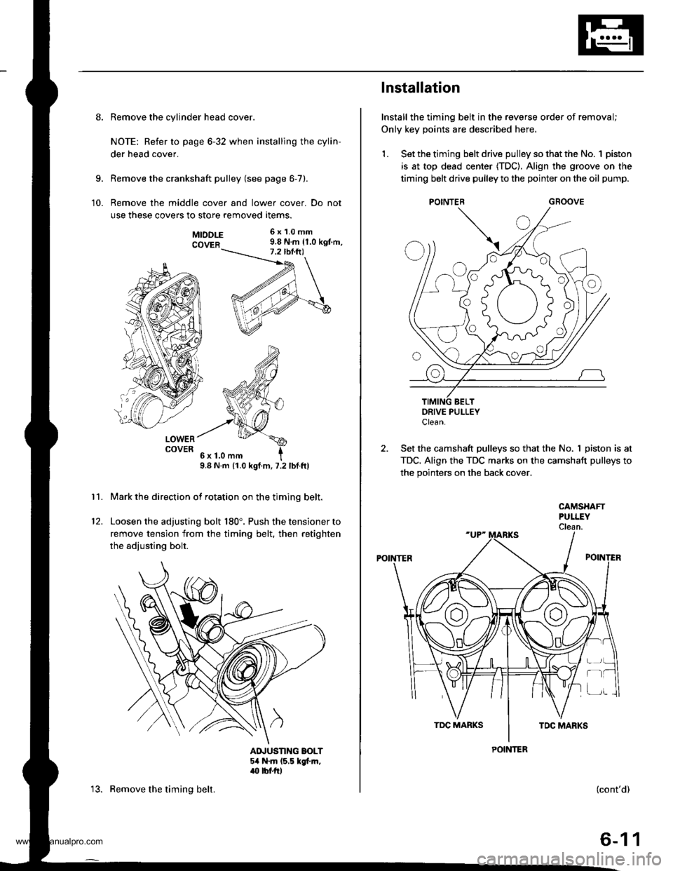
8. Remove the cylinder head cover.
NOTE: Refer to page 6-32 when installing the cylin-
der head cover.
Remove the crankshaft pulley (see page 6-7).
Remove the middle cover and lower cover. Do not
use these covers to store removed items.
9.
10.
11.
MTDDLE 6x1.0mm
COVER 9.8 N.m {1.0 kgt m,
LOWERCOVER
9.8 N.m (1.0 kgt.m, 7.2 lbf.ftl
Mark the direction of rotation on the timing belt.
Loosen the adjusting bolt 180'. Push the tensioner to
remove tension from the timing belt, then retighten
the adiusting bolt.
AINUSTING BOLT54 N.m (5,5 kgt m,.(} tbf.rrl
12.
13. Remove the timing belt.
Installation
Install the timing belt in the reverse order of removal;
Only key points are described here,
1. Set the timing belt drive pulley so that the No. 1 piston
is at top dead center (TDC). Align the groove on the
timing belt drive pulley to the pointer on the oil pump.
GROOVE
DRIVE PULLEYClean.
2. Set the camshaft pulleys so that the No. I piston is at
TDC. Align the TDC marks on the camshaft pulleys to
the pointers on the back cover.
POINTER
CAMSHAFTPULLEYClean.
POINTER
r-t
(cont'd)
6-11
www.emanualpro.com
Page 125 of 1395
Timing Belt
Installation (cont'd)
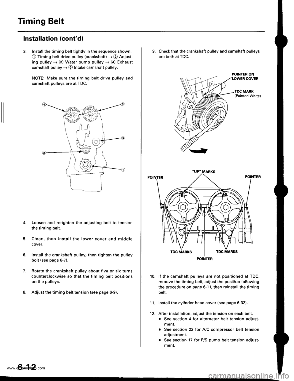
3. Install the timing belt tightly in the sequence shown.
O Timing belt drive pulley (crankshaft) J @ Adjust-
ing pulley =r @ Water pump pulley r @ Exhaust
camshaft pulley --) @ Intake camshaft pulley.
NOTE: Make sure the timing belt drive pulley and
camshaft pulleys are at TDC.
4. Loosen and retighten the adjusting bolt to tension
the timing belt.
5. Clean. then install the lower cover and middle
cover.
Install the crankshaft pulley, then tighten the pulley
bolt (see page 6-7).
Rotate the crankshaft pulley about five or six turns
counterclockwise so that the timing belt positions
on the pulleys.
Adjust the timing belt tension {see page 6-9).
1.
6-12
9. Check that the crankshaft pulley and camshaft pulleys
are both at TDC.
POINTER ON
lf the camshaft pulleys are not positioned at TDC,
remove the timing belt. adjust the position following
the procedure on page 6-11. then reinstall the timing
belt.
Installthe cylinder head cover (see page 6-32).
After installation, adjust the tension on each belt.
. See section 4 for alternator belt tension adjust-
menr.
. See section 22 for NC compressor belt tension
adjustment.
. See section 17 for P/S pump belt tension adjust-
ment.
10.
11.
12.
POINTER
www.emanualpro.com
Page 144 of 1395
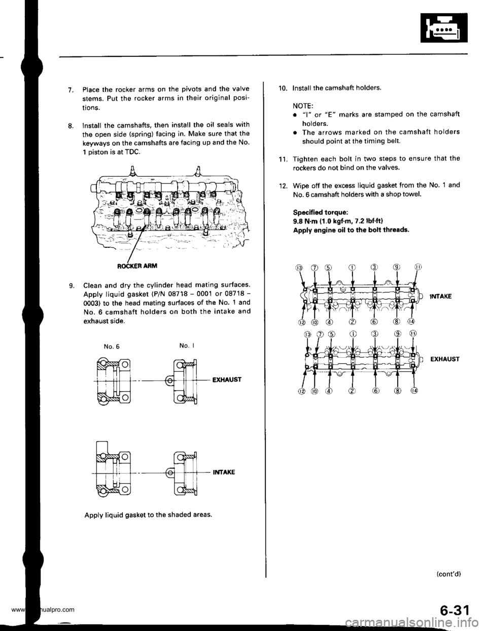
7.Place the rocker arms on the pivots and the valve
stems. Put the rocker arms in their original posi-
lrons.
lnstall the camshafts, then install the oil seals with
the open side (spring) facing in. Make sure that the
keyways on the camshafts are facing up and the No.
1 piston is at TDC.
Clean and dry the cylinder head mating surfaces.
Apply liquid gasket (P/N 08718 - 0001 or 08718 -
0OO3) to the head mating surfaces of the No. 1 and
No. 6 camshaft holders on both the intake and
exhaust side.
L
No. I
EXHAUST
II{TAKE
Apply liquid gasket to th€ shaded areas.
't't,
'10. lnstall the camshaft holders.
NOTE:
o "1" or "E' marks are stamped on the camshaft
holders.
. The arrows marked on the camshaft holders
should point at the timing belt.
Tighten each bolt in two steps to ensure that the
rockers do not bind on the valves.
Wipe off the excess liquid gasket from the No. 1 and
No. 6 camshaft holders with a shop towel,
Specified torque:
9.8 N.m (1.0 kgf.m, 7.2 lbf.ft)
Apply engine oil to the bolt ihreads.
I?,ITAKE
EXHAUST
(cont'd)
6-31
www.emanualpro.com
Page 145 of 1395

Cylinder Head
Installation (cont'dl
'13. Align the marks on the cylinder head plug to thecylinder head upper surface, then install the cylin
der head plug in the end of the cylinder head.
CYLINOER HEADPLUGReplace.
lnstallthe back cover.
To set the camshafts at TDC position for the No. lpiston, align the holes in the camshafts with theholes in the No. l camshaft holders and insert 5.0mm pin punches in the holes. Install the keys into
the camshaft grooves.
37 N m (3.8 *gl.m, 27 lbt.tr)
9.8 N.m (1.0 kgtm,7.2|hrftl
Push the camshaft pulleys onto the camshafts. thentighten the retaining bolts to the torque specified.
6-32
14.
KEYS
I x 1.25 mm
6x1.0mm
Install the timing belt (see page 6-1 1).
Adjust the valve clearance (see page 6-3).
Thoroughly clean the head cover gasket and thegroove.
lnstall the head cover gasket in the groove of thecylinder head cover. Seat the head cover gasket in
the recesses for the camshaft first, then work it into
the groove around the outside edges. Make sure thehead cover gasket is seated securely in the corners
of the recesses with no gap.
17.
'18.
19.
www.emanualpro.com
Page 204 of 1395

Fuel and Emissions
Special Tools ...................... 11-2
Component Locations
lndex ...................... ....,.... 11-3
Svstem Description
Vacuum Connections ...........,....,.,................. 1 1-9
Electrical Connections ................................... 1 1-15
System Connectors .,.,,.,............................,.,. 1 1-36
Troubleshooting
Troubleshooting Procedures,.,..................... 11-60
Engine Control Module/Powertrain ConttolModule Terminal Arrangement .............., 11-67
Diagnostic Trouble Code Chart .................... 1 t-75
How to Read Flowcharts .......,.....,.,............... I 1-79
PGM-Fl System
System Description .................,.,.,,,............... 1 1-80
Troubleshooting Flowcharts
Engine Control Module/PowertrainControl Module ........11-52
Manifold Absolute Pressure Sensor ............. 11-90
Intake Air Temperature Sensor .................... 1 1-95
Engine Coolant Temperature Sensor .,..,.,.... 1 1-99
Throttle Position Sensor ...........,.....,.,.,..,...... I 1'103
Primary Heated Orygen Sensor (Sensor 1) ... 11-110
Secondary Heated Oxygen Sensor{Sensor 2l .................. 1 1-117
Heated Oxygen Sensor Heater ..................... 11-121
Fuef Supply System ......11-124
Random Misfire ,....,.,..... 11-126
Mistire Detected in One Cylinder .....-........... 11-128
Knock Sensor ................ 11-130
CKP/TDC/CYP Sensor .................................... 1 1-131
Vehicle Speed Sensor ...............................,.... 1 1-135
Barometric Pressure Sensor .....,...,...,.,,........ 1 1-137
Electrical Load Detector ...,.,.......................... 1 1-138
CKF Sensor ................,.,, '11-112
ECM/PCM lnternaf Circuit ............................. 11'117
HO2S Replacement .,.,.,. 11-148
ldle Control System
System Description ............ 11-149
Troubleshooting Flowcharts
ldle Control System ...... 11-150
fdle Air Control Valve ......................,............. 11-152
Air Conditioning Signal ................................. I 1-155
Alternator FR Signal ...................................... 1 1-159
Starter Switch Si9na1 .................................... t l-161
Power Steering Pressure Switch Signal ...... 11-162
Brake Switch Si9na1 ...................................... 11-166
Fast ldle Thermo Valve .,.,.............................,.,.,. 11-168
ldle speed setting .............. 11-169
Fuel Supply System
Fuel Lines ............................ 11-171
Fuef Tube/Ouick-Conneci Fittings ..................... 11 -175
System Description ............ 11-178
Fuel Pressurg ...................... 11-178
Fuel Iniectors ................,..... 11-179
Fuel Pressure Re9u1ator .............................,.,...., f 1-181
Fuef Fifter ....,.,.,.,,,,.,............11-142
Fuel Pump ........................... 11-183
Fuel Gauge .......................... 11-184
Fuel Gauge Sending Unit ................................... I 1-185
Low Fuel Indicator System ...........,.,..,............... 1 1-185
PGM-FI Main Relay ............. 11-187
Fue|Tank................ ............. 11-191
Intake Air System
System Description ............ 11-193
Air Cleanel ,.,.,..................... 11-194
Throttle Cable ..................... 11-194
Throttle Body........ .............. 11-196
Emission Control System
System D$cription ...,....,.,. 11-199
Tailpipe Emission ............... 11-199
Three Way Catalytic Converter ..................,.,...,, 11-199
Positive Crankcase Ventilation System .,.,,,,.,.., 11-2O1
Evaporative Emission Controls .........,.,.,............ 11-203
www.emanualpro.com
Page 206 of 1395
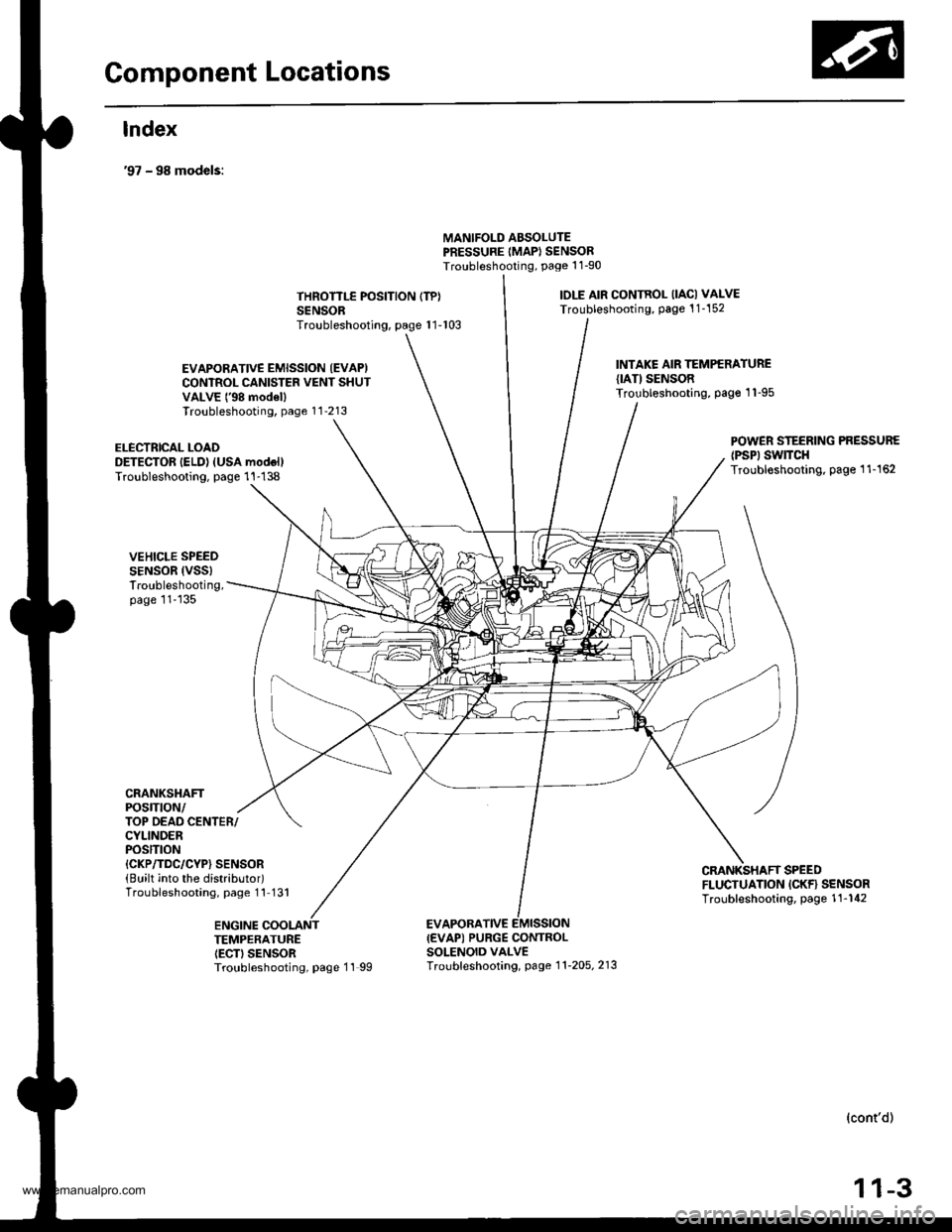
Component Locations
lndex
'97 - 98 models:
MANIFOLD ABSOLUTEPRESSURE IMAP} SENSORTroubleshooting, Page 1 1-90
THROTTLE POSITION (TP}
SENSORTroubleshooting, page 1 1-103
toLE AtR CONTROL llAcl VAI-VE
Troubleshooting, page 1 1-152
EVAPORATIVE EMISSION (EVAP)
CONTROL CANISTER VENT SHUTVALVE t'98 mod€llTroubleshooting, page 11'213
INTAKE AIR TEMPERATUREIIATI SENSORTroubleshooting. page 1 'l -95
ELECTRICAL LOADDETECTOR IELD) (USA modol)Troubleshooting, page 1 1-138
VEHICLE SPEEDSENSOR (VSS)
Troubleshooting,page 11'135
CRANKSHAFTPOSTTtON/
POWER STEERING PRESSURElPsPl swtrcHTroubloshooting, page 1 1-162
TOP OEAD CENTER/CYLINDERPOStTtON{CKP/TDC/CYP} SENSOR(Built into the distributor)Troubleshooting, page 1 l-131
CMNKSHAFT SPEEDFLUCTUATION ICKF} SENSORTroubleshooting. page 1'!-142
ENGINE COOLANTTEMPERATUREIECTI SENSORTroubleshooting, page 11 99
EVAPORATIVEI€VAP) PURGE CONTROLSOLENOID VALVETroubf eshooting, page 1 1'2o5, 213
(cont'd)
11-3
www.emanualpro.com
Page 207 of 1395
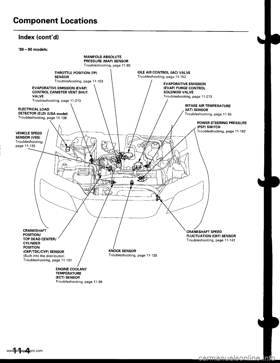
Component Locations
Index (cont'dl
39 - 00 models:
MANIFOLD ABSOLUTEPRESSURE IMAPISENSORTroubleshooting, page 1 1-90
THROTTLE POSITION {TP)SENSORTroubleshooting, page 1 1-103
IDLE AIR CONTROL OACI VALVETroubleshooting, page 1 1-152
EVAPOBATIVE EMISSION {EVAPICONTROL CANISTER VENT SHUTVALVETroubleshooting, page 1 1-213
EVAPORATIVE EMISSION(EVAPI PURGE CONTROI-SOLENOID VALVETroubleshootang, page 1 1-2'13
ELECTRICAL LOAOOETECTOR {ELD) IUSA modet)Troubleshooting, page I 1-138
INTAKE AIR TEMPERATURE(IAT) SENSORTroubleshooting, page 11 95
POWEB STEERING PRESSUREtPsPt swtTcHTroubleshooting, page 11 162VEHICLE SPEEDSENSOR IVSSITroubleshooting,page 11'135
CRANKSHAFTPOSTTTON/TOP OEAD CENTER/CYLINDERPOStTtON{CKP/TDC/CYP) SENSOR(Built into the distributor)Troubleshooting, page 11 131
CRANKSHAFT SPEEDFLUCTUATION ICKN SENSORTroubleshooting, page 1 1-142
SENSORTroubleshooting, page '11 130
ENGINE COOLANTTEMPERATURE{ECT)SENSORTroubleshooting, page 11 99
11-4
www.emanualpro.com
Page 218 of 1395
![HONDA CR-V 1997 RD1-RD3 / 1.G User Guide
Electrical Connections -97 Model
f_ --- --- -t _l-1r -lla^^^ tirrnl
(.J
no 3wrcx (-]lrLt -o.:\-tlDl"ii
\
HT:
v
l-I
tl
I-6,
I
4
^li lGPlf----;;ltl
tl
T
FUEL lltlEcToes
oa 9I3
aEt30F
TDC3ErcON
ct HONDA CR-V 1997 RD1-RD3 / 1.G User Guide
Electrical Connections -97 Model
f_ --- --- -t _l-1r -lla^^^ tirrnl
(.J
no 3wrcx (-]lrLt -o.:\-tlDl"ii
\
HT:
v
l-I
tl
I-6,
I
4
^li lGPlf----;;ltl
tl
T
FUEL lltlEcToes
oa 9I3
aEt30F
TDC3ErcON
ct](/img/13/5778/w960_5778-217.png)
Electrical Connections -'97 Model
f_ --- --- -t _l-1r -lla^^^ tirrnl
(.J
no 3wrcx (-]lrLt -'o.:\-'tlDl"ii
\
HT:
v
l-I
tl
I-6,
I
4
' ^li lGPlf----;;ltl
tl
T
FUEL ll'tlEcToes
oa 9I3
aEt30F
TDC3ErcON
ctPSErAOi
CKF3EN30F
TO EIIF-
*f
ctovEu
A' lGI
aztL@,
Xo.2|NJ2 3
ca tDcP[{J3 A2
cra Tltcl
||tL
Gt ct(iP?
er2 cxP{
cfl ct(Ftr
1
Dta ELtr
c|| v!]3TL T'
t ^cc ^r?to l/C CLUTCfl BELAYto i^Ol^toh F tl REI Y,@III'C|{AEi FA'I iEL Y
rtT
c. K.uirEuNxcoi||lEctoh
SERVICECl|ECK@ NEqroi
I ^ca 6
d__-lb
qr 3c3
ilaALTF CI'
rt: usAEII ATPI{PE
6uI)r^ l
t*frl
E
t'-
bI. ATPfi
B2a AtPtX
E' TPDI
Att lEFOgn3wltc
gi7 alP:l
I
I
ON
Ei. ATPID{ND tir
FUSES :(D BACK uP (RADro) (7.sr0.
@ "o^n ttot (tuo)'(D BATfERY (IOOA) *
o rcl (4oA)*
GAIXIEASSEIBLY
(DFt E/ flsA).@ No.13 FUEL PU P ('l5A)
O No. 2s METER (7.5A)(D NO. 'I5 ALTERNATOR SP SENSOB (7.5A) *
O No. 3i STABTER SIGNAL (7.5A)*: In lhc und?r.lrood tu$/rclay bor
(cont'd)
1 1-15
www.emanualpro.com
Page 268 of 1395
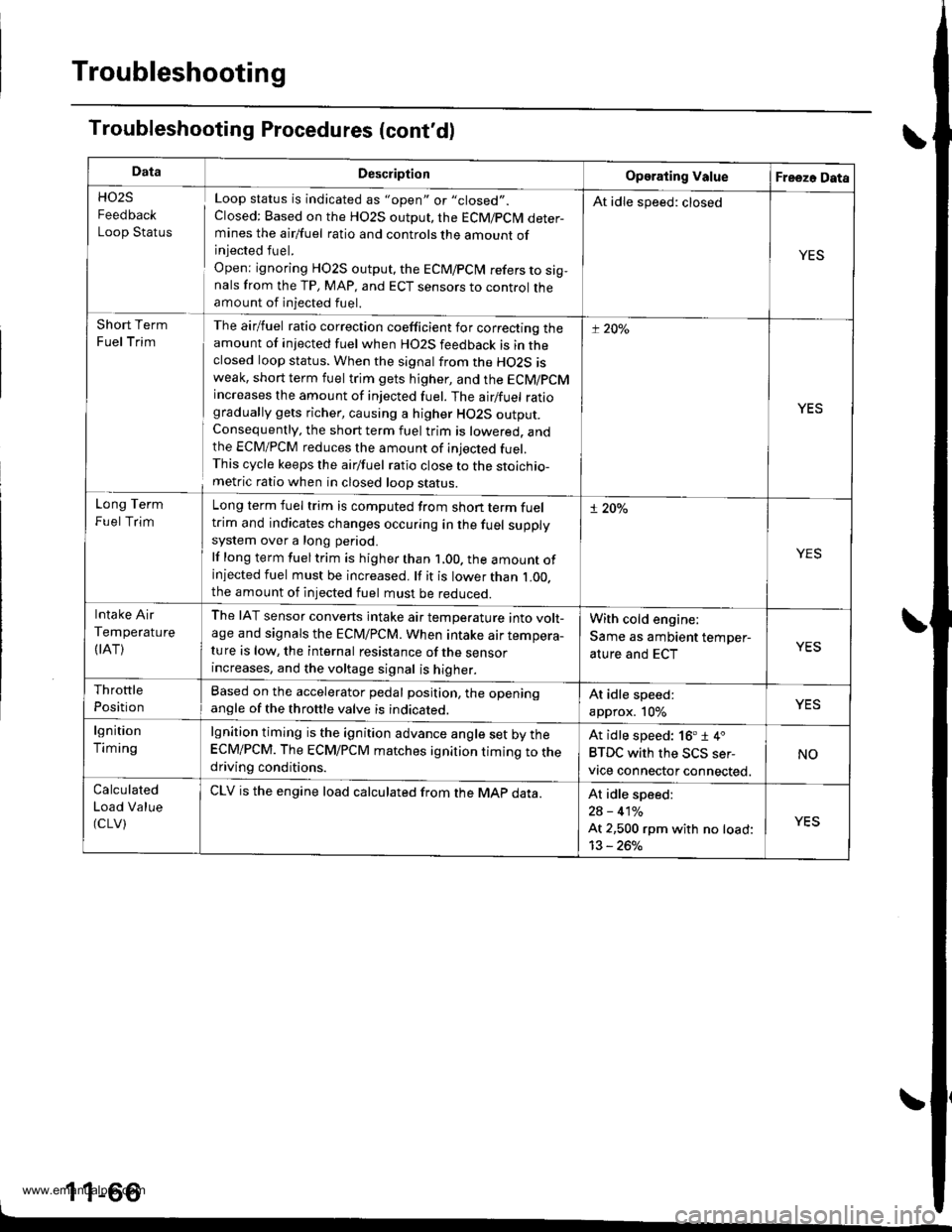
Troubleshooting
Troubleshooting Procedures (cont'd)
DataDescliptionOperating ValueFreezo Data
HO2S
Feedback
Loop Status
Loop status is indicated as "open" or "closed".
Closed: Based on the HO2S output, the ECM/pCM deter-mines the airlfuel ratio and controls the amount ofinjected fuel.
Open: ignoring HO2S output, the ECM/pCiM refers to sig,nals from the TP, MAP, and ECT sensors to control theamount of injected fuel.
At idle speed: closed
YES
Short Term
Fuel Trim
The airlfuel ratio correction coefficient for correcting theamount of injected fuel when HO2S feedback is in theclosed loop status. When the signal from the HO2S isweak, short term fuel trim gets higher, and the ECM/PCMincreases the amount of injected fuel. The airlfuel ratiogradually gets richer, causing a higher HO2S output.Consequently. the short term fuel trim is lowered. andthe ECM/PCM reduces the amount of injected fuel.This cycle keeps the airfuel ratio close to the stoichio-metric ratio when in closed looD status.
t:20y"
YES
Long Term
Fuel Trim
Long term fuel trim is computed from shon term fueltrim and indicates changes occuring in the fuel supplysystem over a long period.
lf long term fuel trim is higher than 1,00. the amount ofinjected fuel must be increased. lf it is lower than L00.the amount of injected fuel must be reduced.
! 20%
Intake Air
Temperature
(IAT)
The IAT sensor converts intake air temperature into volt-age and signals the ECrU/PCM. When intake air tempera-ture is low, the internal resistance of the sensorincreases, and the voltage signal is higher.
With cold engine:
Same as ambient temper-
ature and ECTYES
Throttle
Position
Based on the accelerator pedal position, the openingangle of the throttle valve is indicateo.At idle speed:
approx. 10%
lgnition
Timing
lgnition timing is the ignition advance angle set by theECM/PCM. The ECM/PCM matches ignition timing to thedriving conditions.
At idle speed: 16'1 4.
BTDC with the SCS ser-
vtce connector connected.
NO
Calculated
Load Value(cLV)
CLV is the engine load calculated from the MAp data.At idle speed:
2A - 410/o
At 2,500 rpm with no load:
13 - 260/o
YES
_
1 1_66
www.emanualpro.com
Page 271 of 1395
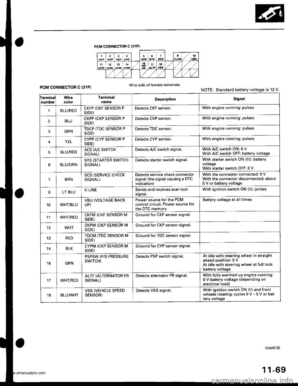
PCM CONNECTOR C (31PI
ferminalnumberWirecolorTerminalnameDoscriptionSignal
'tBLUiREDCKFP (CKF SENSOR PSIDE)Detects CKF sensor.With engine running: pulses
2BLUCKPP (CKP SENSOR PSIDE)Detects CKP sensor.With engine running: pulses
3GRNTDCP (TDC SENSOR PSIDE)Detects TDC sensor.With engine running: pulses
4YELCYPP (CYP SENSOR PSIDE)Detects cYP sensor.With engine running: pulses
5BLU,frEDACS (A/C SWTTCHSIGNAL)Detects A,/C switch signal.With AJC switch ON: 0 VWith A,/C switch OFF: battery voltage
BLU/ORNSTS (STARTER SWITCHSIGNAL)
Detects starter switch signal.With starter switch ON (lll): bafteryvoltageWith staner switch OFF: 0 V
7BRNSCS (SERVICE CHECKSIGNAL)
Detects service check connectorsignal (the signal causing a DTCindication)
With the connector connected: 0 V
With the connector disconnected: about
5 V or battery voltage
8LT BLUK-LINESends and receives scan toolsrgnal.With ignition switch ON (ll): pulses
10WHT/BLUVBUUP)
(VOLTAGE BACKPower source tor the PCMcontrol circuit. Power source for
the DTC memory
Battery voltage at all times
11WHT/REDCKFM (CKF SENSOR MSIDE)Ground for CKF sensor signal.
12WHTCKPM (CKP SENSOR I\4SIDE)Ground lor CKP sensor signal.
13REDTDCM (TDC SENSOR MSIDE}Ground for TDC sensor signal.
14BLKCYPM (CKP SENSOR MSIDE}Ground for CYP sensor signal.
16GRN
PSPSW (P/S PRESSUREswtTcH)Detects PSP switch signal.At idle with steering wheel in straightahead position:0 VAt idle with steering wheel at full lock:
battery voltage
17WHT/REDALTF (ALTERNATOR FRSIGNAL)
Detects alternator FR signal.With fully warmed up engine running:
0 V-battery voltage {depending onelectrical load)
18BLUA/VHTVSS (VEHICLE SPEEDSENSOR)Detects VSS signal.Wirh ignition switch ON (ll) and frontwheels rotating: cycles 0 V - 5 V or bat-tery voltage
Wire side of femaie terminalsPCM CONNECTOR C {31PINOTE: Standard battery voltage is 12 V.
(cont'd)
www.emanualpro.com