air con HONDA CR-V 1997 RD1-RD3 / 1.G User Guide
[x] Cancel search | Manufacturer: HONDA, Model Year: 1997, Model line: CR-V, Model: HONDA CR-V 1997 RD1-RD3 / 1.GPages: 1395, PDF Size: 35.62 MB
Page 74 of 1395
Gharging System
Troubleshooting
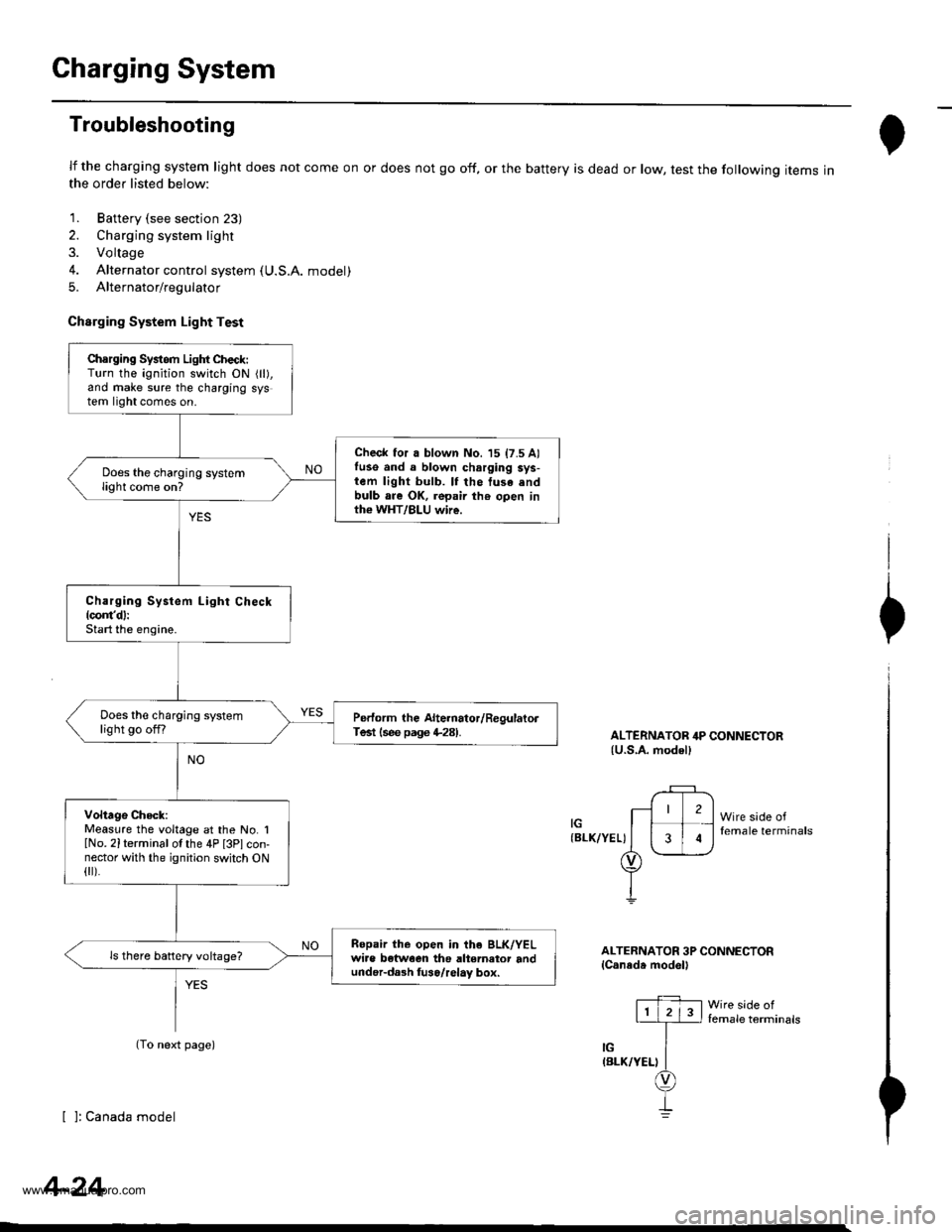
lf the charging system light does not come on or does not go off, or the battery is dead or low, test the following items inthe order listed below:
1. Battery (see section 23)
2. Charging system light
3. Voltage
4. Alternator control system (U.S.A. model)
5. Alternator/regulator
Charging System Light Test
ALTERNATOR 4P CONNECTOR{U.S,A. modell
(BLK/YEL)
2
3
Wire sade offemale terminals
I
I
I
ALTERNATOR 3P CONNECTORlCaneda model'
Iemale terminals
[ ]: Canada model
Chsrging Systom Light Check:Turn the ignition switch ON {ll),and make sure the charging system light comes on.
Check for a blown No. 15 17.5 Alfuse and a blown charging sys-tem light bulb. lf the tusa .ndbulb are OK, repair th€ open inth€ WHT/BLU wire.
Does the charging systemlight come on?
Charging System Light Check{com'd}:Start the engine.
Does the charging systemlight go offfPerform the Alte.nator/RegulatorTest lsee page +281.
Voltage Check:Measure the voltage at the No. IlNo. 2iterminal of the 4P [3Plcon-nector with the ignition switch ON{ ).
Ropair the open in the BLK/YELwiae betwoen the altemator andunder-da3h luso/relay box.
ls there battery voltage?
(To next page)
4-24
www.emanualpro.com
Page 75 of 1395
![HONDA CR-V 1997 RD1-RD3 / 1.G User Guide
in(From previous page)
Does the charging systemlight come on?
Ch6ck the L circuil:1. Turn the ignition switch OFF.2. Disconnect the 4P [3P] con-nector from the alternator.3. Turn the ignition switch HONDA CR-V 1997 RD1-RD3 / 1.G User Guide
in(From previous page)
Does the charging systemlight come on?
Ch6ck the L circuil:1. Turn the ignition switch OFF.2. Disconnect the 4P [3P] con-nector from the alternator.3. Turn the ignition switch](/img/13/5778/w960_5778-74.png)
in(From previous page)
Does the charging systemlight come on?
Ch6ck the L circuil:1. Turn the ignition switch OFF.2. Disconnect the 4P [3P] con-nector from the alternator.3. Turn the ignition switch ON (ll).
Repair the short to ground in theWHT/BLU wire.
[ ]: Canada model(cont'd)
4-25
www.emanualpro.com
Page 76 of 1395
Charging System
Troubleshooting (cont'dl
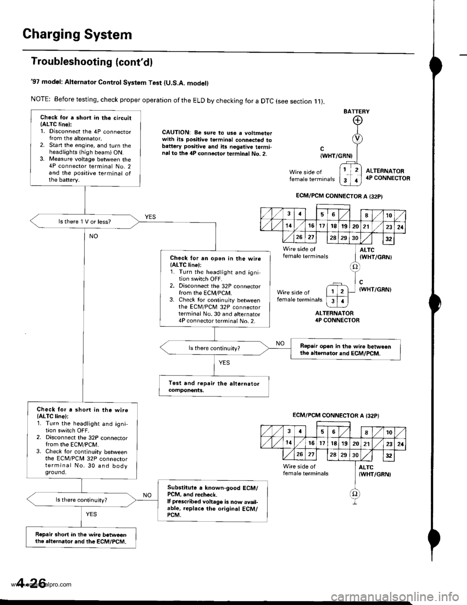
'97 modol: Alternator Control System Test {U.S.A. model)
NOTE: Before testing, check proper operation ofthe ELD by checking for a DTC (see section .11).
CAUTION: Be sure to use a voltmeterwith ils positive terminal connected tobattery positive and hs negative termi-nalto the 4P connector terminal No. 2.
BATTERY
Wire side offemale terminals
{WHT/GRNI
ALTERNATORirP CONNECTOR
ALTEFNATOR4P CONNECTOR
Chock for a short in the circuitIALTC line):1. Disconnect the 4P connectorfrom the alternator.2. Start the engine, and turn theheadlights thigh beami ON.3. Me8sure voltage between the4P connector terminal No. 2and the positive terminal ofthe battery.
lstherelVorless?
Check for an open in the wire(ALTC linel:1. Turn the headlight and igni-tion switch OFF.2. Disconnect the 32P connectorfrom the ECN4/PCM.3. Check tor continuity betweenthe EcM/PcM 32P connectorterminal No.30 and alternator4P connector terminal No. 2-
Repair open in the wi.e betwoenthe atternator and ECM/PCM.ls there continuity?
Check for a shorl in the wiroIALTC line):1. Turn the headlight and ign;,I|on swrtcn UFF2. Disconnect the 32P connectorfrom the EcM/PcM.3. Check tor continuity betweenthe ECM/PCN4 32P connectorterminal No. 30 and bodyground.
Subslitute a known-good ECM/PCM, and recheck.It prescribed voha96 b now avail-able, replace the original ECM/PCM.
ls there continuity?
R€prir short in the wire betweenthe altornator and the ECM/PCM.
ECM/PCM CONNECTOR A I32PI
,/1./1810
./ l./t4161718t9202121
26272A293032
Wire side of ] ALTCfemale terminals I tWHT/cRNl
tlWHT/GRN)
female terminals
I
1
ECM/PCM CONNECTOR A {32P}
,/ ,/46810
,/1,/1416l7t8'1920212321
272A2S30:t2
Wire side of I ALTCfemale terminals {WHT/GRNI
f)
4-26
www.emanualpro.com
Page 77 of 1395
R'oR
l
u
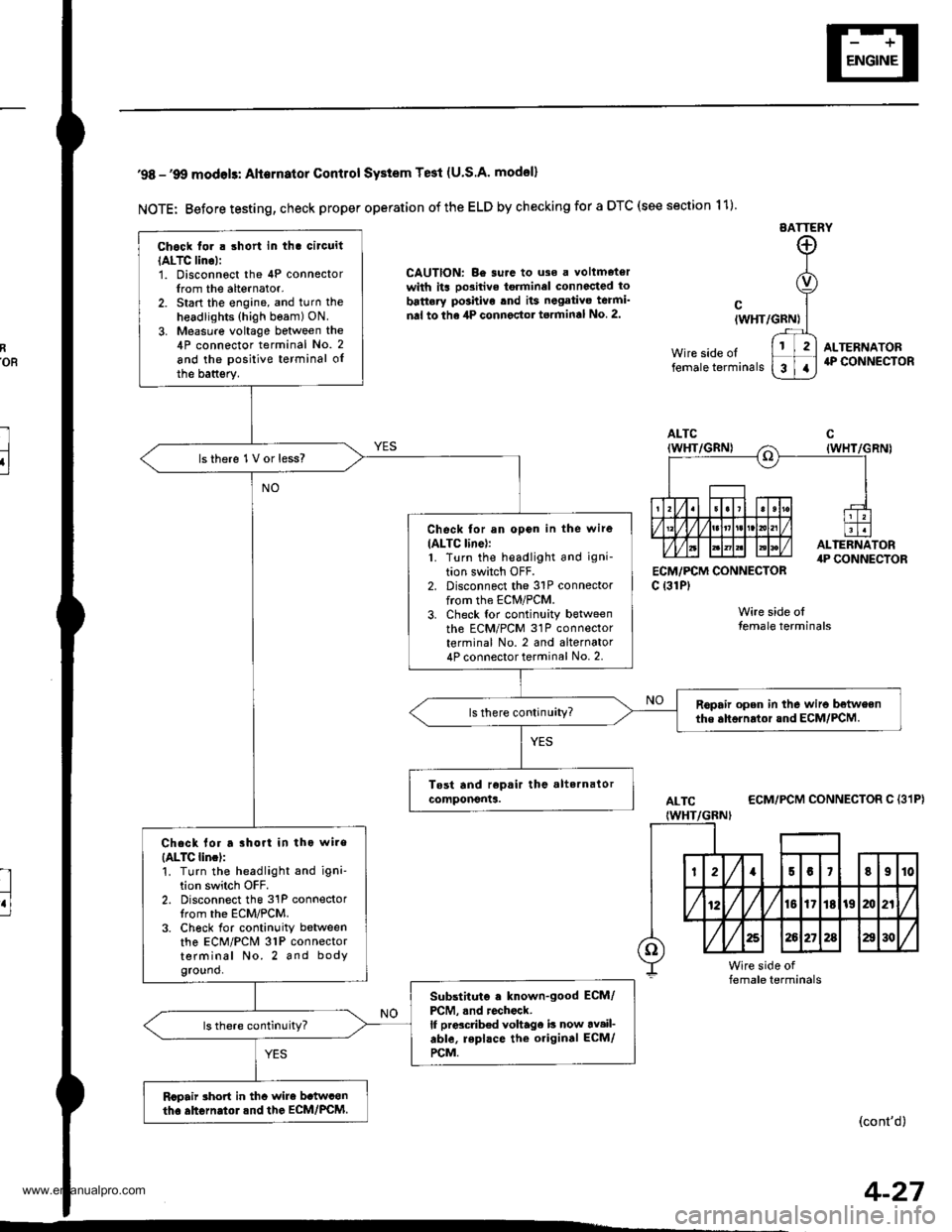
'98 -'9O modols: Alternator Contlol SYstem Te3t (U.S.A' model)
NOTE: Before testing, check proper operation of the ELD by checking for a DTC (see section 11)
EATTERY
CAUTION: Be surc to uso a voltmetorwith its oo3itive torminel connccted to
battery po3hivo tnd its negativo teami'
nal to the 4P connector torminal No 2.
ECM,/PCM CONNECTORc {31P)
Wire side olfemale terminals
cIWHT/GRN)
Wire side oltemale terminals
ALTERNATOR4P CONNECTOR
ALTC
IWHT/GBNI
ECM/PCM CONNECTOR C {31P}
(cont'd)
Chock tor . short in tha circuit
IALTC lino):1. Disconnoct the 4P connectorIrom the alternator.2. Start the engine, and turn the
headlights (high beam) ON.
3. Measure voltage between the4P connector terminal No. 2
and the positive terminal oIthe battsry.
lsthere 1V or less?
Check for an opon in the wire
IALTC line):1. Turn the headlight and igni-
tion switch OFF.2. Disconnect the 31P connectorfrom the ECM/PCM.3. Check tor continuity betweenth6 ECM/PCM 31P connectorterminal No. 2 and alternator4P connector terminal No. 2.
Ropair open in the wiro betweenthe ahornrtor and ECM/PCM.
Chack lor a rhort in tho wire
{ALTC lincl:'!. Turn the headlight and igni'tion switch OFF.2. Disconnect the 31P connectorIrom the ECM/PCM.3. Ch6ck for continuity betweenthe ECM/PCM 31P connectorterminal No. 2 and bodyground.
Substituto . known-good ECM/
PCM, .nd rochock.lf prdcdb€d voltage b now av.il-able, repl.ce the original ECM/
rcM.
Rcpair rhort in thc wire b.twconth. ahGrn.tol.nd the EcM/PcM.
4-27
www.emanualpro.com
Page 82 of 1395
Charging System
IRectifier Test
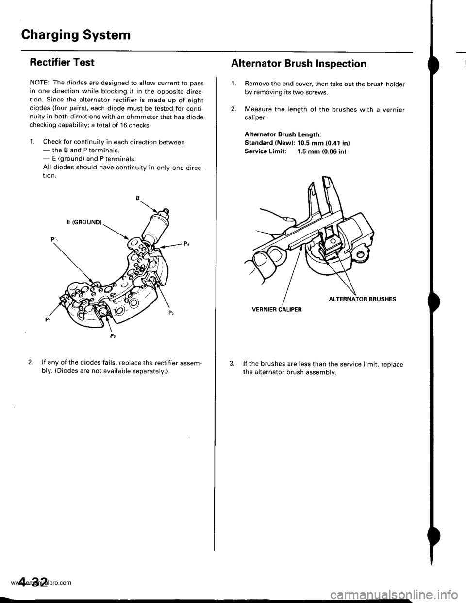
NOTE: The diodes are designed to allow current to pass
in one direction while blocking it in the opposite direc
tion. Since the alternator rectifier is made up of eight
diodes (four pairs), each diode must be tested for continuity in both directions with an ohmmeter that has diode
checking capability; a total of 16 checks.
'l. Check for continuity in each direction between- the B and P terminals.- E (ground) and P terminals.
All diodes should have continuity in only one direc-
tion.
2. lf any of the diodes fails, replace the rectifier assem-
bly. (Diodes are not available separatelv.)
4-32
1.
Alternator Brush Inspection
2.
Remove the end cover, then take out the brush holder
by removing its two screws.
Measure the length of the brushes with a vernier
calrper.
Alternator Brush Length:
Standard (Newl:10.5 mm 10.41 inl
Service Limit: 1.5 mm {0.06 in)
lf the brushes are less than the service limit, replace
the alternator brush assemblv.
VERNIER CALIPER
www.emanualpro.com
Page 83 of 1395
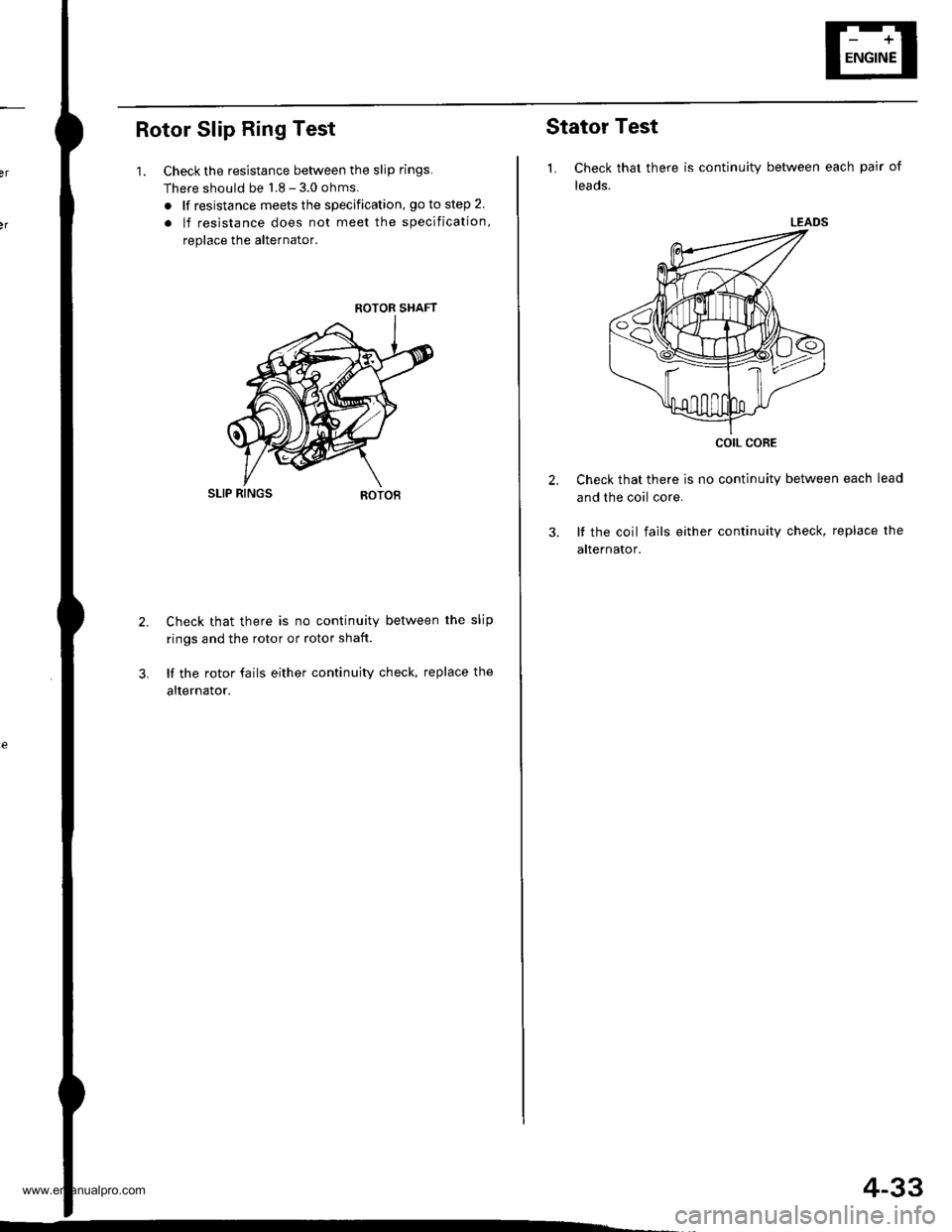
Rotor Slip Ring Test
1. Check the resistance between the slip rings.
There should be 1.8 - 3.0 ohms.
. lf resistance meets the specification, go to step 2
. lf resistance does not meet the specification,
replace the alternator.
SLIP RINGS
Check that there is no continuity between the slip
rings and the rotor or rotor shaft.
lf the rotor fails either continuity check, replace the
alternator.
ROTOR SHAFT
4-33
Stator Test
1. Check that there is continuity between each pair of
leads.
Check that there is no continuity between each lead
and the coil core.
It the coil fails either continuity check, replace the
alternator.
LEADS
corL coRE
www.emanualpro.com
Page 88 of 1395
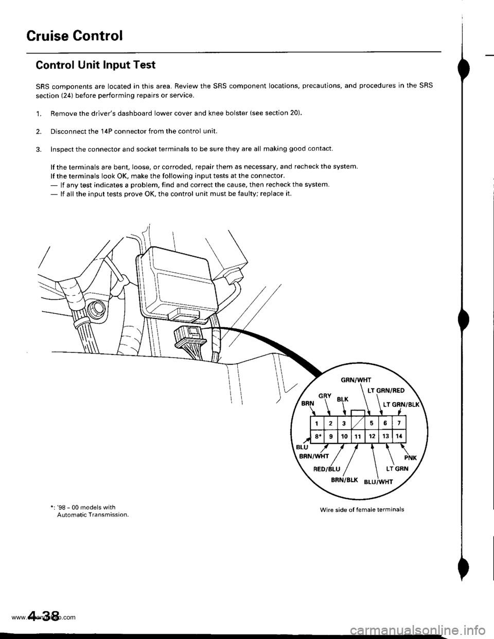
Cruise Control
Control Unit Input Test
SRS components are located in this area. Review the SRS component locations. precautions, and procedures in the SRS
section (241 before performing repairs or seryice.
'1. Remove the driver's dashboard lower cover and knee bolster {see section 20).
2. Disconnect the 'l4P connector from the control unit.
3. Inspect the connector and socket terminals to be sure they are all making good contact
lf the terminals are bent, loose, or corroded, repair them as necessary, and recheck the system.
lf the terminals look OK, make the following input tests at the connector.- lf any test indicates a problem. find and correct the cause, then recheck the system.
- lf all the input tests prove OK, the control unit must be faulty; replace it.
*: '98 - 00 models withAutomatic Transmission.Wire side ol female terminals
4-38
www.emanualpro.com
Page 90 of 1395
Cruise Control
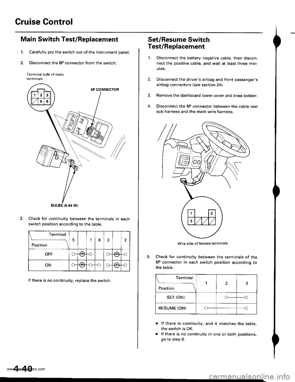
1.
Main Switch Test/Replacement
Carefully pry the switch out of the instrument panel.
Disconnect the 6P connector from the switch,
Terminal side of malerermtnats
6P CONNECTOR
/
Check for continuitv between the terminals in each
switch position according to the table.
lf there is no continuity, replace the switch.
BULES {0.84 Wt
Terminal
;;;
-_\56
OFFG-@oG(9,{)
ONG@-oo-@-o
4-40
Set/Resume Switch
Test/Replacement
1.Disconnect the baftery negative cable, then discon-
nect the positive cable, and wait at least three min-
utes.
Disconnect the driver's airbag and front passenger's
airbag connectors (see section 24).
Remove the dashboard lower cover and knee bolster.
Disconnect the 6P connector between the cable reel
sub harness and the main wire harness.
4.
Wire side of temale terminals
Check for continuity
6P connector in each
the table.
between the terminals of the
switch position according to
Terminal
;;;
--_l2
SET (ON)o--o
RESUME (ON)Cf-c
a
lf there is continuity. and it matches the table,
the switch is OK.
lf there is no continuity in one or both positions,
go to step 6.
www.emanualpro.com
Page 91 of 1395
n-
n-
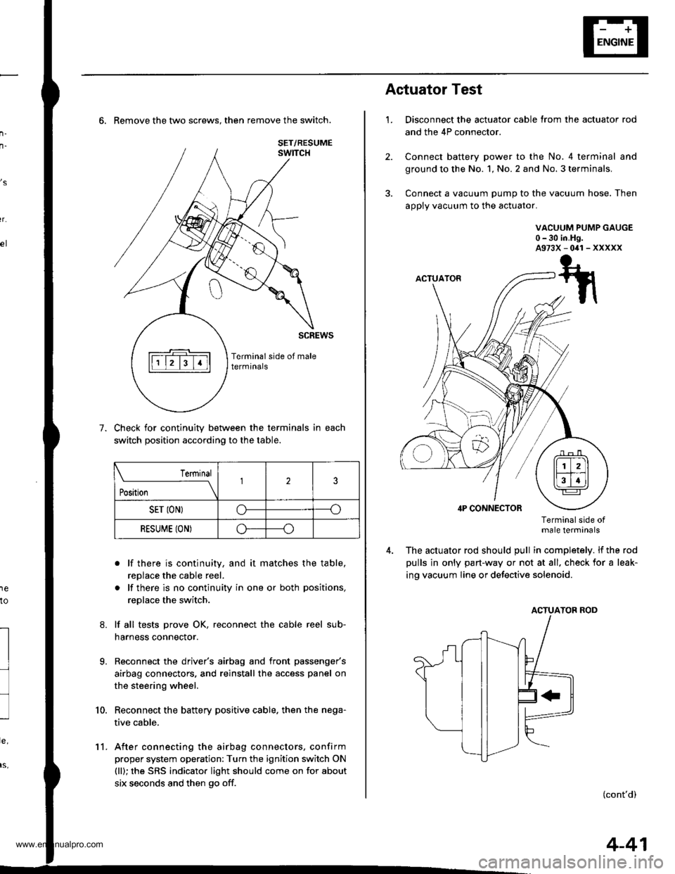
6. Remove the two screws. then remove the switch.
Check for continuity between the terminals in each
switch position according to the table.
. lf there is continuity, and it matches the table,
replace the cable reel.
. lf there is no continuity in one or both positions,
replace the switch.
lf all tests prove OK, reconnect the cable reel sub-
harness connector.
Reconnect the driver's airbag and front passenger's
airbag connectors, and reinstall the access panel on
the steering wheel.
Reconnect the battery positive cable. then the nega-
tive cable.
After connecting the airbag connectors, confirm
proper system operation: Turn the ignition switch ON
(ll); the SRS indicator light should come on for about
six seconds and then go off.
,s
r.
1e
to
7.
l
9.
10.
SET/RESUME
Terminal
t*,r*
-__\l23
SET ION)o----o
RESUME (ON)o----o
11.
4-41
1.
Actuator Test
Disconnect the actuator cable trom the actuator rod
and the 4P connector.
Connect battery power to the No. 4 terminal and
ground to the No. 1, No. 2 and No. 3 terminals,
Connect a vacuum pump to the vacuum hose. Then
apply vacuum to the actuator.
VACUUM PUMP GAUGE0-30 in.Hg.A973X-041-XXXXX
Terminalside otmale terminals
The actuator rod should pull in completely. lf the rod
pulls in only part-way or not at all, check for a leak-
ing vacuum Iine or defective solenoid.
ACTUATOB ROD
(cont'd)
www.emanualpro.com
Page 98 of 1395
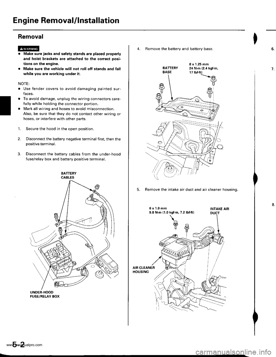
Engine RemovaUlnstallation
Removal
@a Make sure iacks and safety stands are placed properly
and hoist brackets are attached to the correct oosi-
tions on the engine.
. Make sure the vehicle will not roll oft stands and fall
while you are working under it.
NOTEI
. Use fender covers to avoid damaging painted sur-
faces.
o To avoid damage. unplug the wiring connectors care-
fully while holding the connector portion.
lvlark all wiring and hoses to avoid misconnection.
Also, be sure that they do not contact other wiring or
hoses, or interfere with other parts.
Secure the hood in the open position.
Disconnect the battery negative terminal first, then the
positive terminal.
Disconnect the battery cables from the under-hood
fuse/relay box and battery positive terminal.
1.
2.
4. Remove the batterv and batterv base.
BATTERYBASE
I x 1.25 mm24 N.m (2.4 kgf.m,17 tbnft)-t'.-e
F
FY
5. Remove the intake air duct and air cleaner housino.
INTAKE AIB
I
6.
7.
www.emanualpro.com