air con HONDA CR-V 1997 RD1-RD3 / 1.G Workshop Manual
[x] Cancel search | Manufacturer: HONDA, Model Year: 1997, Model line: CR-V, Model: HONDA CR-V 1997 RD1-RD3 / 1.GPages: 1395, PDF Size: 35.62 MB
Page 13 of 1395
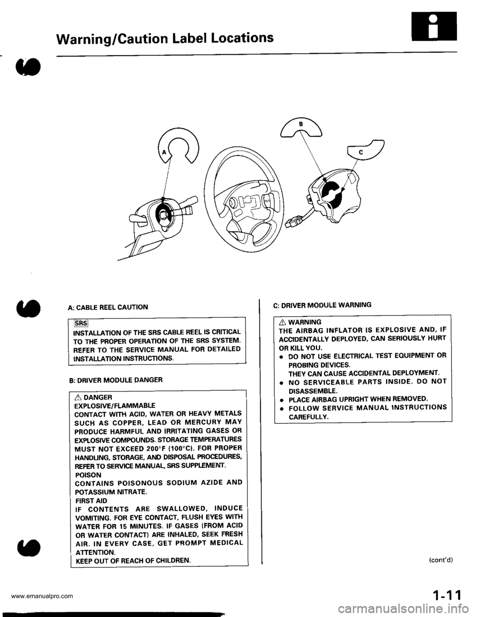
Warning/Caution Label Locations
C: DRIVER MODULE WARNING
A WARNING
THE AIREAG INFLATOR IS EXPLOSIVE AND, IF
ACCIDENTALLY DEPLOYED, CAN SERIOUSLY HURT
OR KILL YOU.
. DO NOT USE ELECTRICAL TEST EOUIPMENT OR
PROBING DEVICES.
THEY CAN CAUSE ACCIDENTAL DEPLOYMENT.
. NO SERVTCEABLE PARTS lNSlDE. DO NOT
DISASSEMBLE.
. PLACE AIRBAG UPRIGHT WHEN REMOVED
. FOLLOW SERVICE MANUAL INSTRUCTIONS
CAREFULLY.
A: CABLE REEL CAUTION
TNSTALLATION OF THE SRS CABLE REEL IS CRITICAL
TO THE PBOPER OPERATION OF THE SRS SYSTEM.
REFER TO THE SERVICE MANUAL FOR DETAILED
INSTALLATION INSTRUCTIONS.
(cont'd)
1-11
B: DRIVER MODULE DANGER
A DANGER
EXPLOSIVE/FLAMMABLE
CONTACT WITH ACID, WATER OR HEAVY METALS
SUCH AS COPPER, LEAD OR MERCURY MAY
PRODUCE HARMFUL AND IRRITATING GASES OR
EXPLOSIVE COMPOUNDS. STOMGE TEM PERATURES
MUST NOT EXCEED 2OO"F {1OO'C}. FOR PROPER
HANDUNG, STORAGE, AND DISPOSAL PROCEDURES.
REFER TO SERVICE MANUAI- SRS SUPPI.EMENT,
POTSON
CONTAINS POISONOUS SODIUM AZIDE AND
POTASSIUM NITRATE.
FIRST AID
tF CONTENTS ARE SWALLOWED, INDUCE
VOMITING. FOR EYE CONTACT, FLUSH EYES WITH
WATER FOR 15 MINUTES. IF GASES IFROM ACID
OR WATER CONTACTI ARE INHALED, SEEK FRESH
AIR. IN EVERY CASE, GET PROMPT MEDICAL
ATTENTION.
KEEP OUT OF REACH OF CHILDREN
www.emanualpro.com
Page 14 of 1395
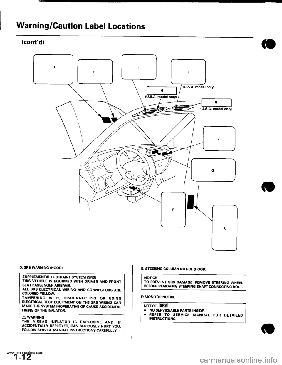
Warning/Caution Label Locations
(cont'dl
(U.S.A. modelonlyl
E: STEERING COLUMN NOTTCE tHOODI
NOTICETO PREVENT SRS DAMAGE, REMOVE STEERING WHEELBEFORE REMOVING STEERING SHAFT CONNECTING BOLT.
F: MONITOR NOTICE
NOTICE. NO SERVICEABLE PARTS tNStoE.. REFER TO SERVICE MANUAL FoR DETAILEDrNsrRucTtoNs.
{U.S.A. modol onlyl
o: SRS WARNING {HOOD}
SUPPLEMENTAL RESTRAINT SYSTEM {SRSITHIS VEHICLE IS EOUIPPED WITH DRIVER AND FRONTSEAT PASSENGER AIRBAGS,ALL SRS ELECTRICAL WIRING AND CONNECTORS ARECOLORED YELLOW.TAMPERING WITH, DISCONNECTING OR USINGELECTRICAL TEST EOUIPMENT ON THE SRS WIRING CANMAKE THE SYSTEM INOPERATIVE OR CAUSE ACCIDENTALFIRING OF THE INFLATOR.
A WARNINGTHE AIRBAG INFLATOR IS EXPLOSIVE AND. IFACCIDENTALLY DEPLOYED, CAN SEBIOUSLY HURT YOU.FOLLOW SERVICE MANUAL INSTRUCTIONS CAREFULLY.
1-12
www.emanualpro.com
Page 15 of 1395
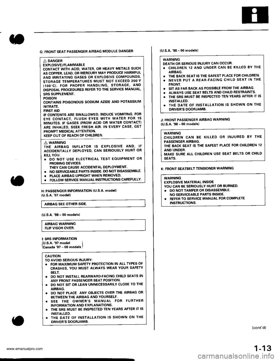
G: FRONT SEAT PASSENGER AIRBAG MODULE DANGEN
A DANGEREXPLOSIVE/FLAMMABLECONTACT WITH ACID, WATER. OR I{EAVY METALS SUCH
AS COPPER. T.EAD. OR MERCURY MAY PRODUCE HARMFUL
AND IRRITATING GASES OR EXPLOSIVE COMPOUNDS.
STORAGE TEMPERATURES MUST NOT EXCEED 2OO"F
IlOO'C). FOR PROPER HANDLING, STORAGE, AND
DISPOSAL PROCEDURES REFER TO THE SERVICE MANUAL,
SRS SUPPLEMENT.POTSONCONTAINS POTSONOUS SODIUM AZIDE ANO POTASSIUM
NITRATE.FIRST AIDIF CONTENTS ARE SWALLOWED, INDUCE VOMITING. FOR
EYE CONTACT, FLUSH EYES WITH WATER FOR 15
MINUTES. IF GASES (FROM ACID OR WATEN CONTACT)
ARE INHALEO. SEEK FRESH AIR. IN EVERY CASE, GET
PROMPT MEDICAL ATTENTION.KEEP OUT OF REACH OF CHILDREN.
A WARNINGTHE AIRBAG INFLATOR IS EXPLOSIVE AND, IF
ACCIDENTALLY DEPLOYED, CAN SERIOUSLY HURT OR
KILL YOU.. DO NOT USE ELECTRICAL TEST EOUIPMENT OR
PROBING DEVICES,THEY CAN CAUSE ACCIDENTAL DEPLOYMENT.. NO SERVICEABI-E PARTS lNSlDE. DO NOT DISASSEMBII.
. PLACE AIRBAG UPRIGHT WHEN REMOVEO.
. FOLLOW SERVIC€ MANUAL INSTRUCTIONS CAREFULLY
H: PASSENGER INFORMATION lU S.A. modell
{U.S.A.'97 model}
AIEBAG SEE OTHER SIDE,
{U.S.A.'98 - 00 modelsl
AIRBAG WARNINGFLIP VISOR OVER.
l: SRS INFORMATION
lU.s.A.'97 model ilcanada '97 - 00 mod€ls I
CAUTIONTO AVOID SERIOUS INJURY:. FOR MAXIMUM SAFEW PROTECTION lN ALL TYPES OF
CRASHES, YOU MUST ALWAYS WEAR YOUR SAFETY
8ELT.o OO NOT INSTALL REARWARD-FACING CHILO SEATS lN
ANY FRONT PASSENGER SEAT POSITION.. DO NOT SIT OR LEAN UNNECESSARILY CLOSE TO THE
AIRBAG.. DO NOT PLACE ANY OBJECTS OVER THE AIRBAG OR
BETWEEN THE AIRBAG AND YOURSELF.. SEE THE OWNER'S MANUAL FOR FURTHER
INFORMATION AND EXPLANATIONS. THE SRS MUST BE INSPECTED TEN YEARS AFTER lT lS
INSTALLED.. THE DATE OF INSTALLATION lS SHOWN ON THE
DRIVER'S DOORJAMB.
lU.S.A.'98 - 00 models)
WARNINGDEATH OR SERIOUS INJURY CAN OCCUR'
. CHILDREN 12 ANO UNDER CAN BE KILLED BY THE
AIRBAG.. THE BACK SEAT lS THE SAFEST PLACE FOR CHILDREN.
. NEVER PUT A REAR-FACING CHILD SEAT lN THE
FRONT.o SIT AS FAR BACK AS POSSIBLE FROM THE AIRBAG
. ALWAYS USE SEAT BELTS AND CHll-D RESTRAINTS.
. THE SRS MUST BE TNSPECTED TEN YEAnS AFTER lT lS
INSTALLED.. THE OATE OF INSTALLATION lS SHOWN ON THE
DRIVER'S DOORJAMB.
J: FRONT PASSENGER AIRBAG WARNING
lU.S.A.'98 - 00 models)
WARNINGCHILDREN CAN BE KILLED OR INJURED 8Y THE
PASSENGER AIRBAG.THE BACK SEAT IS THE SAFEST PLACE FOR CI{ILDREN 12
AND UNDER.MAKE SURE ALL CHILDREN USE SEAT BELTS OR CHILD
SEATS.
K: FRONT SEATBELT TENSIONER WARNING
WABNINGEXPLOSIVE MATERIAL INSIDEYOU CAN BE SERIOUSLY HURT OR BURNED,
. DO NOT TAMPER OR DISASSEMBLENO SERVICEABLE PARTS INSIDE.. REFER TO SERVICE MANUAL FOR COMPLETE
INSTRUCTIONS.
(cont'd)
1-13
www.emanualpro.com
Page 16 of 1395
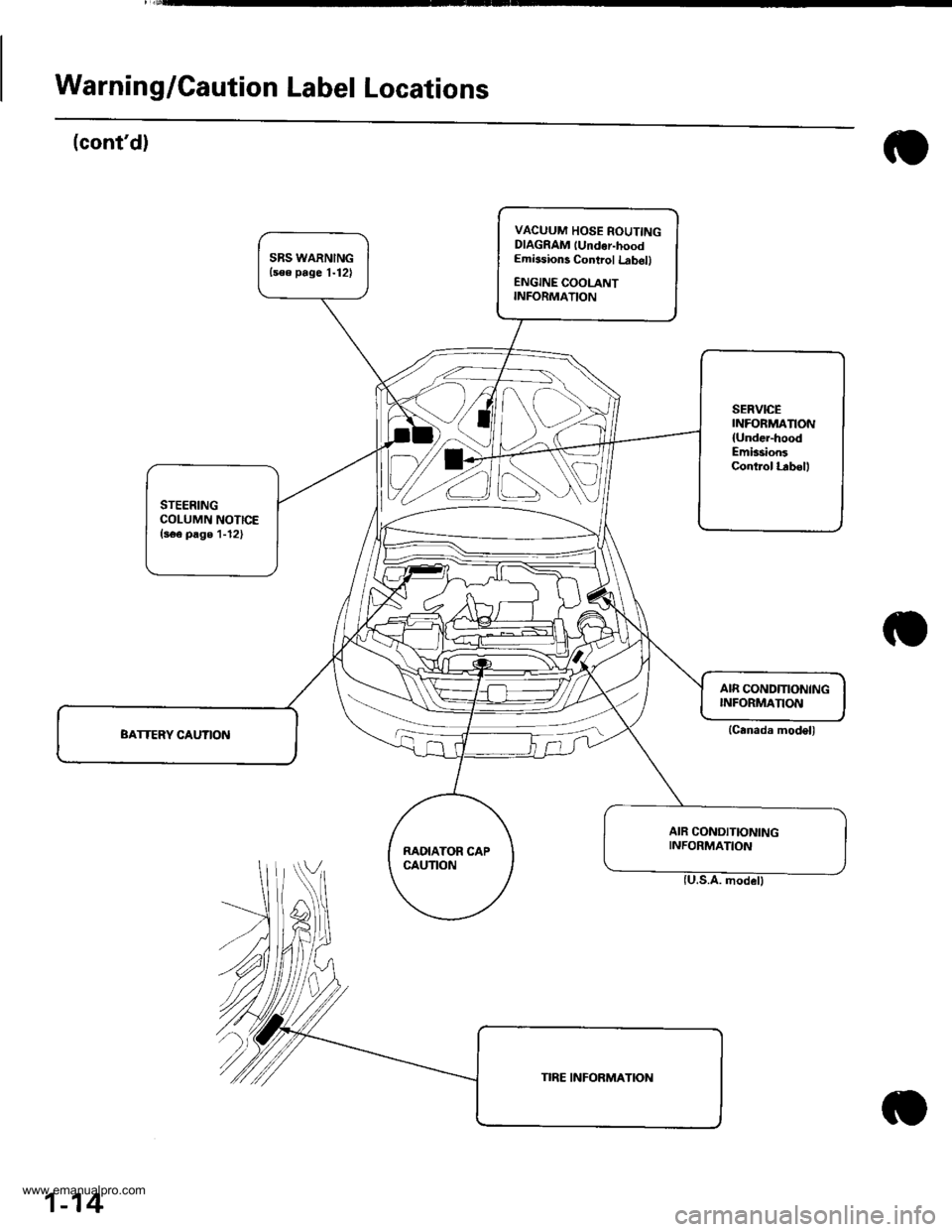
Warning/Caution Label Locations
(cont'd)
VACUUM HOSE ROUTINGDIAGRAM lUndor-hoodEmissions Control Lrb6ll
ENGINE COOLANTINFORMATION
SERVICEINFORMANON
{Under-hoodEmission3Control l.rbell
STEERINGCOLUMN NOTICE(s€e page 1-12)
RAOIATOR CAPCAUTION
AIR CONDITIONINGINFORMATION
(Canada model)
1-14
www.emanualpro.com
Page 20 of 1395
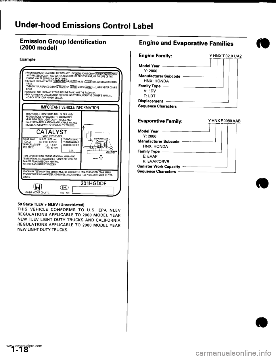
Under-hood Emissions Control Label
Emission Group ldentification
(2000 model)
Example:
DWFEN aDD r,tc 0R ChA\CtN! rlt cooraN. ust MsoLU- oN or fioNpA q-af6MrNp-ol
lfi ;!,."5:P!$t:1t9ffilf 1
vEn u u'r +-E coo|-d',r os-Fiiiiifi-'DREpf cE coolaNrAFTEBt3tlomistoR@MtLEs r@km),wH ctlEvrscoMEsT|E8EAFTER, BEprAcE EVEny ErdFst oB @ MttEs lmr,t, ffitcHEVER coMEsDCIIICX OF ADD COOLA I I'-FE AISIRVI TAI{I\. NOI THE MDIAIOR":3lliJ#fl "lj,9lx6L;T&Iji(0or|]\G s,5TEM 8r!D TrE owrEp s MA\u.r.
m
IMPORTANT VEHICLE INFORMATION
IHIS \/IHICLE CONFONMS TO U. S. EPA NLEVSEGULATIONS APPIJCq3LE TO 2OOO IVOOELYEAF NEW T!!V LIGHT DUTY TBUCKS ANDCALIFONNIA SEGULATIONS APPLICASLE TO 2OOOMOO€L YIAA NEW TLEV LIGHT.OUTY TFIJCKS.
CATALYST
vALvt LA5h tN:0,10r0.02 mm{C0t0l El:0.13!002 mhSPAn(PLUGGAP 1.0-11mmlDlE SPEEo 734150lpmO8O CENTFIED
?.0 t
TUNI UP CoNDIToNS: ENGINE AT NORMTTMPERAIURE ATLACCESSORIES fu BNITAN OFF TiANSMISS ON IN N€UTRALNO OTHER AD.ILJSTMENIS NEEDEO.
.l-L
|oAoEDr/MTESTNG oFTHsvtHrctE uLrst gt couolorooN,{raua.wxEtt onuspreosyNoiRoN zEo DvNAMoMETER. olrEiwsE. A NoN.LoAoEo rEsr pBocEounr uust sr pair
1
50 State TLEV + NLEV (Unrestricied,
THIS VEHICLE CONFORMS TO U.S. EPA NLEVREGULATIONS APPLICABLE TO 2OOO MODEL YEARNEW TLEV LIGHT DUTY TRUCKS AND CALIFORNIAREGULATIONS APPLICABLE TO 2OOO MODEL YEARNEW LIGHT DUTY TRUCKS.
1-18
Engine and Evaporative Families
Engine Family:Y HNX TO2.O UA2
Model Y€ar
Y: 2000
Manufaqturer Subcodo
HNX: HONDA
Family Type
V: LDV
T: LDT
Displacement
Saquenco Charasters
Evaporative Family:Y HNX EOOSOAAB
Modol Yea.
Y: 2000
Manufacturer Subcode
HNX: HONDA
Family Type
E: EVAP
R: EVAP/ORVR
Canister Work Capacity
Soquenca Charactet3
www.emanualpro.com
Page 36 of 1395
to
l
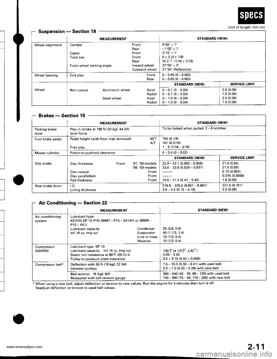
SuspensionSection 18
BrakesSec'tion 19
Air ConditioningSection 22
* When using a new belt, adjust deflection or tension to new values. Run the engine for 5 minutes then turn it off.
Readjust deflection or tension to used belt values.
o
Unit of length: mm {in)
MEASUREMENTSTANDARD {NEW)
WheelalignmentCamber FrontRearCaster FrontTotaltoe FrontnearFront wheel turning angle Inward wheelOutward wheel
0"00' 1 1'- 1"00' 1 1'2"10' ! 1"0J3(011/8)rN 2 ri (1/161 1/r6)37"00' ! 231'30'(Referencei
Wheel bearingEnd playFrontRear0 - 0.05 {0- 0.002}0 - 0.05 (0 0.002i
Rim runout Aluminum wheel AxialBadialSteelwheel AxialRadial
STANOARD (NEW)SERVICE LIMIT
0 - 0.7 (0 0.03)0,0.7 (0 - 0.03)0 1.0 (0 - 0.04)0 - 1.0 {0 - 0.04)
2.0 (0.08)'r.5 {0.06)2.0 {0.08)1.s (0.06)
MEASUREMENTSTANDARD INEWI
Parking brakeleverPlay in stroke at 196 N (20 kgf,44lbf)lever force
To be locked when Dulled: 2 - 6 notches
Foot brake pedalPedal height (with tloor mat removed)
Free playNT
155 (6 1/8)161 (6 5/16)1 5 (1/16 - 3/16)
Master cylinderPiston-to-pushrod clearance0 - 0.4 (0- 0.02)
Disc brakeDisc thickness Front '97, '98 models'99, '00 modelsDisc runoutDisc parallelismPad thickness
FrontFrontFront
STANDARD {NEW'SERVICE LIMIT
22.9 - 23.1 (0.902 - 0.909)23.6 23.8 (0.929 - 0.937)
10.5 - 11.5 (0.4'�t 0.45)
21.0 (0.83)
21.0 (0.83)
0.10 {0.004)0.015 (0.0006)
1.6 (0.06)
Rear brake drumLD.Lining thickness
2r9.9 220.0 (8.657 - 8.661)3.9 - 4.5 (0.15 - 0.18)221.O 8.70112.0 (0.08)
MEASUREMENTSTANDARD {NEWI
Air conditioningLubricant type:KEIHIN SP 10 (P/N 38897 - Pl3 - A01AH or 38899 -
Pl3 - A01)Lubricant capacity Condensermf {floz, lmp oz) EvaporatorLine or hoseReceiver
25 (5/6,0.9)
40 {1 1/3, 1.4)10 {1/3,0.4)10(.]/3,0.4)
Compressor(KEIHIN)Lubricant type: SP 10Lubricant capacity ml ({l 02, lmp oz}Stator coil resistance at 68'F (20"C) OPulley-to-pressuae plate clearance
130'3'{4 1fi'3o, 4.6;"}3.05 - 3.350.51 0.15 (0.02 1 0.006)
Compressor belt*Deflection with 98 N (10 kgl,22lblibetween pulleys7.5 - 10.5 {0.30 - 0.41) with used belt5.0 - 7.0 (0.20 - 0.28) with new belt
Belt tension N (kgf, lbf)Measured with belt tension gauge390 - 540 (40 55,88-120)withusedbelt740 - 880 {75 90, 170 - 200) with new belt
2-11
www.emanualpro.com
Page 38 of 1395

--
-
METRICITEMENGLISHNOTES
AIR CONDITIONINGCooling capacity3,520 Kcal/h j 14,000 BTU/h
Compressor Type/manutacturerNo. of cylinderCaPacityMax. speedLubricant capacityLubricant type
Scroll/KElHlN
85.7 mf/rev | 5.23 cu'in/rev10,000 rpm130mf 1 algIlozsP-10
Condenser TypeCorrugated fin
Evaporator TypeCorrugated fin
Blower TypeMotor inputSpeed controlMax. capacity
Sirocco fan200 w 112 v4-Speeo440 m3/h 15,500 cu fvh
Temperature control
Compressor clutch TypePower consumptionDry, single plate, poly-V-belt drive40 W max./12 VAt 68'F (20 C)
Befrigerant TypeOuantity
HFC-134a 1R-134a)zoo o' g 24j an oz
STEERING SYSTEMTypeOverall ratioTurns, lock to lockSteering wheel diameter
Power assisted, rack and pinion
SUSPENSIONType Front
Bear
Shock absorber Front and Rear
Independent double wishbone, coil springwith stabilizerIndependent double wishbone, coil springwith stabilizerTelescopic, hydraulic nitrogen gas tilled
WHEEL ALIGNMENTCamber
CasterTotaltoe
FronthearFrontFrontRear0inln 1/16 in0mmln2mm
0'- r"00'2.10'�
BRAKE SYSTEMTvpe
Pad surface areaLining surface areaParking brake
Front
RearFrontRearTvpe
Power-assisted selt-ad,ustingventilated discPower assisted self-adiusting drum49 cm, x 2 7.6 sq-in x 273 cm, x2 11.3 sq-in x 2Mechanical actuating, rear two wheel brakes
Drum brake
TIRESize and pressureSee tire inlormation label.
ELECTRICALBafteryStarterAlternator
In under-dash fuse/relay boxIn under hood fuse/relay box
In underhood ABS fuse/relay boxHeadlightsFront turn signal lights
Front parking lightsFront side marker lightsRear side marker lightsRear turn signal lightsErake/parking lightsBack-up lightsCeiling lights {fronvrear)License plate lightSpotlightsHigh mount brake lightlgnition key lightAshtray lightGauge lightsIndicator lightslllLrmination and pilot IightsHeater illumination lights
12 V, 36 AH/s HR12V 1.0, 1.1 kW12V 100A
7.5 A, 10 A, 15 A, 20 A7.5 A, 10 A, 15 A, 20 A, 30 A, 40 A'100 A7.5 4,20 A. 40 A12V 60/55 W12 V- 21 W ('97 model),12 V - 27 W ('98-00 models)12V 5 W {'97 model),3 CP ('98 - 00 models)12V-8W12 V,3 CP12V-21W12 V 2115 W12V 21 CP (18 W)12V-8W12V-8W12V-5W12V -21W
12 V- 1.4 W12V 1.4 W12 V 1.4 W,3 W,3.4 W12V-0.84W, 1.12 W, 1.4 W,3 W, LED12 V - 0.84 W, 1.4 W, LED12 V,1.4 W
2-13
www.emanualpro.com
Page 41 of 1395

Lubrication Points
For the details of lubrication points and type of lubricants to be applied. refer to the illustrated index and various work pro-
cedures (such as Assembly/Reassembly, Replacement, Overhaul, Installation, etc.) contained in each section.
Recomm6nded Engine OilEngine oil viscosity for ambient temperature ranges
100'F
-30 -20 .10 0 10 20 30 40'c
r1: Always use Genuine Honda Manual Transmission Fluid {MTF). Using motor oil can cause stiffer shifting because it
does not contain the orooer additives.*2: Always use Genuine Honda Premium Formula Automatic Transmission Fluid (ATF). Using a non-Honda ATF can affect
shift qualitv.+3r Always use Genuine Honda DOT 3 Brake Fluid. Using a non-Honda brake fluid can cause corrosion and decrease the
life of the system.*4: Always use Genuine Honda Power Steering Fluid. Using any other type of power steering fluid or automatic transmis-
sion fluid can caused increased wear and poor steering in cold weather.
API SERVICE LABEL
/,.*-G\
/.'z-\e\t/6AE\ll-;-1 5w-30 /---l
w
API CERTIFICATION SEAL
ffi-20 0 20
NO.LUBRICATION POINTSLUBRICANT
EngineAPI Service Grade: Use SJ "Energy Conserving" grade oil. The oilcontainer may also display the API Certitication seal shownbelow. Make sure it says "For Gasoline Engines." SAE vjscosity:See chart below.
2
TransmissionManualGenuine Honda MTF*1
AutomaticGenuine Honda Premium Formula Automatic Transmission Fluid(ATF)*'
3Rear differentialGenuine Honda CVT Fluid
4Brake line (includes ABS line)Genuine Honda DOT 3 Brake Fluid*3
5Clutch LineBrake fluid DOT 3 or DOT 4*3
6Shift lever pivots (Manual transmission)Grease with molybdenum disultide
1Release fork (Manual transmission)LJrea Grease UM264 P/N 4'1211 - PYs - 305
IPower steering gearboxSteering grease P/N 08733 - B070E
Throttle cable end {Dashboard lower panel holelSilicone grease
10l112
14
Throttle cable end (Throttle link)Brake master cylinder pushrodPedal linkageBattery terminalsFuelfill lidClutch master cylinder pushrod
Multi purpose grease
1617181920
Hood hinges and hood lockTailgate hingesHatch glass hingesDoor hinges, upper and lowerDoor opening detent
Honda White Lithium Grease
21
22
Caliper Piston seal, Dust seal,Caliper pin, PistonShilt cable and select cable {Manual transmission)Silicone grease
23Brake line ioints (Front and rear wheelhouse)Rust preventives
24Power steering systemGenuine Honda Power Steering Fluid-.
25Air conditioning compressorCompressor oil: SP 10 lP/N 38897 - P13 - A0lAH or38899-P13-A01)For Refrigerant: HFC 134a (R,134a)
3-2
www.emanualpro.com
Page 55 of 1395

Starting System
Starter Test
NOTE: The air temperature must be between 59 and'100'F (15 and 38"C) before testing.
Recommended Procedure:
. Use a staner system tester.
. Connect and operate the equipment in accordance
with the manufacturer's instructions.
. Test and troubleshoot as described.
Alte.nate Procedure:
. Use the following equipment:- Ammeter, 0 - 400 A- Voltmeter, 0 - 20 V (accurate within 0.1 volt)
Tachometer,0 - 1,200 rpm
. Hook up a voltmeter and ammeter as shown.
NOTE: After this test, or any subsequent repair. reset
the ECM/PCM to clear any codes (see section 1 1).
Check the Starter Engagement:
'1. Remove the No. 44 (15 A) fuse from the under-hood
fuse/relay box.
2. Turn the ignition switch to START (lll) with the shift
lever in E or E position (A/T) or with the clutch
pedal depressed {M/T). The starter should crank the
eng ine.
. lf the starter does not crank the engine, go to
step 3.
. lf it cranks the engine erratically or too slowly, go
to "Check for Wear and Damage" on the next
page.
NEGATIVE TERMINAL
4.
5.
6.
7.
8.
Check the battery, battery positive cable, ground.
staner cut relay, and the wire connections for loose-
ness and corrosion. Test again.
lf the staner still does not crank the engine, go to
step 4.
Unplug the connector (BLK /VHT wire and solenoid
terminal) from the starter.
Connect a jumper wire from the baftery positive (+)
terminal to the solenoid terminal.
The starter should crank the engine.
. lf the starter still does not crank the engine,
remove it, and diagnose its internal problem.
. lf the starter cranks the engine, go to step 6.
Check the ignition switch (see section 23).
Check the starter cut relay {see section 23}.
Check the IVT gear position switch (A/T) or the clutch
interlock switch (M[).
Check for an open in the wire between the ignition
switch and starter.
(cont'd)
4-5
www.emanualpro.com
Page 66 of 1395

lgnition System
5.
lgnition Timing Inspection and Setting
2.
1.Check the idle speed, and adjust it if necessary (see
section 1 1).
Pull out the service check connector 2P (BRN and
BLK wires) from the connector holder located under
the dash on the front passenger side, then connect
the scs service connector (P/N 07PAz - 0010100) to
it.
Start the engine. Hold the engine at 3,000 rpm with
no load (A/T in N or E, Mff in neutral) until the
radiator fan comes on, then let it idle.
Connect the timing light to the No. I ignition wire,
then point the light toward the pointer on the timing
belt cover.
Check the ignition timing in no load conditions:
headlights, blower fan, rear window defogger, and
air conditioner are not operating.
lgnition Timing:
M/T: 16" 12" BTDC (RED) idling in neutral
AlTt'16" !2" BTDC (RED) idling in E or E
CRANKSHAFTPULLEY
4-16
6. lf necessary, adjust the ignition timing as follows.
Loosen the distributor mounting bolts, and turn the
distributor ignition (Dl) housing counterclockwise to
advance the timing or clockwise to retard the tim-
t no,
7.
8.
MOUNTING BOLTS24 N.m {2.4 kgf m, 17 lbtft}
Tighten the distributor mounting bolts, and recheck
the ignition timing.
Disconnect the SCS service connector from the ser-
vice check connector.
To RETARD
www.emanualpro.com