cushion HONDA CR-V 1997 RD1-RD3 / 1.G User Guide
[x] Cancel search | Manufacturer: HONDA, Model Year: 1997, Model line: CR-V, Model: HONDA CR-V 1997 RD1-RD3 / 1.GPages: 1395, PDF Size: 35.62 MB
Page 858 of 1395
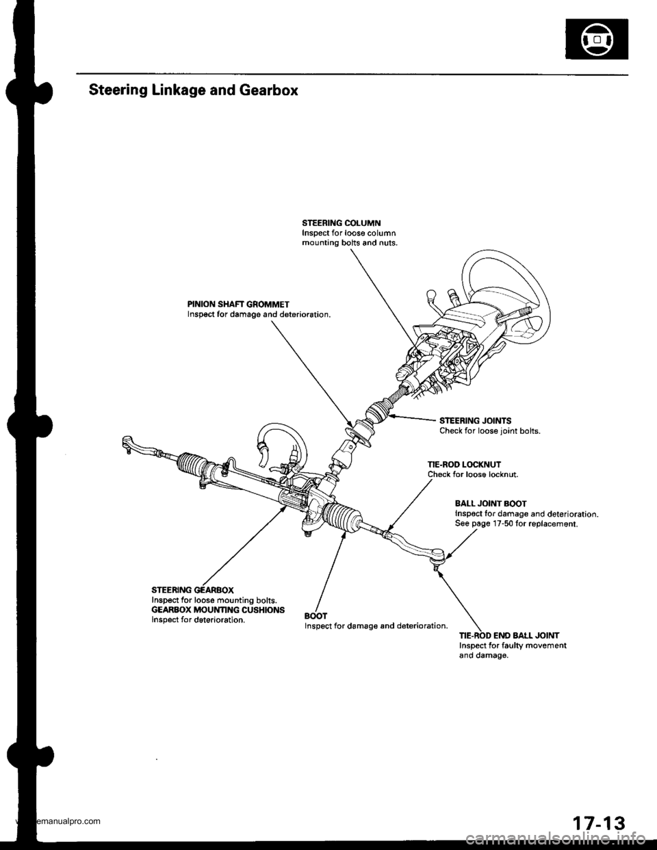
Steering Linkage and Gearbox
PINION SHAFT GROMMETInspoct for damage and deterioration.
STEERING JOINTSCheck for loose joint bolts.
NE-ROD LOCKNUTCheck Ior loose locknut.
Inspect for loose mounting bolts.GEARBOX MOUNTING CUSHIONSlnsp6ct for dgterioration.BOOTlnspect for damag€ and d€terioration.
BALL JONT AOOTInspoct lor damage and deterioration.S€e page 17-50 for replacemont.
END AAtL JOINTInspect for faulty movementano oamag€.
17-13
www.emanualpro.com
Page 896 of 1395
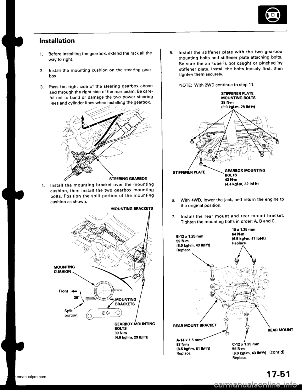
lnstallation
1. Before installing the gearbox, extend the rack all the
waY to right.
2. lnstall the mounting cushion on the steerlng gear-
box.
3. Pass the right side of the steering gearbox above
and through the right side of the rear beam. Be care-
ful not to bend or damage the two power steering
STEERING GEARBOX
Install the mounting bracket over the mounting
cushion. then install the two gearbox mounting
bolts. Position the split portion of the mounting
cushion as shown.
MOUNTING BBACKETS
GEARBOX MOUNTINGBOLTS39 N.m14.0 kgf.m, 29 lbf.ft)
:-
/
5. Install the stiffener plate with the two gearbox
mounting bolts and stiffener plate attaching bolts.
Be sure the air tube is not caught or pinched by
stiffener plate. Install the bolts loosely first. then
tighten them securely.
NOTE: With 2WD continue to step 11.
STIFFENER PLATEMOUNTING BOLTS38 N.m
1.
With 4WD, lower the iack, and return the engine to
the original Position.
lnstall the rear mount and rear mount bracket.
Tighten the mounting bolts in order: A, B and C.
8.12 x 1,25 mm
59 N.m(6.0 kgt.m. *l lb{'ftlReplace.
10 x 1.25 mm6,a N.m
16.5 kst.m, 47 lbl'ft)R€place.
)\^
o(]
17-51
www.emanualpro.com
Page 1004 of 1395
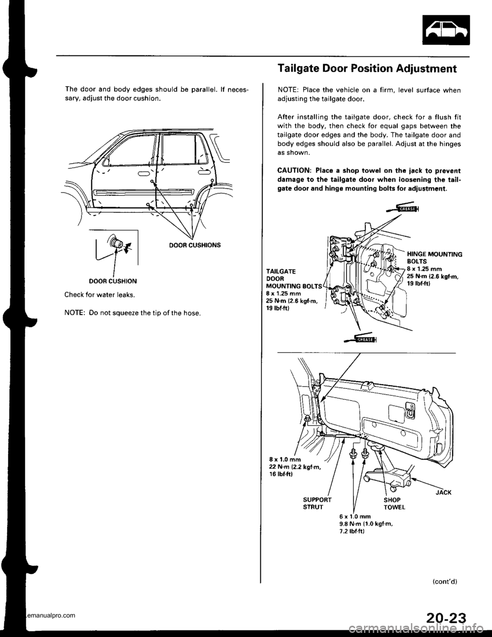
The door and body edges should be parallel. lf neces-
sary, adjust the door cushion.
ry.DOOR CUSHION
Check for water leaks.
NOTE: Do not squeeze the tip ofthe hose.
oooR cusHroNs
Tailgate Door Position Adjustment
NOTE: Place the vehicle on a firm, level surface when
adjusting the tailgate door.
After installing the tailgate door. check for a flush fit
with the body, then check for equal gaps between the
tailgate door edges and the body. The tailgate door and
body edges should also be parallel. Adjust at the hinges
as snown.
CAUTION: Place a shop towel on the iack lo prevent
damage to the tailgale door when loos€ning the tail-
gate door and hinge mounting bolts for adiustment.
TAILGATEDOORMOUNTING sOLTS8 x 1.25 mm25 N.m {2.6 kgf.m,19 tbf.ft)
HINGE MOUNYINGBOLTS8 x 1.25 mm25 N.m 12.6 kgt m,19 rbf.ftl
8x1.0mm22 N'rrl� 12.2 kgl.m,16 tbt.ftl
6xl.0mm9.8 N.m {1.0 kgt m,1.2 tbl.ltl
(cont'd)
20-23
www.emanualpro.com
Page 1039 of 1395
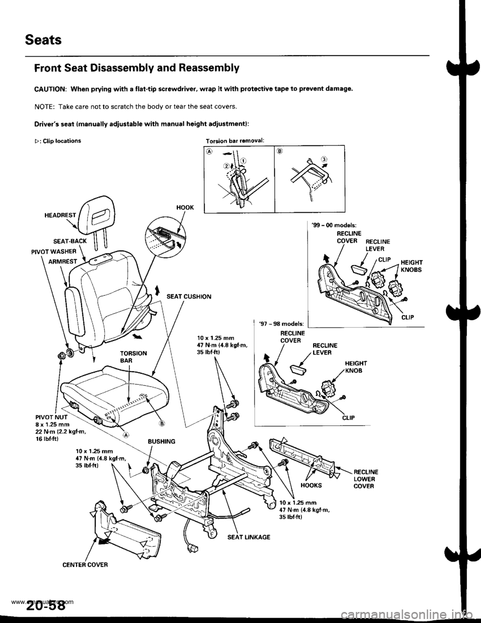
Seats
Front Seat Disassembly and Reassembly
CAUTION: When prying with a flat-tip screwdriver, wrap it with protsqtive tape to prevent damage.
NOTE: Take care not to scratch the bodv or tear the seat covers.
Driver's seat lmanually adiustable with manual height adiustmentl:
>: Clio locations Torsion bar removal:Torsion bar removal:
SEAT CUSHION
10 x 1.25 mm,17 N.m (,1.8 kgt m,35 tbt.ft)
PIVOT NUT8 x 1.25 mm22 N.n 12.2 kgl.m,16 rbI.ft)
10 x 1.25 mm47 N.m (4.8 kgf.m,35 tbtfr)
10 x 1 .25 mm47 N.m {,1.8 kgl.m.35 rbt.ft)
20-58
HOOK
HOOKS
www.emanualpro.com
Page 1040 of 1395
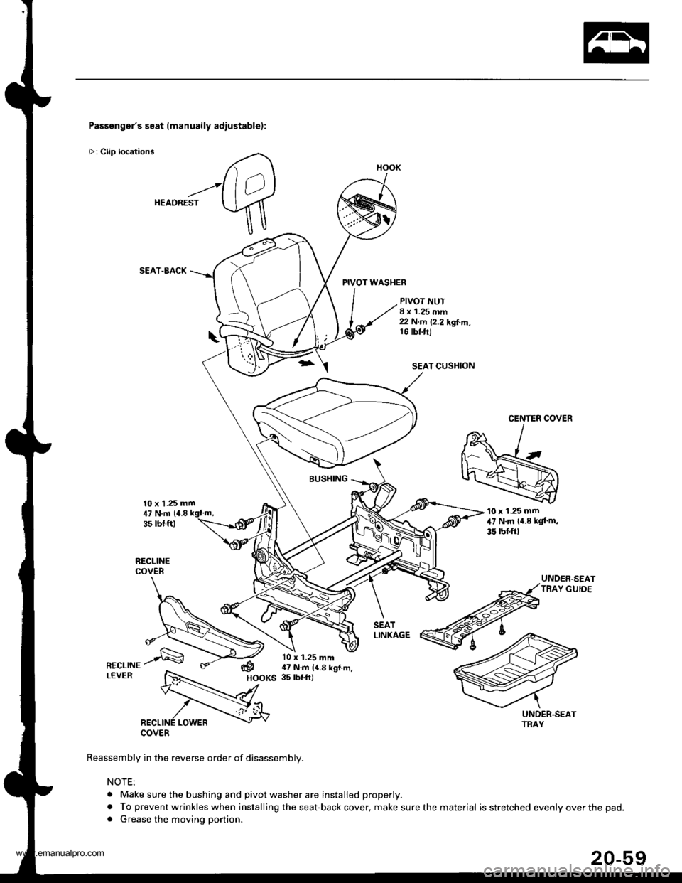
Passenger's seat (manually adiustablel:
>: Clip locations
HEADREST
SEAT.BACK
10 x 1.25 mm
PIVOT WASHER
PIVOT NUT8 x 1.25 mm22 N.m 12.2 kgl..n,16 tbt.ftl
SEAT CUSHION
CENTER COVER
BUSHING
COVER
Reassembly in the reverse order of disassembly.
NOTE:
. Make sure the bushing and pivot washer are installed properly.
. To prevent wrinkles when installing the seat-back cover, make sure the. Grease the moving portion.
'10 x 1.25 mm47 N.m {4.8 kgf m,
35 rbl.ft)
UNDER-SEATTRAY GUIDE
,U N.m 14.835 rbt.ft)
dHOOKS
10 x 1.25 mm17 N.m {4.8 kgl.m,35 tbf.ft)
HOOK
material is stretched evenly over the pad.
www.emanualpro.com
Page 1043 of 1395
Seats
Front Seat Cover Replacement (cont'dl
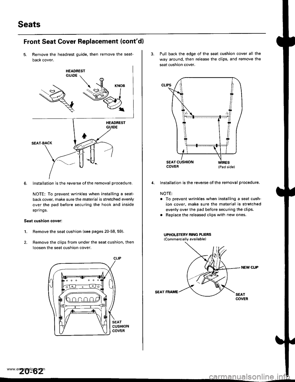
Remove the headrest guide, then remove the seat-
Dacx cover.
6. Installation is the reverse of the removal procedure.
NOTE: To prevent wrinkles when installing a seat-
back cover, make sure the material is stretched evenly
over the pad before securing the hook and inside
springs.
Seat cushion cover:
1.Remove the seat cushion (see pages 20-58, 59).
Remove the clips from under the seat cushion. then
loosen the seat cushion cover.
SEATCUSHIONCOVER
20-62
CLIP
3. Pull back the edge of the seat cushion cover all the
way around, then release the clips. and remove the
seat cushion cover.
COVER (pad side)
lnstallation is the reverse of the removal procedure.
NOTE:
. To prevent wrinkles when installing a seat cush-
ion cover. make sure the material is stretched
evenly over the pad before securing the clips.
. Replace the released clips with new ones.
UPHOLSTERY RING PLIERS
lCommercially available)
NEW CUP
SEAT FRAME
www.emanualpro.com
Page 1045 of 1395
Seats
Rear Seat Removal and Installation
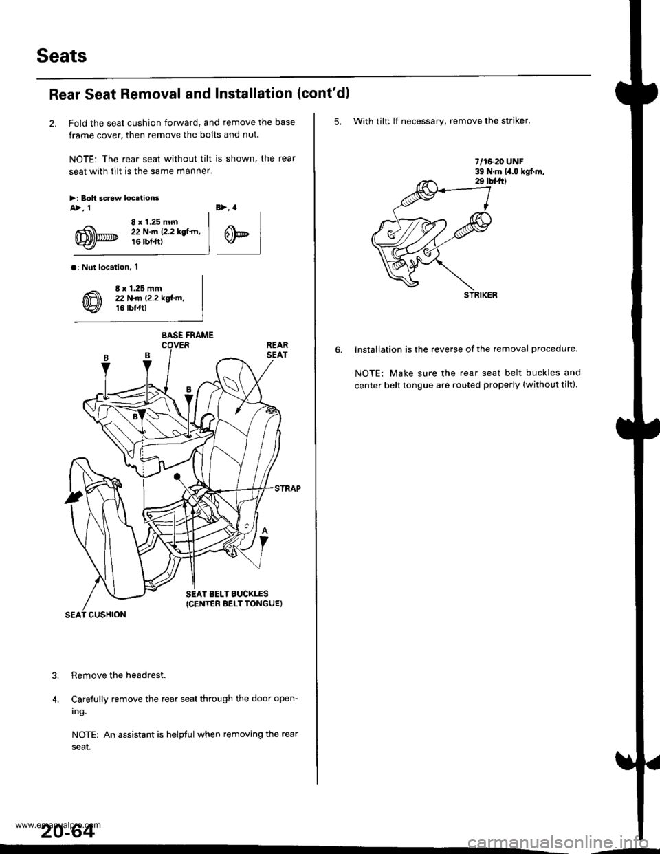
2. Fold the seat cushion forward, and remove the base
frame cover, then remove the bolts and nut.
NOTE: The rear seat without tilt is shown, the rear
seat with tilt is the same manner.
>i Boh screw locetionsA>, 1
8 x 1.25 mm22 N.m {2.2 kgf.rn,16 rbtft)
B>, 4
@t
a: Nut loc.iion, 'l
8 x 1.25 mm22 N
Carefully remove the rear seat through the door open-
ing.
NOTE: An assistant is helptul when removing the rear
seaI.
20-64
?
4.
BASE FRAME
SEAT BELT BUCKTES(CENTER BELT TONGUEI
SEAT CUSHION
(cont'dl
5. With tilt: lf necessary, remove the striker.
lnstallation is the reverse of the removal procedure.
NOTE: Make sure the rear seat belt buckles and
center belt tongue are routed properly (without tilt).
.-
www.emanualpro.com
Page 1046 of 1395
Rear Seat Disassembly and Reassembly
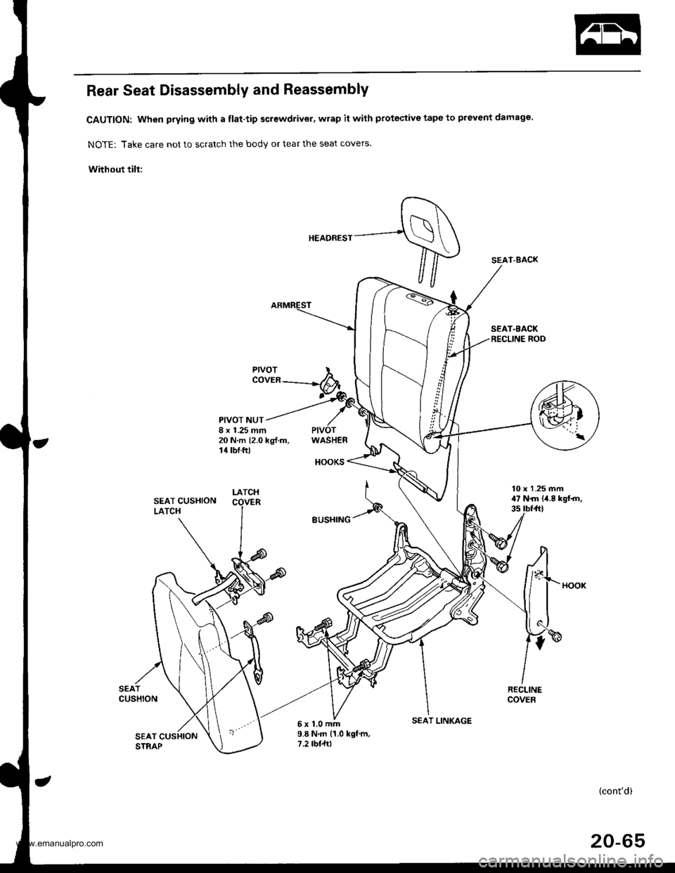
CAUTION: When prying with a flat-tip screwdriver, wrap it with protective tape to prevent damage.
NOTE: Take care not to scratch the body or tear the seat covers.
Without till:
SEAT.AACKRECLINE ROD
PIVOTCOVER
PIVOT NUT8 x 1.25 mm20 N.m 12.0 kg{.m.14 tbf.ftlWASHER
HOOKS
5x1.0mm9.8 N'm (1.0 kgf.m,7 .2 tbl.ltl
(cont'd)
20-65
SEAT-BACK
SEAT CUSHIONLATCH
SEATCUSHION
SEAT CUSHIONSTRAP
SEAT LINKAGE
www.emanualpro.com
Page 1047 of 1395
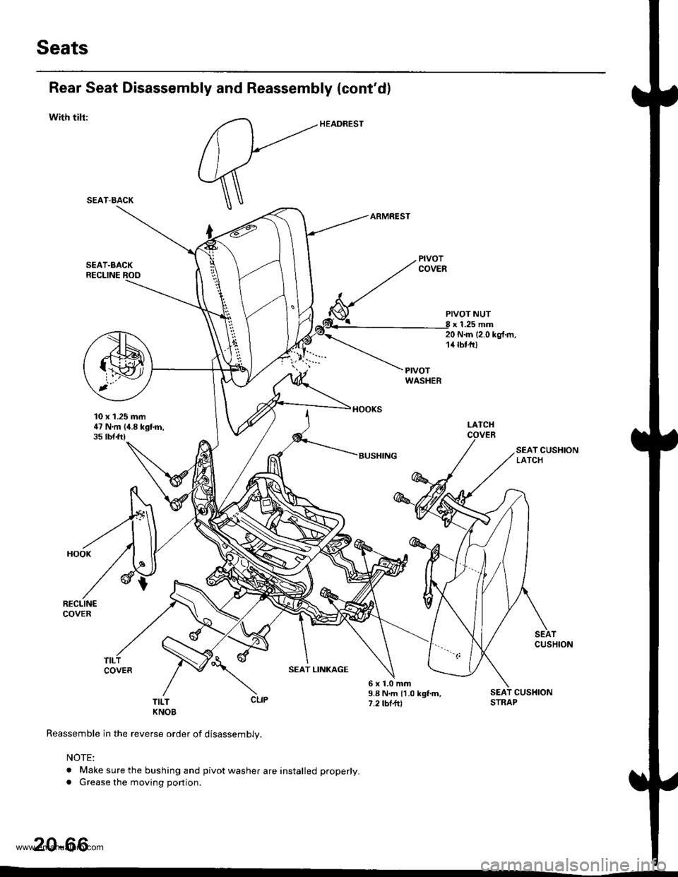
Seats
Rear Seat Disassembly and Reassembly (cont'd)
with tilr:
SEAT.BACKRECLINE ROO
10 x 1.25 mm47 N.m {4.8 kgfn,35 tbtft)
PIVOT NUTx 1.25 mm20 N{n (2.0 kgt.m,14 tbt-fr)
I-ATCHCOVER
SEAT CUSHIONLATCH
SEATCUSHION
SEAT LINKAGE
T;LT CLIP
KNOB
Reassemble in the reverse order of disassembly.
NOTE:
. Make sure the bushing and pivot washer are installed properly.. Grease the moving portion.
6x1.0mm9.8 N.m {1.0 kgf.m,7.2 tbf.ftl
SEAT CUSHIONSTRAP
20-66
SEAT-BACK
www.emanualpro.com
Page 1050 of 1395
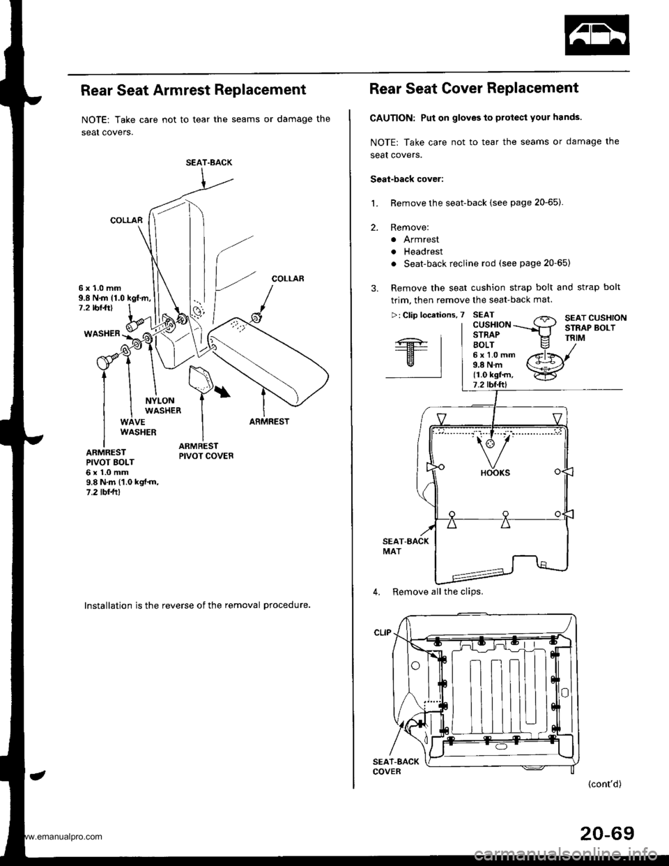
Rear Seat Armrest Replacement
NOTE: Take care not to tear the seams or damage the
seat covers.
COLLAR
COLLAR6x1.0mm9.8 N.m {1.0 kgf.m,7.2 rbr.ft)
WASHER
NYLONWASHER
VEARMRESTWASHER
ARMRESTPIVOT BOLT6x1.0mm9.8 N.m (1.0 kgt.m,7.2lbllll
lnstallation is the reverse of the removal procedure.
SEAT.BACK
Rear Seat Cover Replacement
CAUTION: Put on gloves to protect your hands.
NOTE: Take care not to tear the seams or damage the
seal covers.
Seal-back cover:
Remove the seat-back {see page 20-65).
Remove:
a Armrest
. Headrest
. Seat-back recline rod (see page 20-65)
Remove the seat cushion strap bolt and strap bolt
trim, then remove the seat-back mat.
L
2.
"'---.' t.-r" t-- i,': "" '
4. Remove all the clips.
(cont'd)
20-69
www.emanualpro.com