boot HONDA CR-V 1997 RD1-RD3 / 1.G Workshop Manual
[x] Cancel search | Manufacturer: HONDA, Model Year: 1997, Model line: CR-V, Model: HONDA CR-V 1997 RD1-RD3 / 1.GPages: 1395, PDF Size: 35.62 MB
Page 70 of 1395
lgnition System
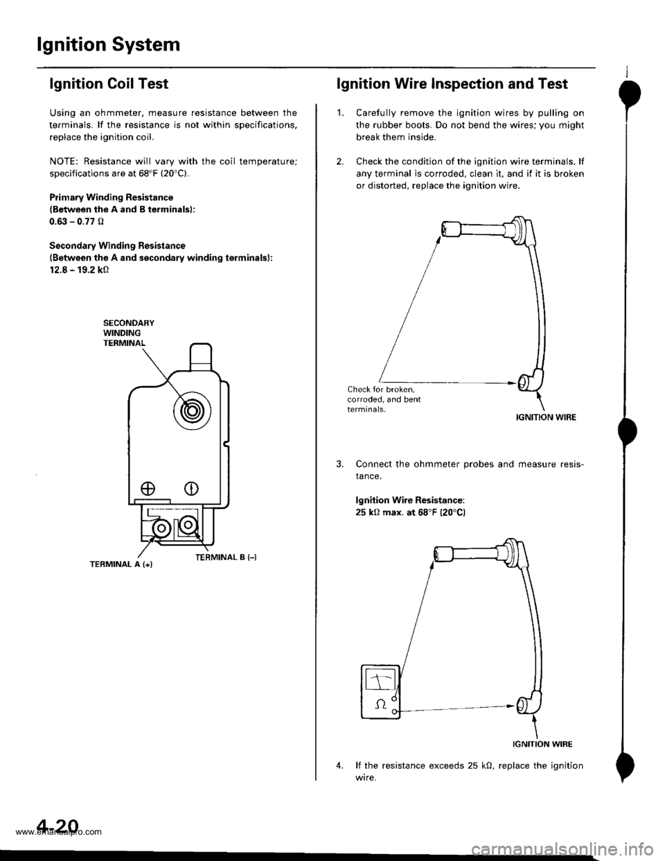
lgnition Coil Test
Using an ohmmeter, measure resistance between the
terminals. lf the resistance is not within sDecifications,
replace the ignition coil.
NOTE: Resistance will vary with the coil temperature;
specifications are at 68"F (20'C).
Plimary Winding Resistance
{Between the A and B terminals):
0.6it - 0.77 0
Secondary Winding Resistance
{Between the A and secondary winding terminals):
12.8 - 19.2 kO
TERMINAL A {+l
4-20
eo
lgnition Wire Inspection and Test
1.Carefully remove the ignition wires by pulling on
the rubber boots. Do not bend the wires; you might
break them inside.
Check the condition of the ignition wire terminals. lf
any terminal is corroded, clean it, and if it is broken
or distorted, replace the ignition wire.
IGNITION WIRE
Connect the ohmmeter probes and measure resis-
tance.
lgnition Wire Resistance:
25 kO max. at 68'F 120'Cl
IGNITION WIRE
4. lf the resistance exceeds 25 kO, replace the ignition
wire.
www.emanualpro.com
Page 92 of 1395
Cruise Gontrol
Actuator Test (cont'dl
5. With voltage and vacuum still applied, try to pull the
actuator rod out by hand. You should not be able topull it out. lf you can. it is defectrve.
8.
9.
7.
Disconnect ground from the No. 3 terminal. The actu-
ator rod should return. lf it does not return, but the
vent hose and filter are not plugged, the solenoid
valve assembly is defective.
Repeat steps 2 through 5. and disconnect ground
from the No. l terminal. The actuator rod should
return. lf it does not return, but the vent hose and
filter are not plugged, the solenoid valve assembly
is defective.
lf you replace the solenoid valve assembly, be sure
to use new O-rings on each solenoid.
Disconnect power and ground from the 4P connector.
Disconnect the vent hose from the actuator. Connect
a vacuum pump to the actuator vent hose port, and
apply vacuum. The actuator rod should pull in com-pletely. lf not, the vacuum valve is stuck open.
Replace the actuator,
4-42
I
't.
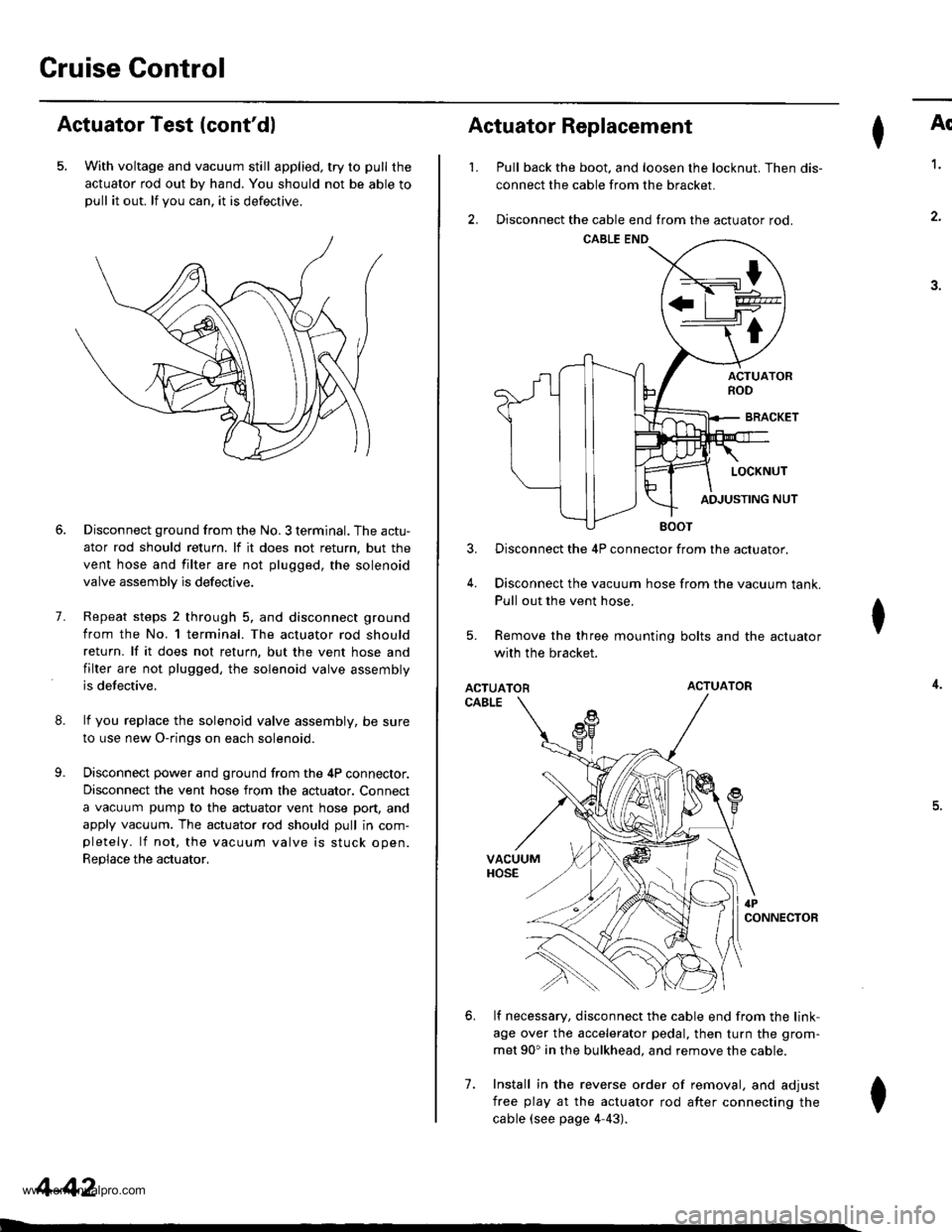
Actuator Replacement
3.
4.
7.
Ar
Pull back the boot. and loosen the locknut. Then dis-
connect the cable from the bracket.
Disconnect the cable end from the actuator rod.
1.
4.
.J.
Disconnect the 4P connector from the actuator.
Disconnect the vacuum hose from the vacuum tank.
Pull out the vent hose.
Remove the three mounting bolts and the actuator
with the bracket.
ACTUATORACTUATOR
CABLE
lf necessary, disconnect the cable end from the link-
age over the accelerator pedal, then turn the grom-
met 90' in the bulkhead. and remove the cable.
Install in the reverse order of removal, and adjust
free play at the actuator rod after connecting the
cable (see page 4-43).
I
6.
I
www.emanualpro.com
Page 433 of 1395
Slave Cylinder
RemovaUlnstallation
CAUTION:
. Do nol spill brake tluid on the vehicle; itmaydamage
the paint; if brake fluid do€s contast the paint, wash
it off immediately with water.. Plug the end of the clutch line with a shop towel toprevcnt brake tluid from coming out.
.6|l,Super High Temp Urea crease (p/N 08798 -
9002).
: Brake Assembly Lube or equivalent rubber
grease.
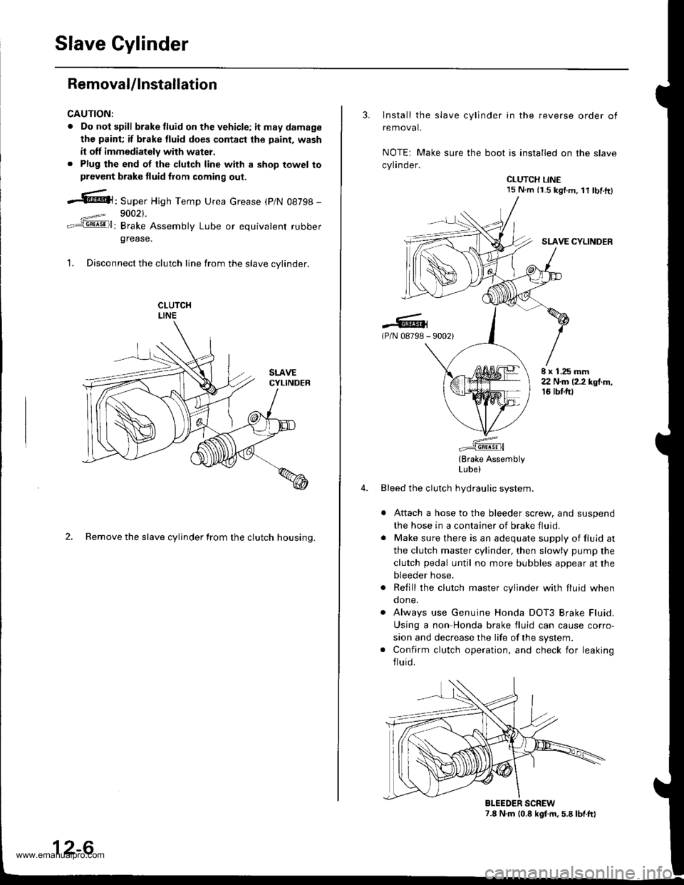
1. Disconnect the clutch line from the slave cvlinder.
2. Remove the slave cylinder from the clutch housing.
12-6
3. Install the slave cylinder in the reverse order ot
removal.
NOTEr Make sure the boot is installed on the slave
cylinder.
CLUTCH LINE15 N.m (i.S kgf.m, lt tbf.ftl
SLAVE CYLINDER
.-lG(P/N 08798 - 90021
E x 1.25 mm22 N.m (2.2 kgt.m,16 tbtft)
(Brake AssemblyLube)
Bleed the clutch hydraulic system.
Attach a hose to the bleeder screw, and suspend
the hose in a container of brake fluid.
Make sure there is an adequate supply of fluid at
the clutch master cylinder, then slowly pump the
clutch pedal until no more bubbles appear at the
bleeder hose.
Refill the clutch master cylinder with fluid whenqone.
Always use Genuine Honda DOT3 Brake Fluid.
Using a non Honda brake fluid can cause corro-
sion and decrease the life of the system.
Confirm clutch operation, and check for leaking
fluid.
7.8 N.m (0.8 kgf.m. 5.8 lbt.ft)BLEEDER SCREW
www.emanualpro.com
Page 438 of 1395
Release Bearing
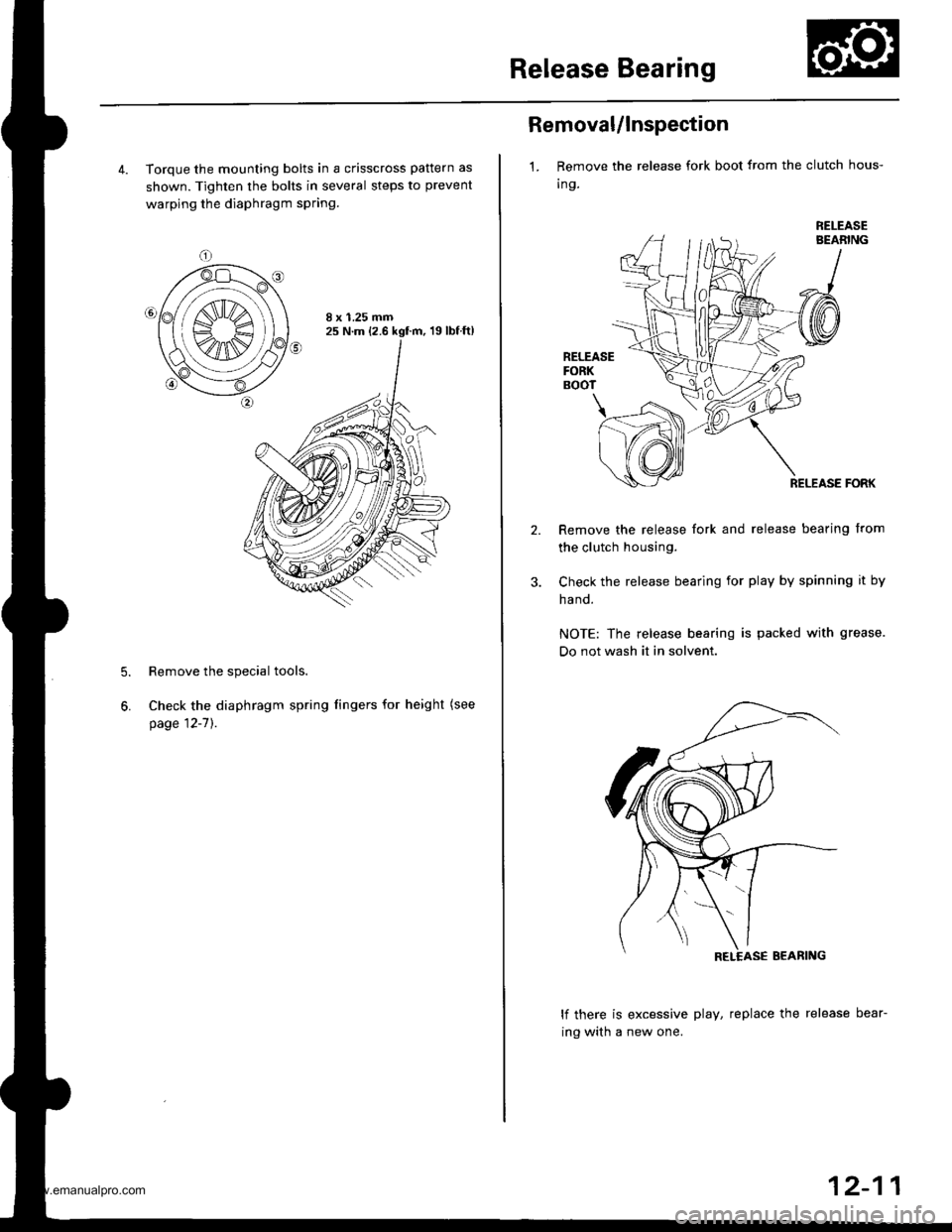
4. Torque the mounting bolts in a crisscross pattern as
shown. Tighten the bolts in several steps to prevent
warping the diaphragm spring.
8 x 1.25 mm25 N.m (2.6 kgf.m, 19lbfft)
Remove the special tools.
Check the diaphragm spring fingers for height (see
page 12-7]'.
5.
6.
Removal/lnspection
1. Remove the release fork boot from the clutch hous-
Ing.
RELEASEBEABING
RELEASEFORKBOOT
\
RELEASE FORK
Remove the release fork and release bearing from
the clutch housing.
Check the release bearing for play by spinning it by
ha nd.
NOTE: The release bearing is packed with grease.
Do not wash it in solvent.
lf there is excessive play, replace the release bear-
ing with a new one.
12-11
www.emanualpro.com
Page 439 of 1395
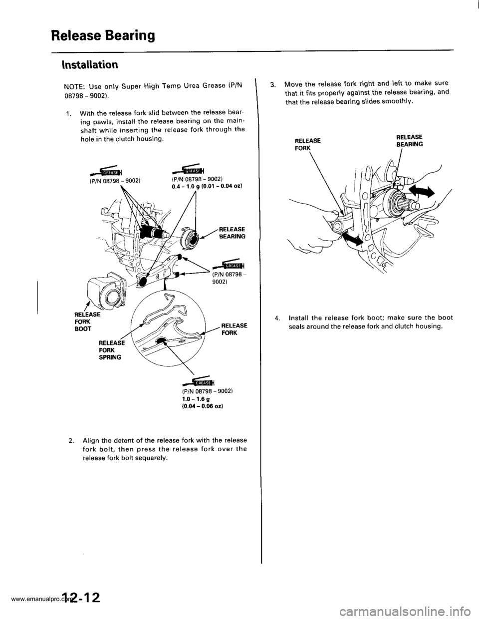
Release Bearing
lnstallation
NOTE: Use only Super High Temp Urea Grease (P/N
08798 - 9002).
1. With the release fork slid bet\iveen the release bear-
ing pawls. install the release bearing on the main-
shaft while inserting the release tork through the
hole in the clutch housing.
lPlN 08798 - 9002)0.,1- 1.0 I (0.01 - 0 04 ozl
(P/N 087989002)
(P/N 08798 9002)
1.0 - 1.6 g
{0.0,1 - 0,06 ozl
-6.l(P/N 08798 -
r iz]))
| (,4\1t1t
/\[wRELEASEFORKBOOT
Align the detent of the release fork with the release
fork bolt, then press the release fork over the
release fork bolt sequarelv.
12-12
3. Move the release lork right and left to make sure
that it tits properly against the release bear'rng. and
that the release bearing slides smoothlY.
Install the release tork boot; make sure the boot
seals around the release fork and clutch housing.
4.
www.emanualpro.com
Page 450 of 1395
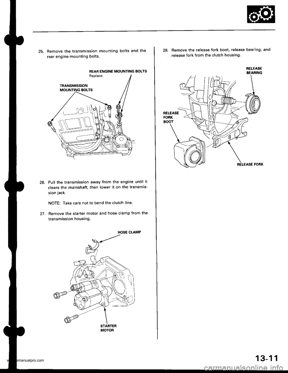
25. Remove the transmission mounting bolts and the
rear engine mounting bolts.
REAR ENGINE MOUNTING BOLTSReplace.
TRANSMISSION
Pull the transmission away from the engine until it
clears the mainshaft, then lower it on the transmis-
sion jack.
NOTE: Take care not to bend the clutch line.
Remove the starter motor and hose clamp from the
transmission housing.
STARTERMOTOR
28. Remove the release tork boot. release bearing, and
release fork from the clutch housing
RELEASEBEANING
13-1 1
www.emanualpro.com
Page 511 of 1395
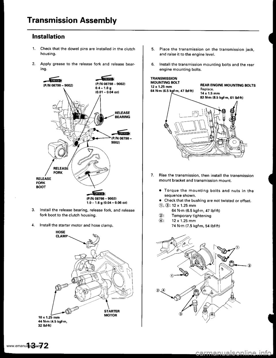
Transmission Assembly
1.
Installation
Check that the dowel pins are installed in the clutch
housing.
Apply grease to the release fork and release bear-
ing.
{P/N 08798 - 90021{P/N 08798 - 9002)0.{ - 1.0 g
{0.0'l - 0.04 ozl
RELEASEBEARING
(P/N 08798 -
9002)
RELEASEFORKBOOT
?
(P/N 08798 - 9002)'1.0 - 1.6 g {0.0,1- 0.06 o2l
Install the release bearing, release fork, and release
fork boot to the clutch housing.
Install the starter motor and hose clamp.
10 x 1.25 mm4{ N'm (4.5 kgf.m,32 tbf.ftl
13-72
HOSE
5. Place the transmission on the transmission jack,
and raise it to the engine level.
6. Install the transmission mounting bolts and the rear
engine mounting bolts.
TRANSMISSIONMOUNTING EOLT12 x 1.25 mn
7.
64 N.m {6.547 tbt.ft)
REAR ENGINE MOUNNNG BOLTSReplace.Itl x 1.5 mm8:l N.m 18.5 kgt m, 61 lbf.ft)
Rise the transmission, then install the transmission
mount bracket and transmission mount.
. Torque the mounting bolts and nuts in thesequence shown.
. Check that the bushing are not twisted or offset.
O. @: 12 x 1.25 mm
64 N.m (6.5 kgf.m, 47 lbf'ft)
O: Temporary tightening
@: 12 x 1.25 mm
74 N.m (7.5 kgf'm,54 lbf.ft)
www.emanualpro.com
Page 818 of 1395
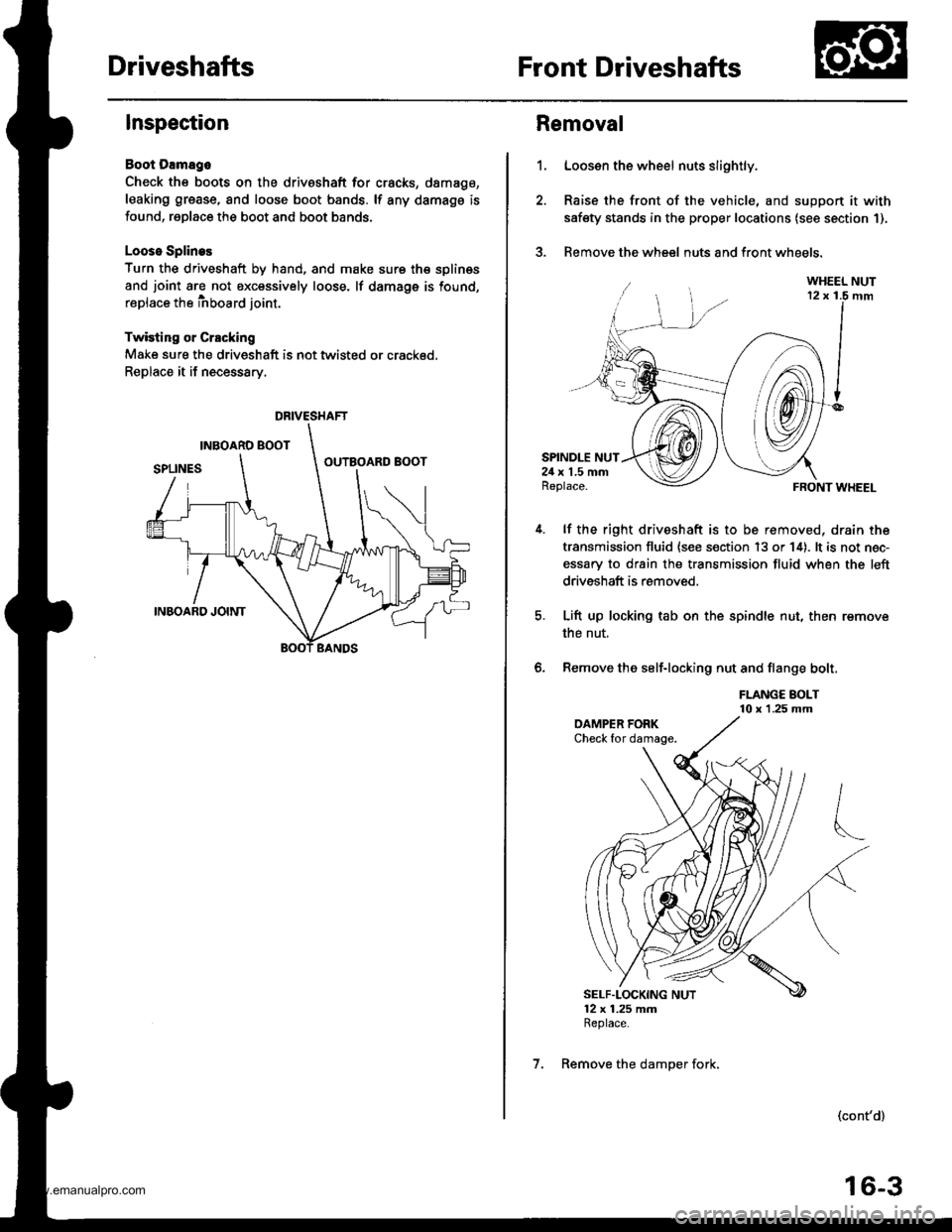
DriveshaftsFront Driveshafts
Inspection
Boot Damago
Check the boots on the driveshaft for cracks, damago,
leaking grease, and loose boot bands. lf any damags is
found, replace the boot and boot bands.
Looso Splines
Turn the driveshaft by hand, and make sure th€ splin€s
and joint are not excessively loose. lf damage is found,
replace the inboard joint.
Twisting or Crscking
Make sure the driveshaft is not twisted or crackod.
Replace it if necessary.
DRIVESHAFT
1.
Removal
Loosen the wheel nuts slightly.
Raise the front of the vehicle, and suppon it with
safety stands in the proper locations (see section 1).
Remove the wheel nuts and front wheels.?
SPINDLE NUT24 x 1.5 mmReplace.
lf the right driveshaft is to be removed, drain the
transmission fluid {see s€ction 13 or 14). lt is not nec-
essary to drain the transmission fluid when the left
driveshaft is removed.
Lift up locking tab on the spindle nut, then remove
the nut,
Remove the self-locking nut and flange bolt,
FLANGE BOLT10 x 1.25 mm
FRONT WHEEL
(cont'd)
6.
SELF"LOCKING NUT12 x 1.25 mmReplace.
7. Remove the damper fork,
16-3
www.emanualpro.com
Page 819 of 1395
Front Driveshafts
Removal (cont'd)
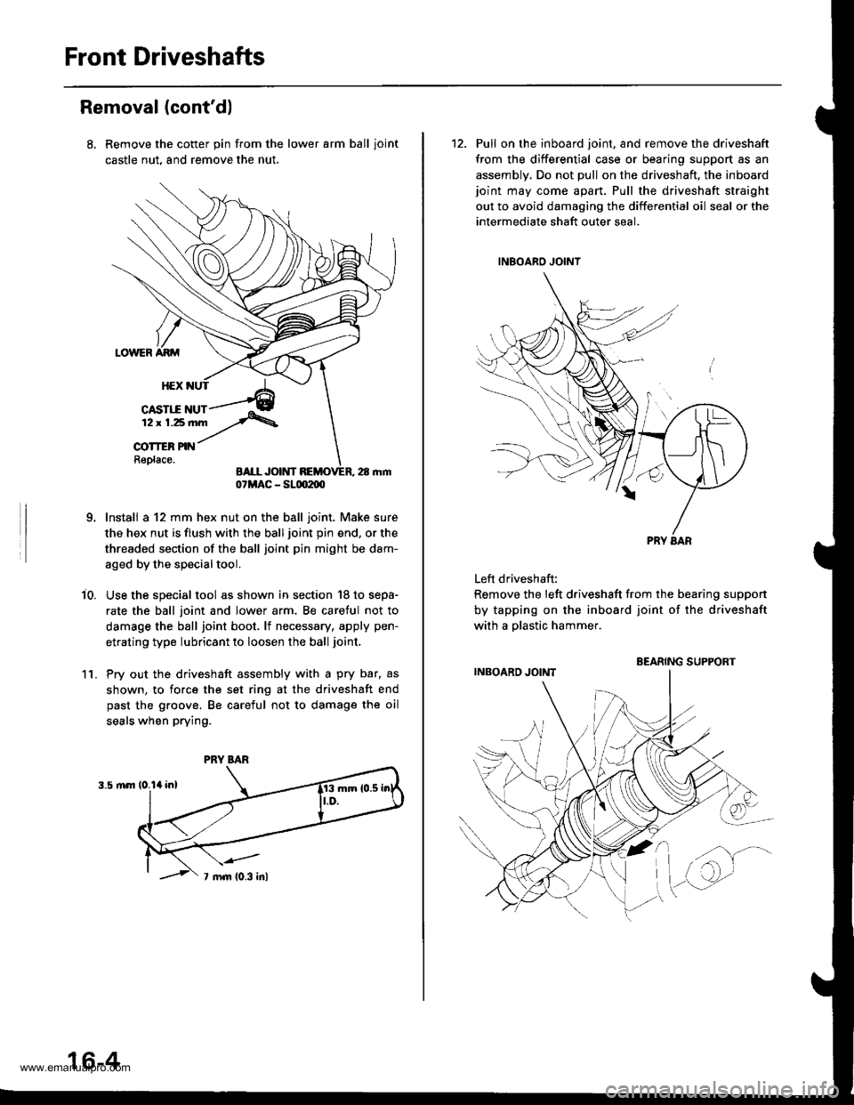
Remove the cotter pin from the lower arm ball ioint
castle nut, and remove the nut.
Install a 12 mm hex nut on the ball joint. Make sure
the hex nut is flush with the ball joint pin end, or the
threaded section of the ball joint pin might be dam-
aged by the special tool.
Use the special tool as shown in section '18 to sepa-
rate the ball joint and lower arm, Be caretul not to
damage the ball joint boot, lf necessary, apply pen-
etrating type lubricant to loosen the ball joint,
Pry out the driveshaft assembly with a pry bar, as
shown, to force the set ring at the driveshaft end
past the groove. Be careful not to damage the oil
seals when prying.
i0.
1l.
07MAC - SLm2m
PRY BAR
16-4
12. Pull on the inboard joint, and remove the driveshaft
from the differential case or bearing support as an
assembly. Do not pull on the driveshaft, the inboardjoint may come apart. Pull the driveshaft straight
out to avoid damaging the differential oil seal or the
intermediate shaft outer seal.
Left driveshaft:
Remove the left driveshaft from the bearing suppon
by tapping on the inboard joint of the driveshaft
with a olastic hammer.
BEARING SUPPORT
www.emanualpro.com
Page 820 of 1395
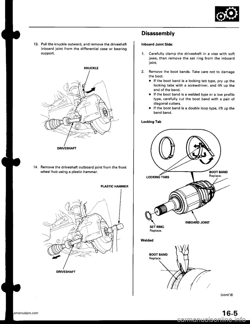
13, Pull the knuckle outward, and remove the driveshaft
inboard joint from the differential case or bearing
suoDort.
KNUCKLE
Remove the driveshaft outboard joint from the front
wheel hub using a plastic hammer.
PLASTIC HAMMER
14.
DRIVESHAFT
DRIVESHAFT
Disassembly
Inboard Joint Sid€:
1, Carefully clamp the driveshaft in a vise with softjaws, then remove the set ring from the inboardjoint.
2. Remove the boot bands. Take care not to damage
the boot,
. lf the boot band is a locking tab type, pry up the
locking tabs with a screwdriver, and lift up the
end of the band.
. lf the boot band isawelded typeora low profile
type, carefully cut the boot band with a pair of
diagonal cutters.
. lf the boot band is a double loop type. lift up the
band bend.
Locking Tab
SET BINGReplace.
Welded
{cont'd)
16-5
www.emanualpro.com