four wheel drive HONDA CR-V 1997 RD1-RD3 / 1.G User Guide
[x] Cancel search | Manufacturer: HONDA, Model Year: 1997, Model line: CR-V, Model: HONDA CR-V 1997 RD1-RD3 / 1.GPages: 1395, PDF Size: 35.62 MB
Page 1325 of 1395

Troubleshooting
Erasing the DTC Memory
To erase the DTC{S) from the SRS unit, use a Honda
PGM Tester (see the Honda PGM Tester SRS Vehicle
System Supplement) or the following procedure.
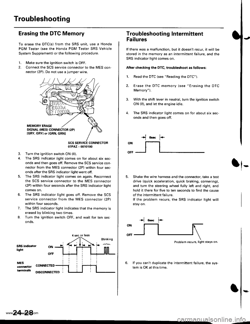
1. Make sure the ignition switch is OFF.
2. Connect the SCS service connector to the MES con,
nector (2P). Do not use a jumper wire.
MEMORY ERASESIGNAL (MES} CONNECTOR I2PIIGRY, GRYI or IGRN, GRNI
SCS SERVICE CONNECTOR07PAZ - 0010100
3. Turn the ignition switch ON (ll),
4. The SRS indicator light comes on for about six sec-
onds and then goes off. Remove the SCS servjce con
nector from the MES connector {2P) within four sec-
onds after the SRS indicator light went otf.
5. The SRS indicator light comes on again. Reconnect
the SCS service connector to the MES connector(2P) within four seconds after the SRS indicator lioht
comes on,
6. The SRS indicator light goes otf. Remove the SCS
service connector from the MES connector (2P)
within four seconds.
7. The SRS indicator light indicates that the memory is
erased by blinking two times.
L Turn the ignition switch OFF, and wait for ten sec
onos.
SRS indicatorliqtfi
MESconnac'lolterminals
OFF
CONNECTED
OISCONNECTEO
24-28
,l sec or less
3.
Troubleshooting Intermittent
Failures
lf there was a malfunction. but it doesn't recur, it will be
stored in the memory as an intermittent failure, and the
SRS indicator light comes on.
After checking the DTC, troubleshoot as follows:
1. Read the DTC (see "Reading the DTC").
4.
Erase the DTC memory (see "Erasing the DTC
Memory").
With the shift lever in neutral, turn the ignition switch
ON (ll), and let the engine idle.
The SRS indicator ljght comes on for about six sec-
onds and then goes off.
t*F
ON
lt--- _l
Shake the wire harness and the connector, take a test
drive (quick acceleration, quick braking, cornering),
and turn the steering wheel fully left and right, and
hold it there for five to ten seconds to find the cause
of the intermittent failure.
lf the problem recurs, the SRS indicator light will
stay on.
-+t 6!.c l.-
Problem recurs, light stays on.
6. lf you can't duplicate the intermiftent tailure, the sys-
tem is OK at this time.
:-
-4
www.emanualpro.com
Page 1392 of 1395

SRS Unit
).0Replacement
CAUTION:
. Before disconnecting any part of the SRS wire har-
nesg, disconnect the airbag connoctors (and soat beh
tensioner connectorsl.
. During installation or replacament, do not bump(impact wrench, hammer etc.) the area near the SRS
unit.
Do not damage the SFS unit terminalg or connsc-
lors.
Do not disassemble the SRS unit it has no saryice-
able parts,
Store the SRS unit in a clean, dry area.
Do not use any SRS unit which has been subiected
to water damage or shows signs ot being dropped orimproperly handlgd, such as dents, cracks or defor-
mation.
Disconnect the battery negative cable, then discon-
nect the positive cable from the battery, andwaitat
least three minutes.
Disconnect the airbag connectors (and seat belt ten-
sioner connectors). (When disconnected, the airbag
and seat belt tensioner connectors are automatical-
ly shorted.)
Driver's Side:
. Remove the access panel from the steering
wheel, then disconnect the 2P connector
between the driver's airbag and cable reel (see
page 24-231.
Front Passenger's Side:. Disconnect the 2P connector between the frontpassenger's airbag and SRS main harness (see
page 24-231.
Soat Beh Tensionor ('98 - 00 modelsr:. Remove the left and right center pillar lower trimpanels (see section 20).
. Disconnect the seat belt tensioner 2P connectors
from the left side wire harness (driver's side) and
the right wire harness (front passenger's side)(see page 24'231.
2.
a
a
'1.
)
)o
24-95
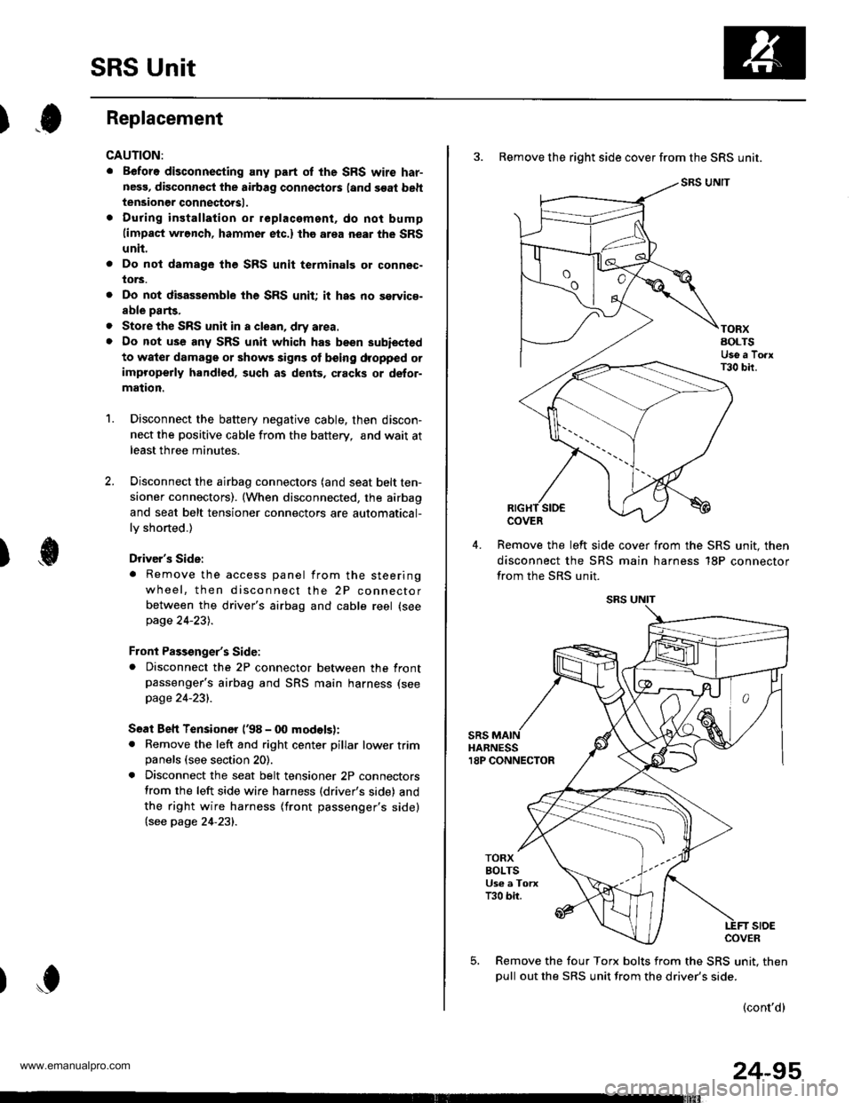
3. Remove the right side cover from the SRS unit.
SRS UNIT
TORXAOLTSUse a TorxT30 bir.
COVER
Remove the left slde cover from the SRS unit. then
disconnect the SRS main harness 18P connector
from the SRS unit.
sRsHARNESS18P CONNECTOR
TORXBOLTSUs€ a TorxT30 bir.
stoECOVER
Remove the four Torx bolts from the SRS unit. then
oull out the SRS unit from the driver's side.
(cont'd)
www.emanualpro.com