air con HONDA CR-V 1997 RD1-RD3 / 1.G Workshop Manual
[x] Cancel search | Manufacturer: HONDA, Model Year: 1997, Model line: CR-V, Model: HONDA CR-V 1997 RD1-RD3 / 1.GPages: 1395, PDF Size: 35.62 MB
Page 975 of 1395
![HONDA CR-V 1997 RD1-RD3 / 1.G Workshop Manual
Troubleshooting
DTG 54: Main Relay
IWHT/GRNI
AAS CONTROL UNIT 26P CONNECTON
Wire side of female terminals
ABS COf{TROL UN]T 22P CONNECTOR
PCOMIGRN/WHTIscoM{BLK/WHTI
Wire side of female terminals
- Wi HONDA CR-V 1997 RD1-RD3 / 1.G Workshop Manual
Troubleshooting
DTG 54: Main Relay
IWHT/GRNI
AAS CONTROL UNIT 26P CONNECTON
Wire side of female terminals
ABS COf{TROL UN]T 22P CONNECTOR
PCOMIGRN/WHTIscoM{BLK/WHTI
Wire side of female terminals
- Wi](/img/13/5778/w960_5778-974.png)
Troubleshooting
DTG 54: Main Relay
IWHT/GRNI
AAS CONTROL UNIT 26P CONNECTON
Wire side of female terminals
ABS COf{TROL UN]T 22P CONNECTOR
PCOMIGRN/WHTIscoM{BLK/WHTI
Wire side of female terminals
- With the ignition switch ON(lll, the ABS indicator doesnot go off.- With the SCS service connec-tor connected {see page 19-381,DTC 54 is indicatod.
Check the ABS +B 120 A) fuse inthe under-hood ABS luse/relaybox, and reinstall the fuse if it isoK.
FeDlace the tu3e and recheck.
Ch€ck tor an open in the 81, 82circuit:Measure the voltage betweenbody ground and the ABS controlunit 26P connector terminal No. 14and No. 15 individually.
Repair open in the wiro bstweonth6 ABS conirol unit and theunder-hood ABS fuse/rolay box,
ls there battery voltage?
Check for a short to body groundin the PMR circuit:L Turn the ignition switch OFF.2. Remove the pump motor relay.3. Disconnect the ABS controlunit 22P connector.4. Check lor continuity betweenterminal No. 19 and bodygrouno.
Repair short to body ground inthe wire betweon the under-hood ABS lGe/r.lay box and theABS control unit.
Check for a short to body groundin the PCOM, SCOM cilcuit:1. Disconnect the ABS controlunit 26P connector.2. Check tor continuity betweenbody ground and the ABS con-trol unit 26P terminals No- 1and No.2 individually.
. R€pair short to body ground inth€ P1COM circuit wire betweenthe ABS control unit and theund6r-hood ABS tuse/r6layoox.. R6p.ir short to body ground inthe PCOM or SCOM circuit wirebetweon th6 ABS control unitand lhe mod!lator unit.. R.Dlece tho modulrtor unit.(Short circuit inside the unitl
ls there continuity?
(To page 19-53)
www.emanualpro.com
Page 976 of 1395
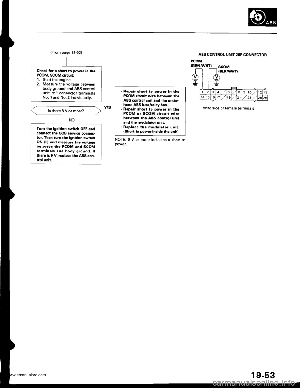
Check fo. a short to power in thaPCOM, SCOM circuhi1. Start the engine.2. Measure the voltage betweenbody ground and ABS controlunit 26P connector terminalsNo. I and No.2 individually.
'Repair short to powor in thsFCOM circuit wiro botwoon th€ABS control unit and the under-hood ABS tuse/r.lay box.. Repeir 3hort to power in thoPCOM or SCOM circuit wirebetwegn tho ABS control uniiand ths modulator unh,. R.placo tha modulatoi unit.(Shon to power in.ido th6 unitl
ls there 8 V or more?
Tu.n tho ignhion switch OFF andconnect thc SCS 3orvice connec-tor. Then turn thc ignition switchON (lll and measure tha voltagobotween the PCOM .nd SCOMtsrminal3 and body gJound. Itther6 is 0 V, .epleco tho ABS con-trol unit.
ABS CONTROL UNIT 26P CONNECTOR
PCOM
Wire side of temale terminals
NOTE: 8 V or more indicates a short to
(GRN/WHTI SCOM
www.emanualpro.com
Page 980 of 1395
ABS Control Unit
Pulsers/Wheel
Sensors
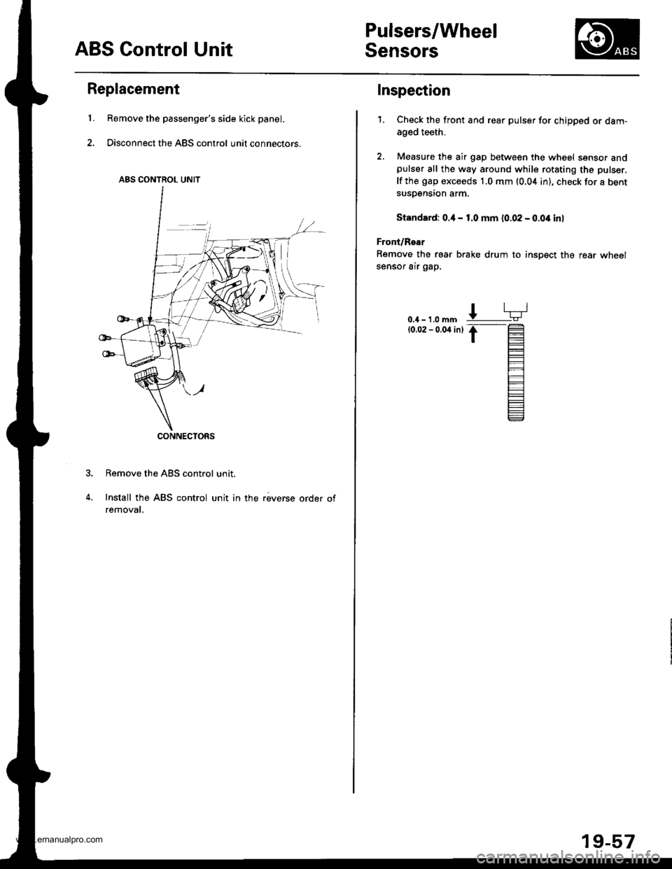
Replacement
Remove the passenger's side kick panel.
Disconnect the ABS control unit connectors.
Remove the ABS control unit.
Install the ABS control unit in the reverse order ofremovat.
ABS CONTROL UNIT
CONNECTORS
L
Inspection
1.Check the front and rear pulser for chipped or dam-
aged teeth.
Measure the air gap between the wheel sensor andpulser all the way around while rotating the pulser.
lf the gap exceeds 1.0 mm (0.04 in), check for a bentsusDension arm.
Standard: o.il - 1.0 mm 10.02 - 0.04 inl
Front/Rear
Remove the rear brake drum to insDect the rear wheolsensor air gap,
0.4 - 1.0 mm(0.02 - 0.04 inl
19-57
www.emanualpro.com
Page 983 of 1395
Doors
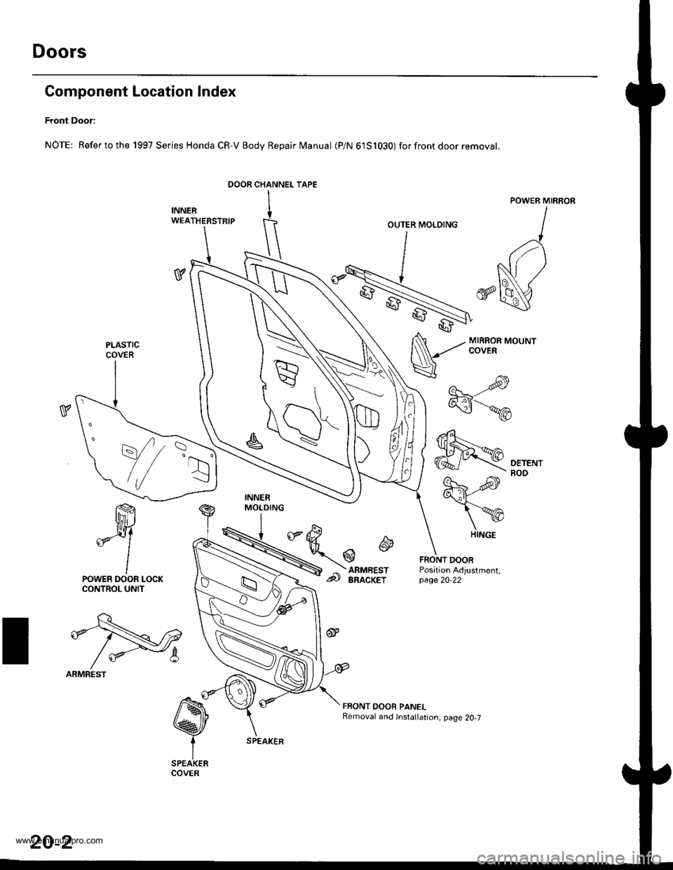
Component Location Index
Front Door:
NOTE: Refertothe 1997 Series Honda CR-V Body Repair Manual (P/N 61S1030) forfrontdoor removat.
ffi
*Y
lPOWER DOOR LOCKCONTROL UNIT
t\q
efl-Nr2
/ *-8
ARMREST
OOOR CHANNEL TAPE
INNERW€ATHERSTRIP
v
MIRROR MOUNTCOVER
----s-re
"\-,-.*
€fl
FRONT DOORPosition Adjustment,page 20-22
FRONT DOOR PANELRemoval and lnstallation, page 20,7
OUTER MOLDING
PLASTICCOVER
,.r=R
\//
::r
HINGE
20-2
www.emanualpro.com
Page 985 of 1395
Doors
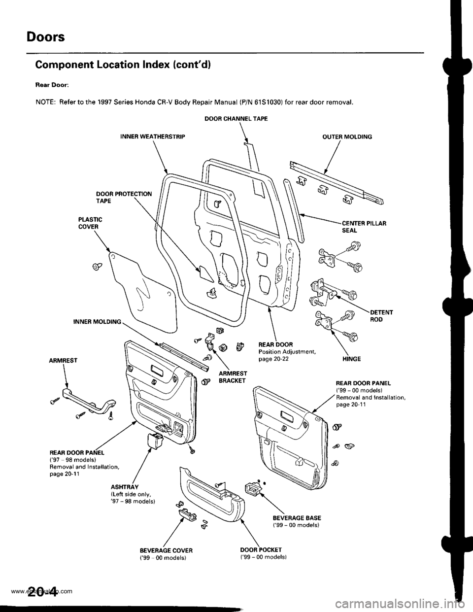
Gomponent Location Index (cont'dl
Rear Door:
NOTE: Refertothe 1997 Series Honda CR-V Bodv RepairManual (P/N 6151030) for rear door removal.
INNER WEATHERSTRIPOUTER MOLOING
DOOR PROTECTION
ARMREST
REAR DOOR('97 -98 models)
HINGE
REAR DOOR PANEL1'99 - 00 models)Removal and Installation,page 20 '11
@
ARMRESTBRACKET
Position Adiustment,page 20-22
tu4
dP
@
o
@
Bemoval and Installation,page 20-11
(Left side only,'97 - 98 models)
\
DOOR CHANNEL TAPE
FR,
)Ei
D\
\a
20-4
('99 - 00 models)
www.emanualpro.com
Page 987 of 1395
Doors
Component
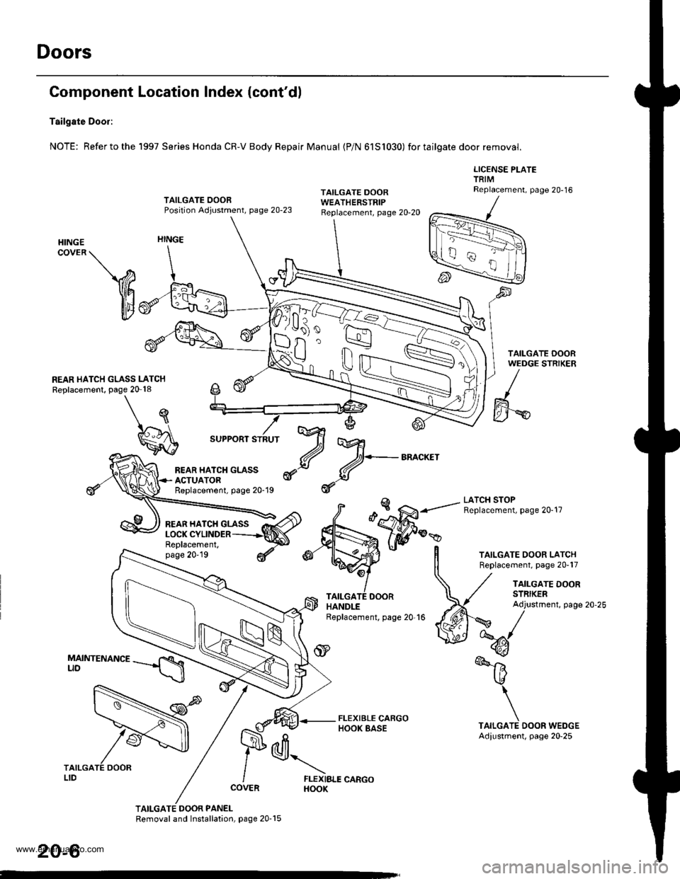
Tailgate Door:
NOTE: Refer to the
Location Index (cont'dl
1997 Series Honda CR-V Body Repair Manual {P/N 61S1030) for tailgate door removal.
LICENSE PLATETRIMReplacement, page 20-16TAILGATE OOORPosition Adjustment, page 20-23
TAILGATE DOORWEATHERSTRIP
HINGECOVER \
V
illt
REAR HATCH GLASS LATCHReplacement, page 20 18
HINGE
\
I
SUPPORT STRUT
€\A
LATCH STOPReplacement, page 20-17
Replacement,page 20'19
TAILGATE DOOR PANELRemoval and Installation, page 20-15
TAILGATE DOOR LATCHReplacement, page 20-17
TAILGATE DOORHANDLEReplacement, page 20-16
TAILGATE DOORSTRIKERAdjustment, page 20-25
k@/
%
-6
\
TAILGATE DOOR WEDGEAdiustment, page 20-25
N
REAR HATCH GLASSACTUATORReplacement, page 20-19
REAR HATCH GLASS
lVr
d+-BA^cKEr
d
d\
FLEXIBLE CARGOHOOK
20-6
www.emanualpro.com
Page 1015 of 1395
Glass
Windshield Replacement (cont'dl
17. With a sponge, apply a light coat of body primer to
the original adhesive remaining around the wind-
shield opening flange, Let the body primer dry for
at least 10 minutes.
NOTE:
. Do not apply glass primer to the body, and be care-
ful not to mix up glass and body prjmer sponges.
. Never touch the primed surfaces with your hands.
. Mask off the dashboard before painting the flange.
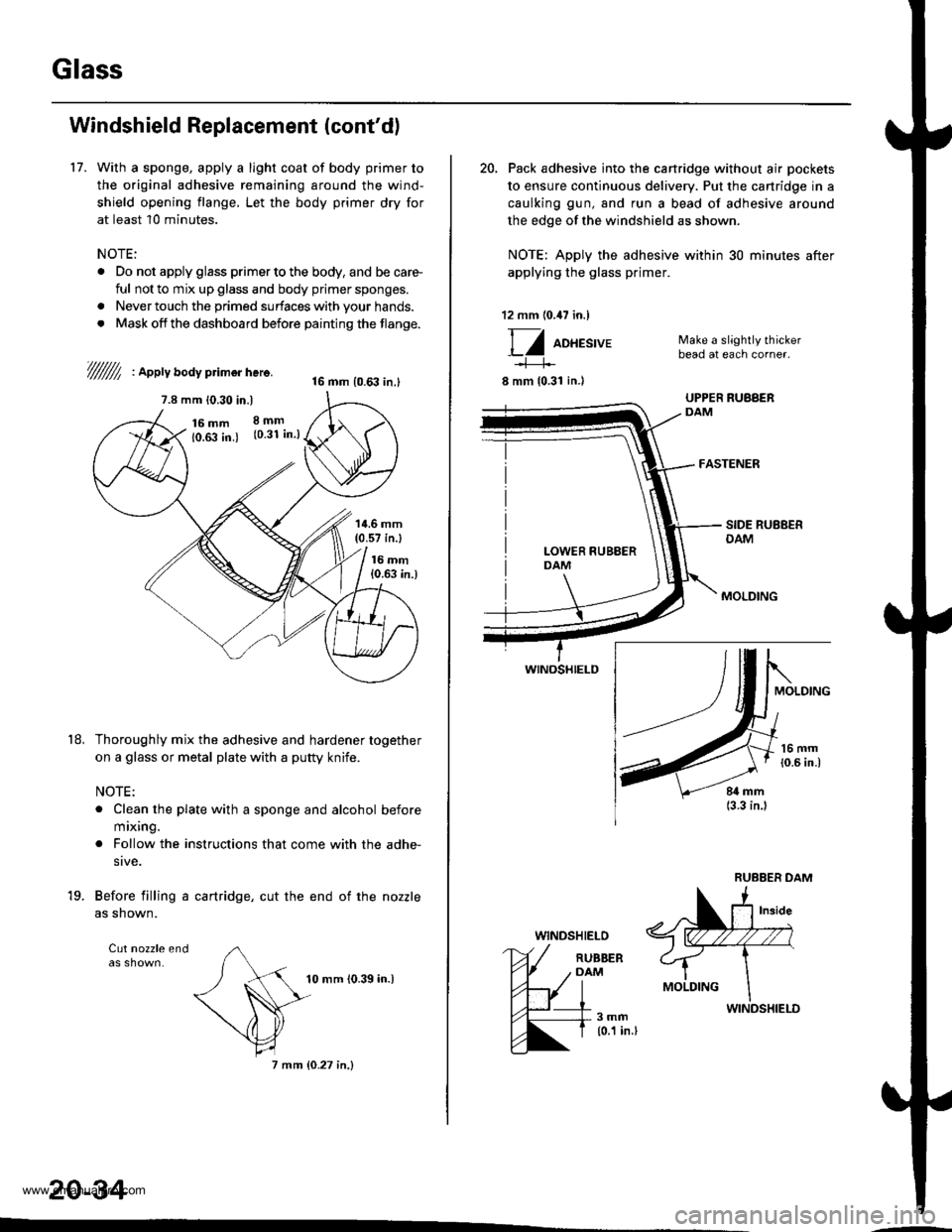
///////l , apptv aoav primor here.16 mm {0.63 in.l
7.8 mm 10.30 in.)
16 mm10.fi in.)
8mm(0.31 in.)
't8,
14.6 mm(0.57 in.l
16 mm{0.63 in.)
Thoroughly mix the adhesive and hardener together
on a glass or metal plate with a putty knife.
NOTE:
. Clean the plate with a sponge and alcohol before
mixing.
. Follow the instructions that come with the adhe-
sive.
Before filling a cartridge, cut the end of the nozzle
as shown.
Cut nozzle end
'19.
10 mm {0.39 in.)
7 mm {0.27 in,}
20-34
20, Pack adhesive into the cartridge without air pockets
to ensure continuous delivery. Put the cartridge in a
caulking gun, and run a bead of adhesive around
the edge of the windshield as shown.
NOTE: Apply the adhesive within 30 minutes after
applying the glass primer.
12 mm (0.47 in.)
Ff oo*tt'u'
8 mm {0.31 in.l
WINOSHIELD
WINDSHIELO
Make a slightly thickerbead at each corner.
FASTENER
RUBBERDAM
3mm{0.1 in.l
www.emanualpro.com
Page 1020 of 1395
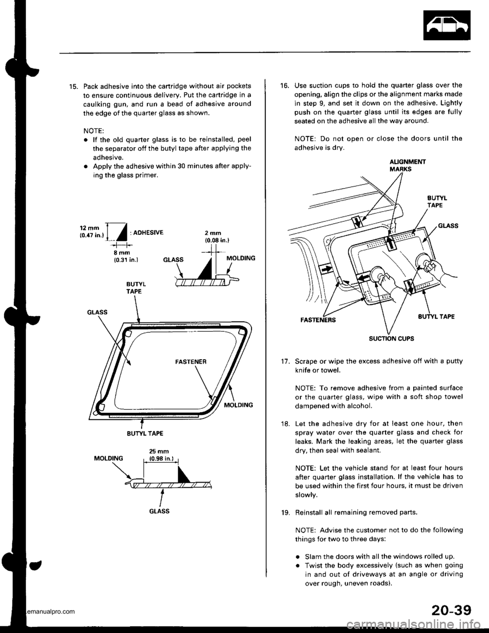
15. Pack adhesive into the cartridge without air pockets
to ensure continuous delivery, Put the canridge in a
caulking gun, and run a bead of adhesive around
the edge of the quarter glass as shown.
NOTE:
. lf the old quarter glass is to be reinstalled, peel
the separator off the butyl tape after applying the
adhesive.
. Apply the adhesive within 30 minutes after apply-
ing the glass primer.
i:.8T".,1,/:AoHEsrvE
I rnm(0.31 in.)
BUTYLTAPE
GLASS19.
20-39
16. Use suction cups to hold the quarter glass over the
opening, align the clips or the alignment marks made
in step 9, and set it down on the adhesive. Lightly
push on the quaner glass until its edges are fully
seated on the adhesive all the way around.
NOTE: Do not open or close the doors until the
adhesive is drv.
Scrape or wipe the excess adhesive off with a putty
knife or towel,
NOTE: To remove adhesive from a painted surface
or the quarter glass, wipe with a soft shop towel
dampened with alcohol.
Let the adhesive dry for at least one hour. then
spray water over the quarter glass and check for
leaks. Mark the leaking areas, let the quarter glass
dry, then seal with sealant.
NOTE: Let the vehicle stand for at least four hours
after quarter glass installation. lf the vehicle has to
be used within the first four hours, it must be driven
slowly.
Reinstall all remaining removed parts.
NOTE: Advise the customer not to do the following
things for two to three days:
. Slam the doors with all the windows rolled up.
. Twist the body excessively (such as when going
in and out of driveways at an angle or driving
over rough, uneven roads).
11.
18.
AUGNMENT
SUCTION CUPS
www.emanualpro.com
Page 1021 of 1395
lnterior Trim
20-40
CARGO FRONTSPACER(see page 20 43)
FRONT PILLARTRIM(see page 20-41)
TRUNK FLOOREXTENSION(see page 20 43)
HEADLINERRemoval and lnstallation,page 20-44
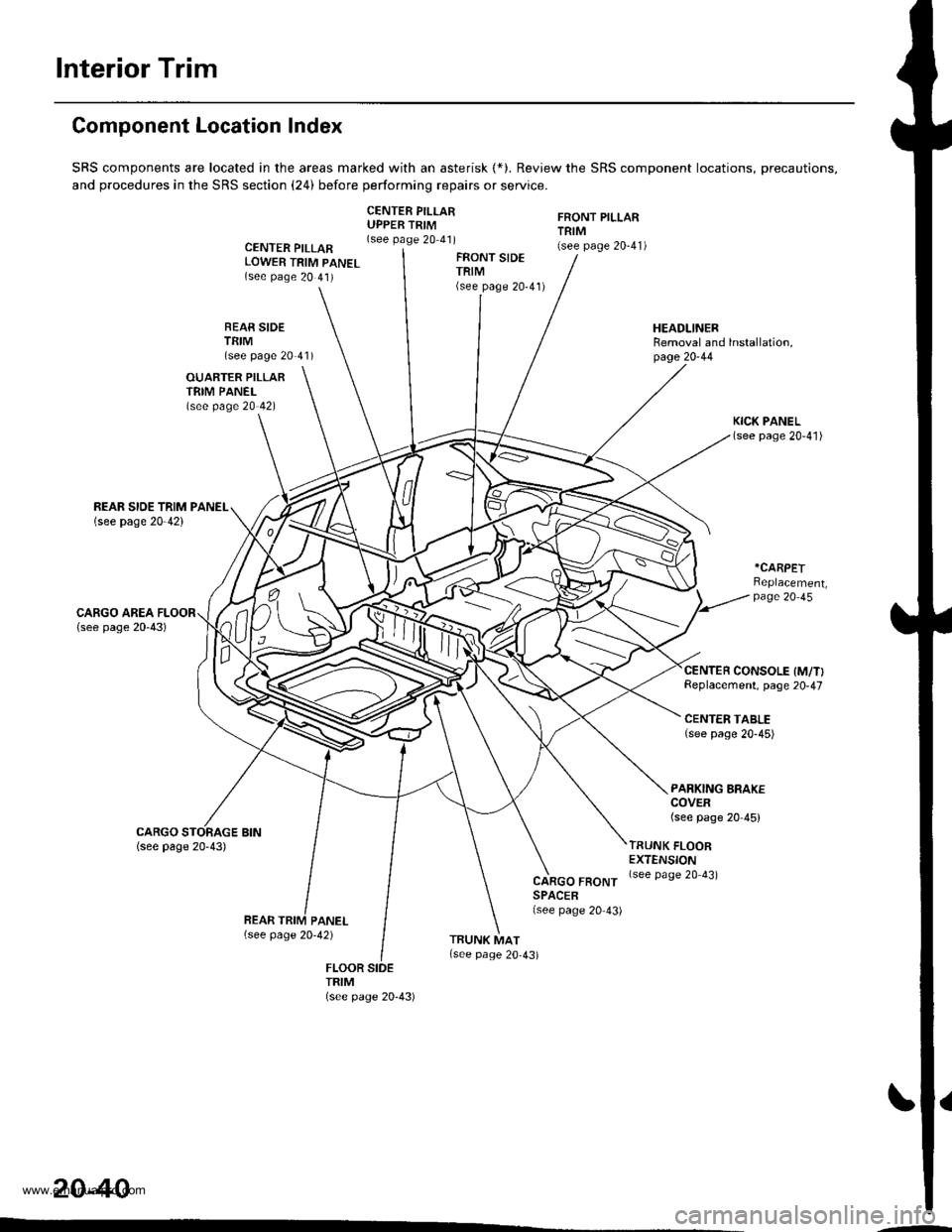
Component Location Index
SRS components are located in the areas marked with an asterisk (*). Review the SRS component locations, precautions,
and procedures in the SRS section (24) before performing repairs or service.
CENTER PILLARUPPER TRIM(see page 20 41)CENTER PILLARLOWER TRIM PANEL(see page 20 41)
FRONT SIDETRIM(see page 20-41)
BEAR SIDETEIM(see page 20'41)
OUARTER PILLARTRIM PANEL(see page 20 42)
*CARPET
Replacement,page 20 45
CENTER CONSOLE IM/T}Replacement, page 20-47
CENTEN TABLE(see page 20-45)
PARKING BRAKECOVER(see page 20-45)
TRIM
www.emanualpro.com
Page 1026 of 1395
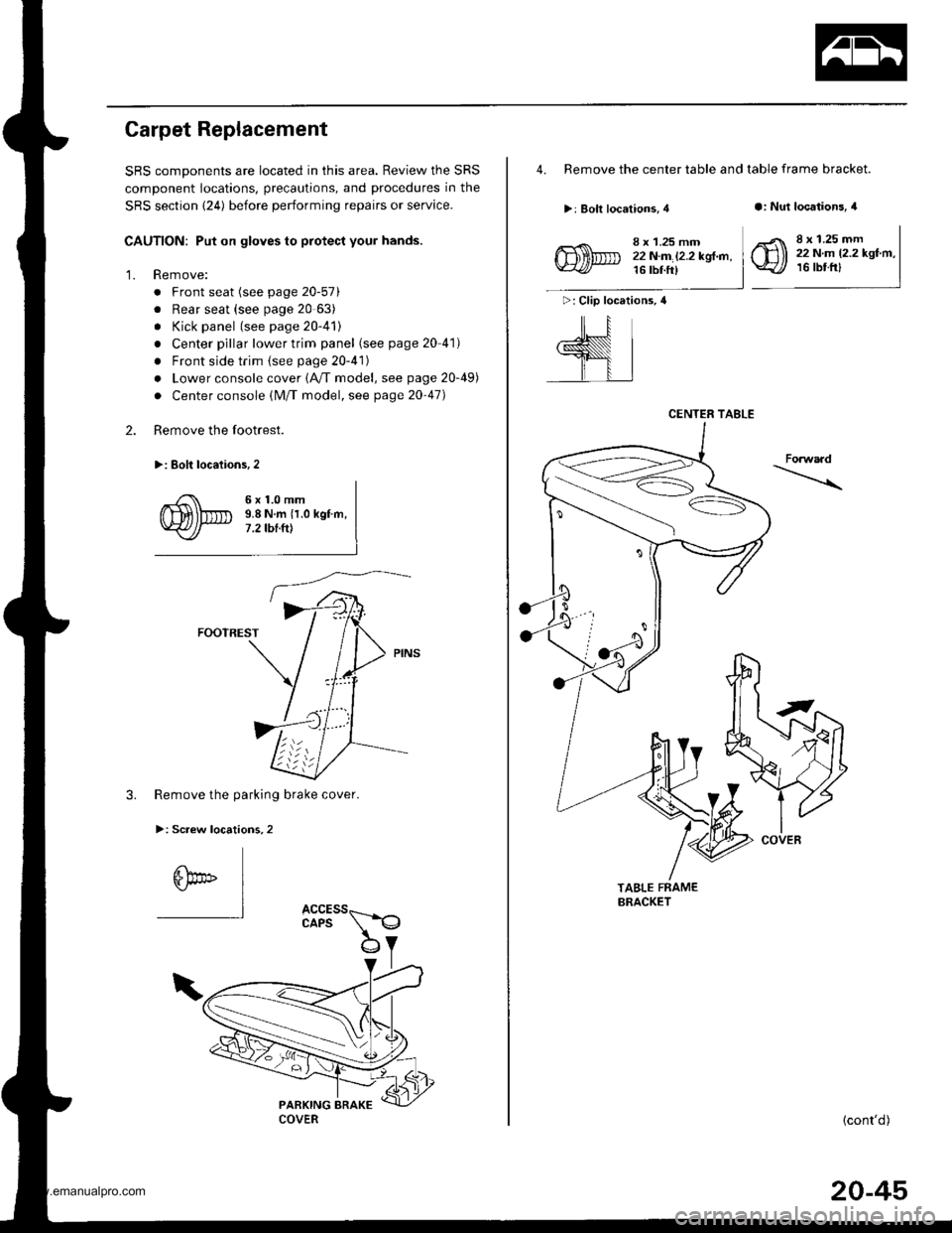
Carpet Replacement
SRS comDonents are located in this area. Review the SRS
component locations, precautions, and procedures in the
SRS section {24) before performing repairs or service.
CAUTION: Put on gloves to protect your hands.
Remove:
. Front seat (see page 20-571
. Rear seat (see page 20 63)
. Kick panel (see page 20-41)
. Center pillar lower trim panel (see page 20 41)
. Front side trim {see page 20-41)
. Lower console cover 1A,/T model, see page 20-49)
. Center console (lM/T model, see page 2o-47)
Remove the footrest.
>: Eolt locaiions,2
2.
'1.
6x1.0mm9.8 N.m {1.0 kgf.m,7 .2 tbt.ttt
FOOTREST
3. Remove the parking brake cover.
>: Screw locations,2
6bo" I"l
4. Remove the center table and table frame bracket.
>: Bolt locations, 4a: Nut locations, 4
>: Clip locations, 4
ill
,l
8 x 1.25 mm22N.m l2.2kgl.n,16 tbt ft)
8 x 1.25 mm22 N.m 12.2 kgf.m,16 tbtfrl
Forwaad
TABLE FRAMEBRACKET
{cont'd)
CENTER TABLE
COVER
20-45
www.emanualpro.com