Installation HONDA CR-V 1997 RD1-RD3 / 1.G Owner's Manual
[x] Cancel search | Manufacturer: HONDA, Model Year: 1997, Model line: CR-V, Model: HONDA CR-V 1997 RD1-RD3 / 1.GPages: 1395, PDF Size: 35.62 MB
Page 168 of 1395
Crankshaft
12.
Installation (cont'd)
14.
13.
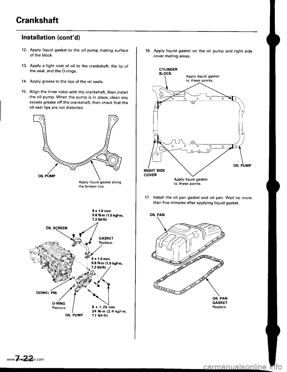
Apply liquid gasket to the oil pump mating surfaceof the block.
Apply a light coat of oil to the crankshaft, the lip ofthe seal, and the O-rings.
Apply grease to the lips of the oil seals.
Align the inner rotor with the crankshaft, then installthe oil pump. When the pump is in place, clean anyexcess grease off the crankshaft, then check that theoil seal lips are not distoned.
6x1,0mm9.8 N.m {1.0 kg{.m,,.2 tbf.ftl
I
{/^ I GASKET(..6 Replace."[z
O-RINGReplace.
OIL PUMP
6x1.0mm9,8 N.m 11.0 kg{.m,7.2lbt.trl
8 x 1.25 mm24 N.m {2.4 kgf.m,17 tbt.ftl
7 -22
,'t ./o,DowEL PtN
// |
16.Apply liquid gasket on
cover matrng areas.
CYLINDERBLOCK
the oil pump and right side
Apply liquid g€sketto these pornts.
17. Install the oil pan gasket and oil pan. Wait no
than five minutes after applying liquid gasket.
OIL PAN
OIL PANGASKETReplace.
Apply liquid gasketto these pornts,
www.emanualpro.com
Page 170 of 1395
Oil Seals
Installation (cont'dl
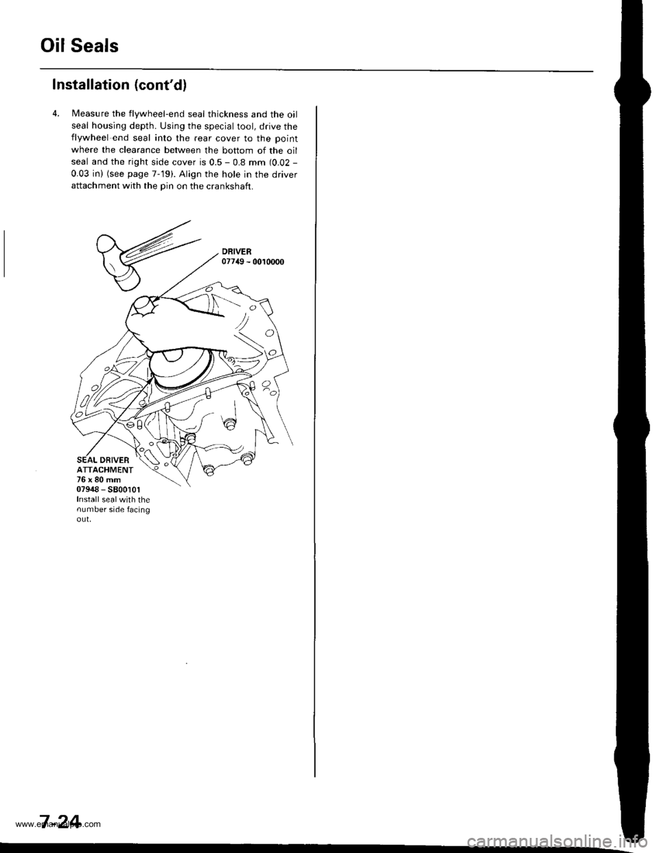
4. l/easure the flywheel-end seal thickness and the oil
seal housing depth. Using the special tool, drive theflywheel end seal into the rear cover to the point
where the clearance between the bottom of the oil
seal and the right side cover is 0.5 - 0.8 mm (0.02 -
0.03 in) (see page 7-19). Align the hole in the driverattachment with the pin on the crankshaft.
DRIVERATTACHMENT76x80mm07948 - 5800101Install sealwith thenumber side facingout,
<:
7 -24
www.emanualpro.com
Page 176 of 1395
Oil Filter
Replacement (cont'd)
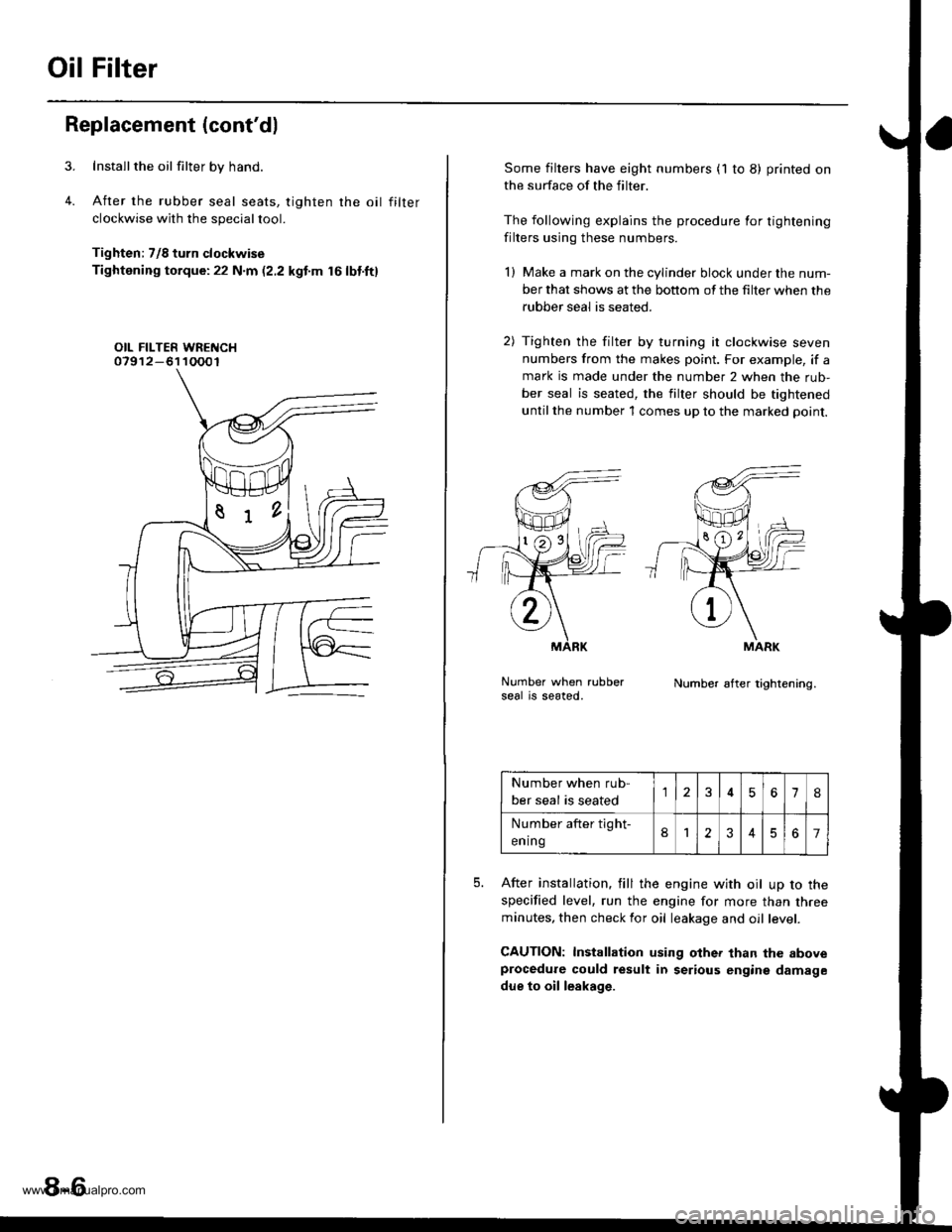
Installthe oil filter by hand.
After the rubber seal seats, tighten rhe oil filter
clockwise with the special tool.
Tighten: 7/8 turn clockwise
Tightening torque:22 N.m (2.2 kgt'm 16lbt.ft)
OIL FILTER WRENCH07912-61 10001
8-6
Some filters have eight numbers (1 to 8) printed on
the surface of the filter.
The following explains the procedure for tightening
filters using these numbers.
l) Make a mark on the cylinder block under the num-
ber that shows at the bottom of the filter when the
rubber seal is seated.
2) Tighten the filter by turning it clockwise seven
numbers from the makes point. For example, if a
mark is made under the number 2 when the rub-
ber seal is seated, the filter should be tightened
until the number 1 comes up to the marked point.
Number when rubberseal is seated.Number af ter tightening.
5.After installation. fill the engine with oil up to the
specified level, run the engine for more than threeminutes, then check for oil leakage and oil level.
GAUTION: Installation using other than the aboveprocedure could result in serious engine damage
due to oil leakage.
MARK
Number when rub-
ber seal is seated567IJ
Number after tight-
ening8123467
www.emanualpro.com
Page 208 of 1395
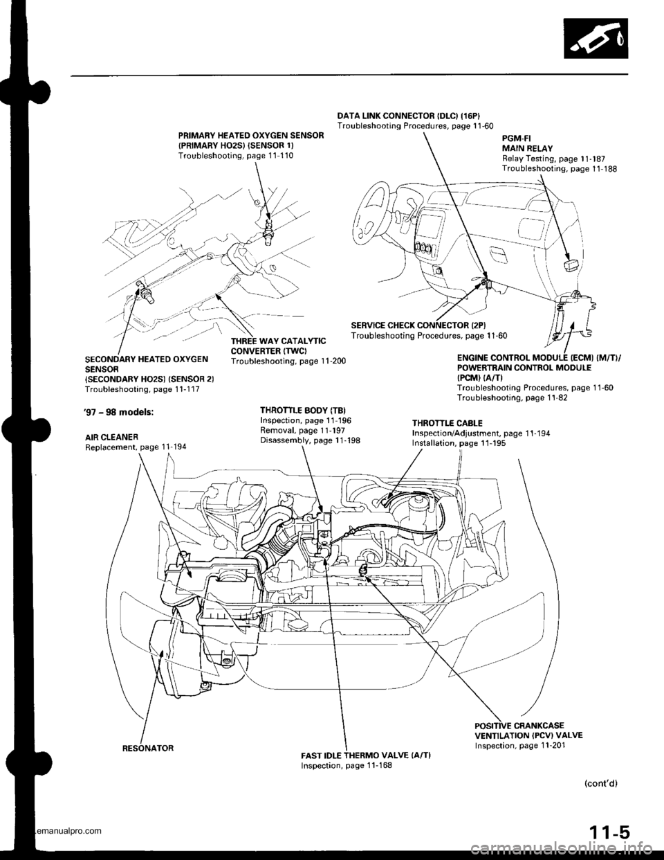
DATA LINK CONNECTOR {DLC) I16P}Troubleshooting Procedures, page 1 1'60PRIMARY HEATED OXYGEN SENSOR
{PRIMARY HO2SI {SENSOR 1)Troubleshooling, page 11 110
SECONDARY HEATED OXYGENSENSOR{SECONDARY HO2S) {SENSOR 2)Troubleshooting, page 1 1-1 17
'97 - 98 models:
AIR CLEANERReplacement, page 1 1'194
Troubleshooting, page 1 'l -200
THROTTLE BODY (TB)Inspection, page 11 196Removal, page 11-197Disassembly, page 1 1-'198
POWERTRAIN CONTROL MODULE(PCM) (A/TI
Troubleshooting Procedures, page 1 1-60Troubleshooting. page 1 1'82
THROTTLE CABLEInspection/Adjustment, page 1 1-1 94Installation, page 11- 195
VENTILATION (PCV) VALVEInspection, page 1 1-201FAST IDLEVALVE (A/T}
(cont'd)
1 1-5
PGM-FIMAIN RELAYRelay Testing, page 11-l87Troubleshooting. page 1'1 188
SERVICE CHECK CONNECTOR {2PITroubleshooting Procedures, page 1 1-60
,a'=_-_
WAY CATALYTIC
Inspection, page 1 1-168
www.emanualpro.com
Page 209 of 1395
Component Locations
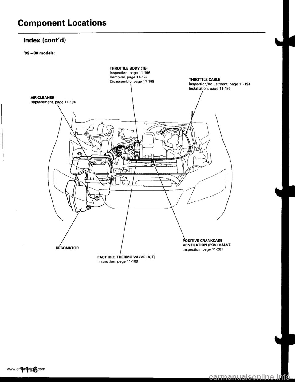
Index {cont'd)
39 - q, models:
THROTTLE BODY ITB)Inspection, page 1 1-196Removal, page 11- 197Disassembly, page 11 198THROTTLE CABLEInspectaon/Adjustment, page 1 1 194Installation, page I l'195
AIR CLEANERR€placomenl, page 1 1-194
CRANKCASEVENTILATION IFCVI VALVElnspection, page 11 201
FAST IDLE THERMO VALVE IA/T)Inspection, page 11'168
1 1-6
www.emanualpro.com
Page 430 of 1395
lllustrated Index
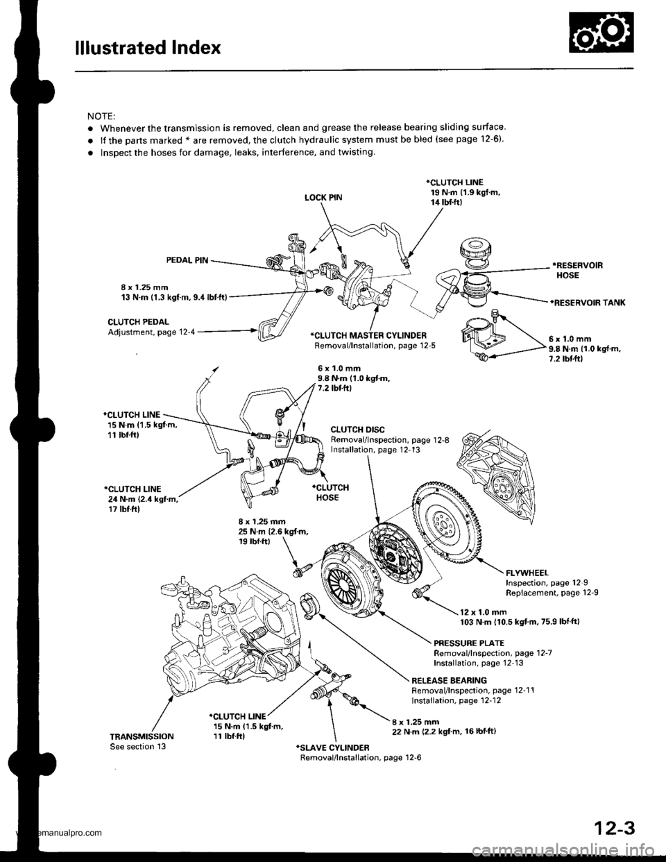
NOTE:
. Whenever the transmission is removed, clean and grease the release bearing sliding surface
.lfthepansmarked*areremoved,theclutchhydraulicsystemmustbebled(seepage1\
2-6).
. Inspect the hoses for damage. leaks. interference, and twisting.
LOCK PIN
*CLUTCH LINE19 N.m (1.9 kgj.m,14 tbtft)
8 x 1.25 mm13 N.m {1.3 kgf m,9.4lbtft)
PEDAL PIN.RESEFVOIR
HOSE
*RESERVOIR TANK
CLUTCH PEDALAdjustment, page 12-4*CI-UTCH MASTER CYLINDERFemoval/lnstallation, page 12-5
6x1.0mm9.8 N.m (1.0 kgf.m,7.2 tbf.ft)
*CLUTCH LINE15 N.m (1.5 kgt m,11 tbr.ft)
*CLUTCH LINE24 N.m {2.4 kgf.m,17 tbf.ft)
CLUTCH DISCRemoval/lnspection, page 1 2-8Installation, page 12,13
8 x 1.25 mm25 N.m {2.6 kgt m,19 rbf.ftt
I x 1.25 mm22 N.m 12.2 kgl'm, 16lbfft)
.o-.9r
WM\,".0--
ffi-P"8Nmlloks{m'
FLYWHEELInspection, page 12IRepiacement, page 12-9
12 x 1.0 mm103 N.m (10.5 kgtm,75.9 lbf ftl
PRESSURE PLATERemoval/lnspection, page'12-7
Installation, page'12 13
RELEASE BEARINGRemoval/lnspection, page 12-1'!Installation, page 12-12
*CLUTCH LINE15 N.m (1.5 kgt m,11 tbf.ft)
12-3
www.emanualpro.com
Page 437 of 1395
FlywheelClutch Disc, Pressure Plate
Replacement (cont'dl
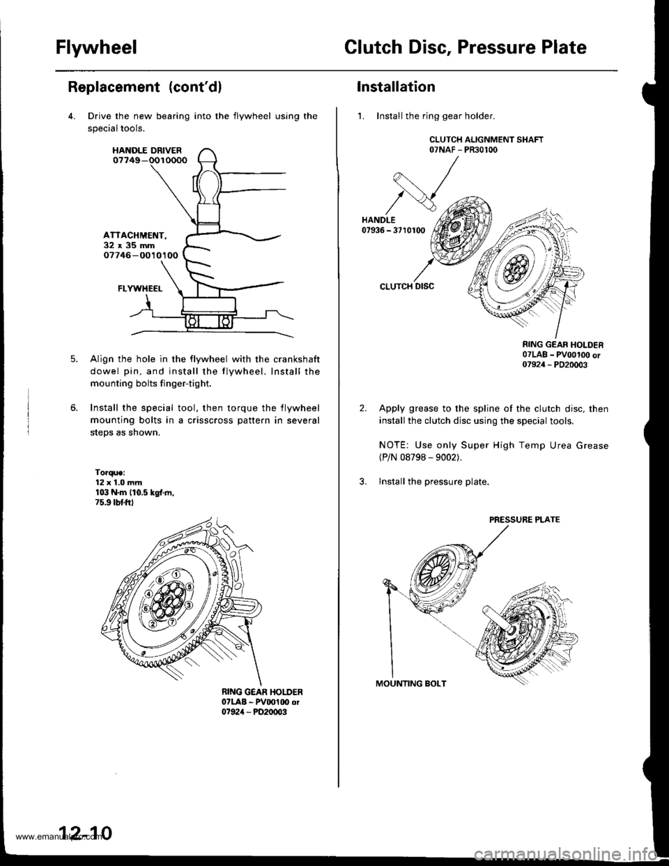
Drive the new bearing
specialtools.
HANOLE DRIVER07749-
ATTACHMET{T-32x35mm07746 -O010100
FLYWHECI-
Align the hole in the flywheel with the crankshaft
dowel pin, and install the flywheel. Install the
mounting bolts finger-tight.
Install the special tool, then torque the flywheel
mounting bolts in a crisscross pattern in several
steps as shown.
Torque:12 x 1.0 mmr03 N.m (10.5 kgl.ln,75.9 tbtftl
into the flywheel using the
12-10
Installation
1. Install the ring gear holder.
CLUTCH ALIGNMENT SHAFT07NAF - PR30100
CLUTCH DISC
RING GEAR HOLDER07LAB _ pvoot(x) or07924 _ PD20003
Apply grease to the spline of the clutch disc, then
install the clutch disc using the special tools.
NOTE: Use only Super High Temp Urea Grease(P/N 08798 - 9002).
lnstall the pressure plate.
PRESSURE PLATE
www.emanualpro.com
Page 462 of 1395
Mainshaft Assembly
lndex
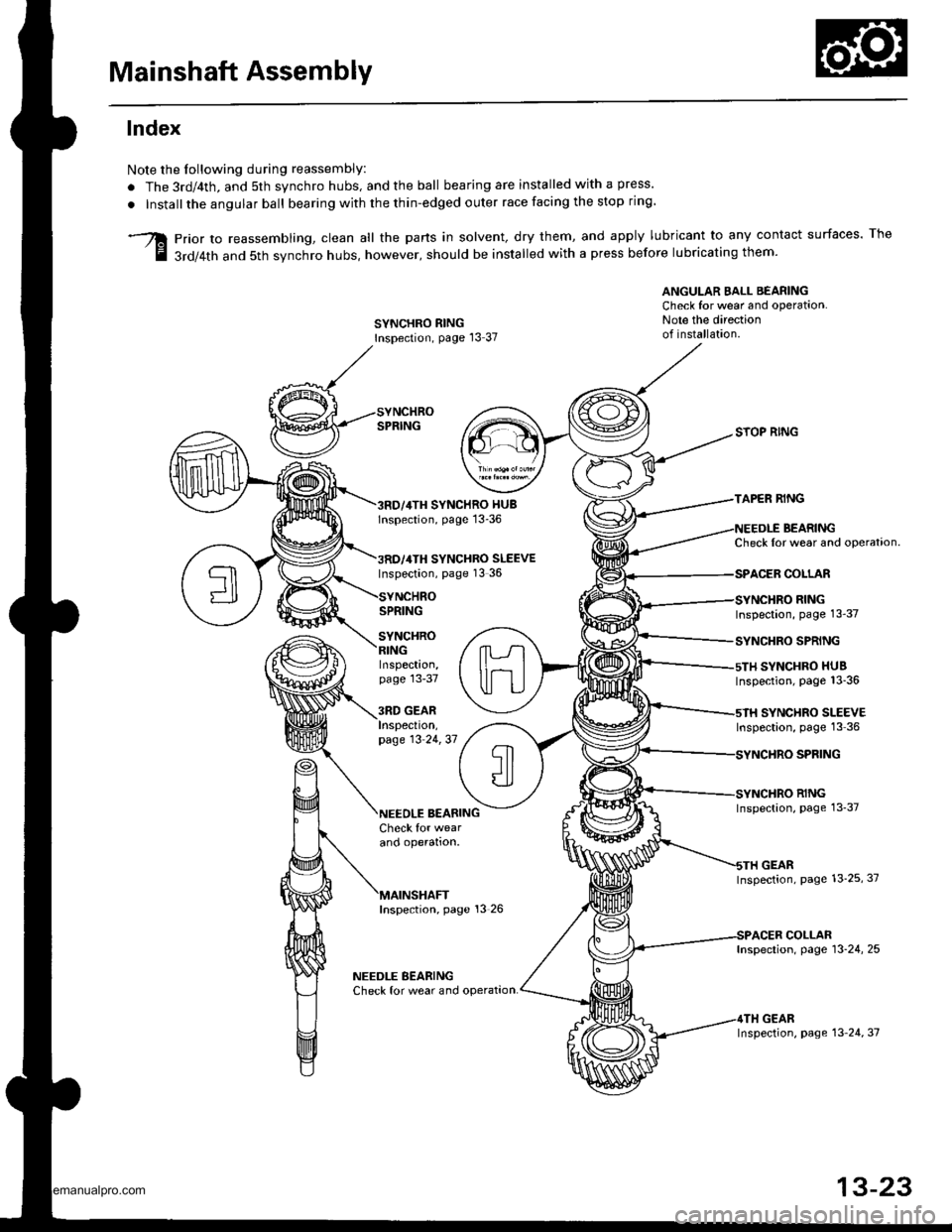
Note the Iollowing during reassembly:
. The 3rd/4th, and 5th synchro hubs, and the ball bearing are installed with a press.
. Installthe angular ball bearing with the thin-edged outer race facing the stop ring
prior to reassembling, clean all the parts in solvent, dry them, and apply lubricant to any contact surfaces. The
3rd/4th and 5th svnchro hubs, however, should be installed with a press before lubricating them'
ANGULAR EALL BEARINGCheck for wear and operation.Note the directionof installation.SYNCHRO RINGInspection, page l3 37
SYNCHRO HUBlnspection, page 13-36
SYNCHRO SLEEVEInspection, page 13 36
SPRING
SYNCHRO
SYOP RING
TAPER RING
BEARINGCheck Ior wear and operataon.
COLLAR
RINGInspection, page 13-37
SYNCHRO SPRING
SYNCHRO HUBInspection, page 13_36
SYNCHRO SLEEVEInspection, page 13 36
SPFING
RINGInspection, page 13_37
GEARInspection, page 13_25, 37
COLLARInspection, page 13-24, 25
GEARInspection, page 13 24, 37
Inspection,page 13-37
3RD GEARInspeclton,page 13 24,37
BEARINGCheck for wearano operalton.
Inspection, page 13 26
NEEDLE BEARINGCheck for wear and operat,on.
13-23
www.emanualpro.com
Page 466 of 1395
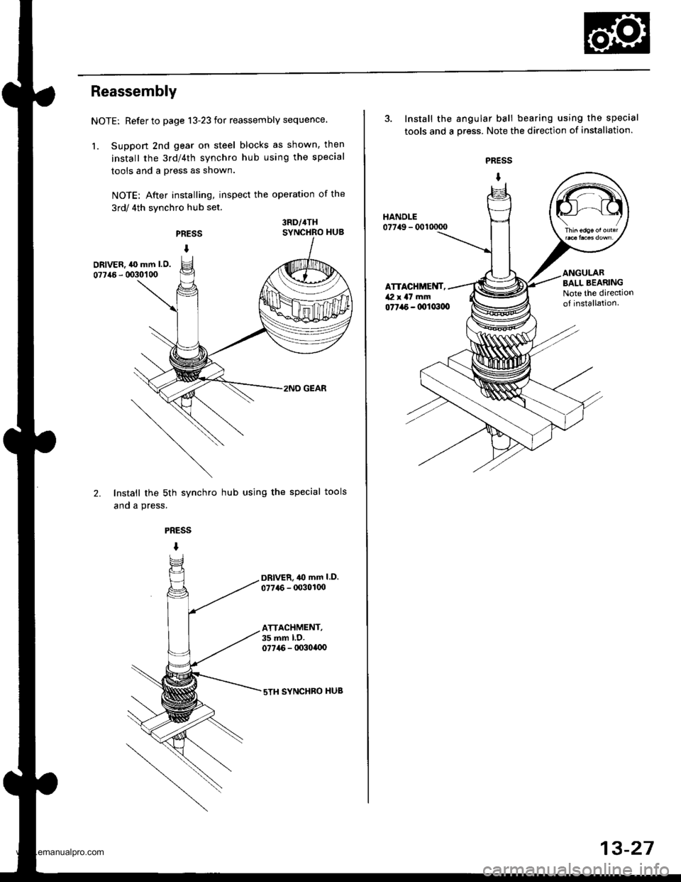
Reassembly
NOTE: Refer to page 13-23 for reassembly sequence.
1. Suppon 2nd gear on steel blocks as shown, then
install the 3rd/4th synchro hub using the special
tools and a press as shown.
NOTE: After installing, inspect the operation of the
3rd/ 4th synchro hub set.
PRESS
I
3RD/4THSYNCHRO HUB
DRIVER, ,l(} mm l.O.
07746 - 0030'�1 00
2.
2NO GEAR
Install the sth synchro hub using the special tools
and a press.
PRESS
I
DRlvER,40 mm l.D.
077{6 - 00301(x)
ATTACHMENT,35 mm l.D.077i16 - lx)3ollx)
sTH SYNCHBO HUB
3. Install the angular ball bearing using the special
tools and a oress. Note the direction of installation.
PRESS
I
077a6 - 0011x100
HANDLE07749 - 0010000
ATTACHMENT,/Vl x a7 mm
BALL BEARINGNote the dirediono{ installation.
13-27
www.emanualpro.com
Page 472 of 1395
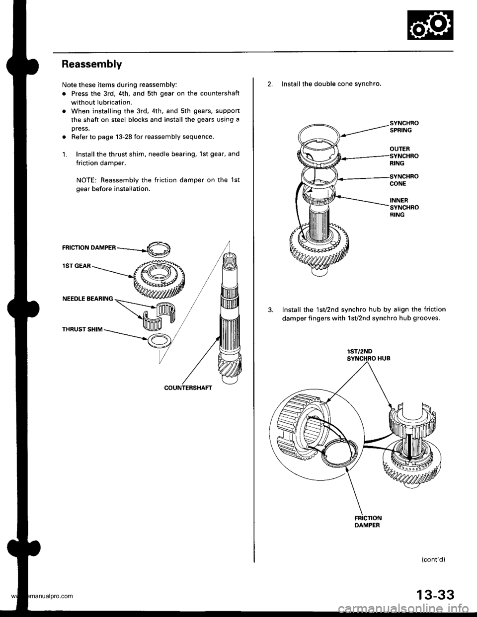
Reassembly
Note these items during reassembly:
. Press the 3rd, 4th, and sth gear on the countershaft
without lubrication.
. When installing the 3rd, 4th. and sth gears, suppon
the shaft on steel blocks and install the gears using a
press.
. Refer to page 13-28 for reassembly sequence.
1. Install the thrust shim, needle bearing, 1st gear, and
friction damper.
NOTE: Reassembly the friction damper on the lst
gear before installation.
rnrcrroru orn,leen ----.-4O)
lST GEAR
NEEDLE BEARING
THRUST SHIM
2. Install the double cone synchro.
3. Install the 1sv2nd synchro hub by align the friction
damper fingers with 1svznd synchro hub grooves.
(cont'd)
OUTER
lST/2ND
13-33
www.emanualpro.com