Motor ground HONDA CR-V 1997 RD1-RD3 / 1.G Owner's Manual
[x] Cancel search | Manufacturer: HONDA, Model Year: 1997, Model line: CR-V, Model: HONDA CR-V 1997 RD1-RD3 / 1.GPages: 1395, PDF Size: 35.62 MB
Page 1120 of 1395
![HONDA CR-V 1997 RD1-RD3 / 1.G Owners Manual
Troubleshooting
Condenser Fan {contd)
CONDENSER FAN RELAY 4P SOCKET
r---------t wHT
lr_f__l12 | |
fT;.] |I/Or\j/
I
G
CONDENSER FAN 2P CONNECTORWire side ol temale torminals
-r+-,.12
TBtK
@
!
Chock f HONDA CR-V 1997 RD1-RD3 / 1.G Owners Manual
Troubleshooting
Condenser Fan {contd)
CONDENSER FAN RELAY 4P SOCKET
r---------t wHT
lr_f__l12 | |
fT;.] |I/Or\j/
I
G
CONDENSER FAN 2P CONNECTORWire side ol temale torminals
-r+-,.12
TBtK
@
!
Chock f](/img/13/5778/w960_5778-1119.png)
Troubleshooting
Condenser Fan {cont'd)
CONDENSER FAN RELAY 4P SOCKET
r---------t wHT
lr_f__l12 | |
fT;.] |I/Or\j/
I
G
CONDENSER FAN 2P CONNECTORWire side ol temale torminals
-r+-,.12
TBtK
@
!
Chock for an open in the wire:'1. Disconnect the iumper wire.2. Disconnect the condenser fan2P connector.3. Check for continuity betweenthe No. 1 terminal of the con,denser fan relay 4P socket andthe No. 2 terminal of the con-denser fan 2P connector.
Ropair open in the wire betwoenth€ condenser fan rslay and thecondenser tan.
ls there continuity?
Chech tor an open in the wire:Check for continuity between theNo. I terminal of the condenserfan 2P connector and bodyground.
Check for an open in thg wirebetween the condenser fan andbody ground. lf the wiro is OK.check tor poor ground .t G202.
Replace tho condenser tan motor.
22-30
www.emanualpro.com
Page 1130 of 1395
Troubleshooting
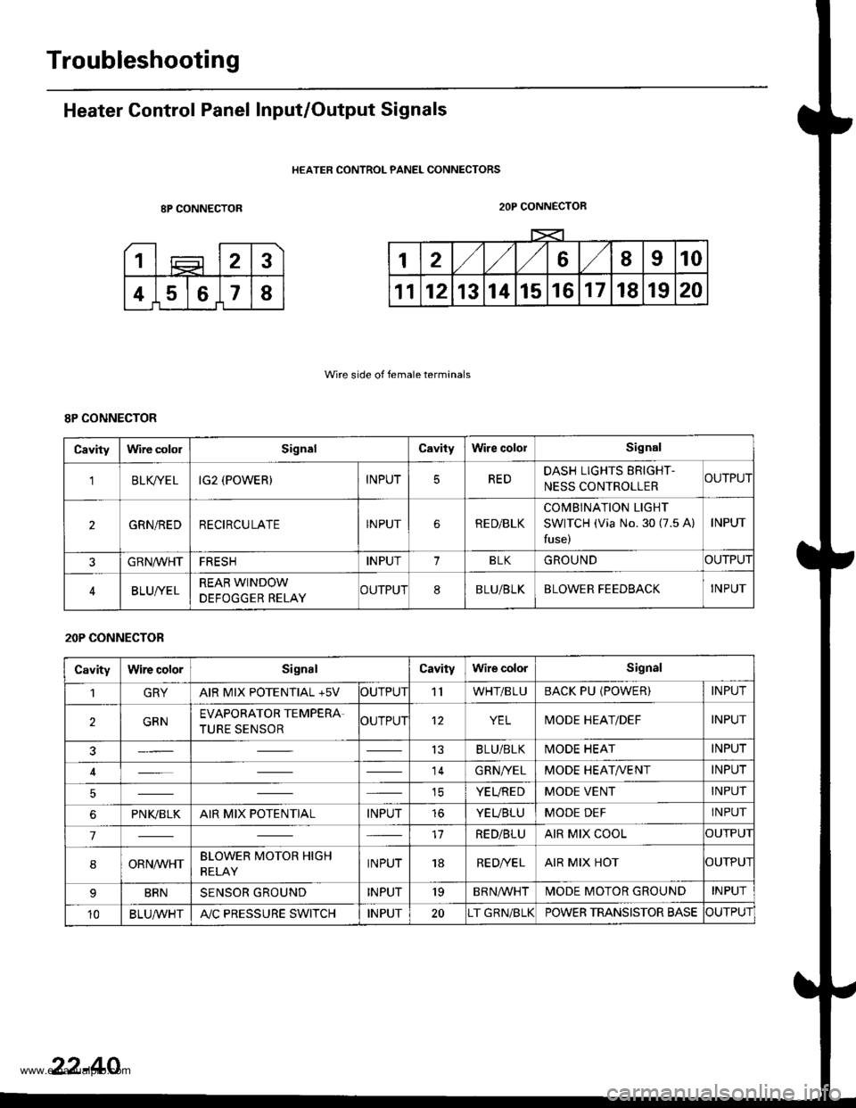
Heater Control Panel Input/Output Signals
HEATER CONTROL PANEL CONNECTORS
8P CONNECTOR
Wire side of female terminals
2OP CONNECTOR
8P CONNECTOR
Cavitylrvire cololSignalCavityWire cololSignal
'lBLK/TE LIG2 (POWER)INPUTREDDASH LIGHTS ERIGHT-
NESS CONTROLLERCUTPUT
2GRN/REDRECIRCULATEINPUTRE D/BLK
COMBINATION LIGHT
SWITCH (Via No. 30 (7.5 A)
fuse)
INPUT
GRN/VVHTFRESHINPUT1BLKGROUNDOUTPUT
BLUI/ELREAR WINDOW
DEFOGGER RELAYCUTPUT8BLU/BLKBLOWER FEEDBACKINPUT
20P CONNECTOR
CavityWire colorSignalCavityWire colorSignal
1GRYAIR MIX POTENTIAL +5VOUTPUT'llWHT/BLUBACK PU (POWER)INPUT
2GRNEVAPORATOR TEMPERA.
TURE SENSOROUTPUT12YELMODE HEAT/DEFINPUT
13BLU/BLKMODE HEATINPUT
14GRN/YELMODE HEAT/VENTINPUT
ICYEUREDMODE VENTINPUT
6PNI(BLKAIR MIX POTENTIALINPUTtoYEUBLUMODE DEFINPUT
717RED/BLUAIR MIX COOLOUTPUI
8ORNrur'HTBLOWER MOTOR HIGH
RELAYINPUT18RE D/VE LAIR MIX HOTOUTPUI
BRNSENSOR GROUNDINPUT'19BRNA/VHTIVIODE MOTOR GROUNDINPUT
10BLU,ryVHTA"/C PRESSURE SWITCHINPUT20T GRN/BLKPOWER TRANSISTOR BASECUTPUT
22-40
www.emanualpro.com
Page 1131 of 1395
Mode Control Motor
Replacement
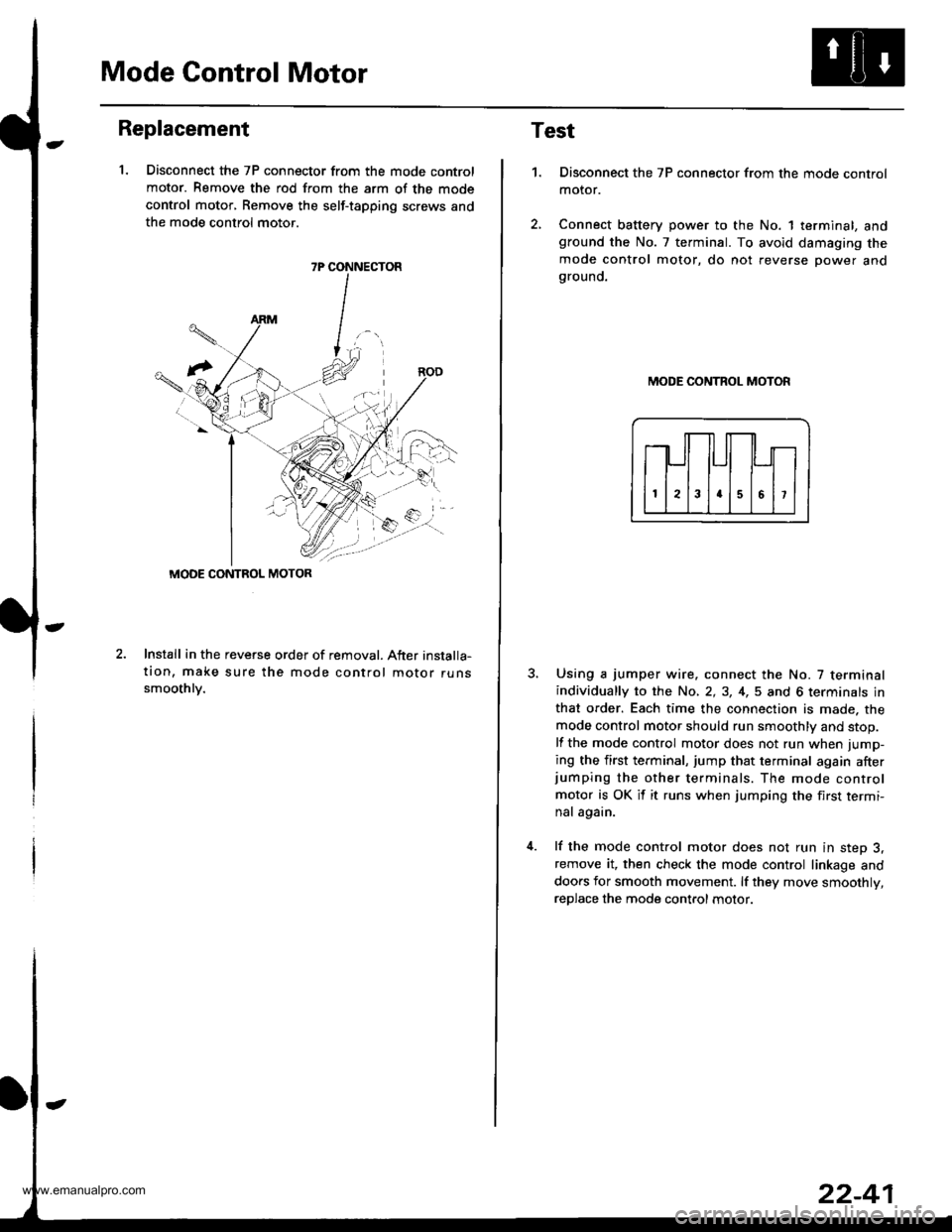
1. Disconnect the 7P connector from the mode control
motor. Remove the rod from the arm of the mode
control motor, Remove the self-tapping screws and
the mode control motor.
2.Install in the reveGe order of removal. After installa-
tion, make sure the mode control motor runssmoothlv.
7P CONNECTOR
MODE CONTROL MOTOR
Test
1.Disconnect the 7P connector from the mode control
motor.
Connect battery power to the No. 1 terminal, andground the No. 7 terminal. To avoid damaging the
mode control motor, do not reverse power andgrouno.
MODE CONTROL MOTOR
Using a jumper wire. connect the No. 7 terminalindividually to the No, 2,3, 4,5 and 6 terminals in
that order. Each time the connection is made. the
mode control motor should run smoothly and stop.
lf the mode control motor does not run when jump-
ing the first terminal, jump that terminal again afterjumping the other terminals. The mode control
motor is OK it it runs when jumping the first termi-
nal again.
lf the mode control motor does not run in step 3,remove it, then check the mode control linkage and
doors for smooth movement. lf they move smoothly,
reDlace the mode control motor.
www.emanualpro.com
Page 1132 of 1395
Recirculation Control Motor
Replacement
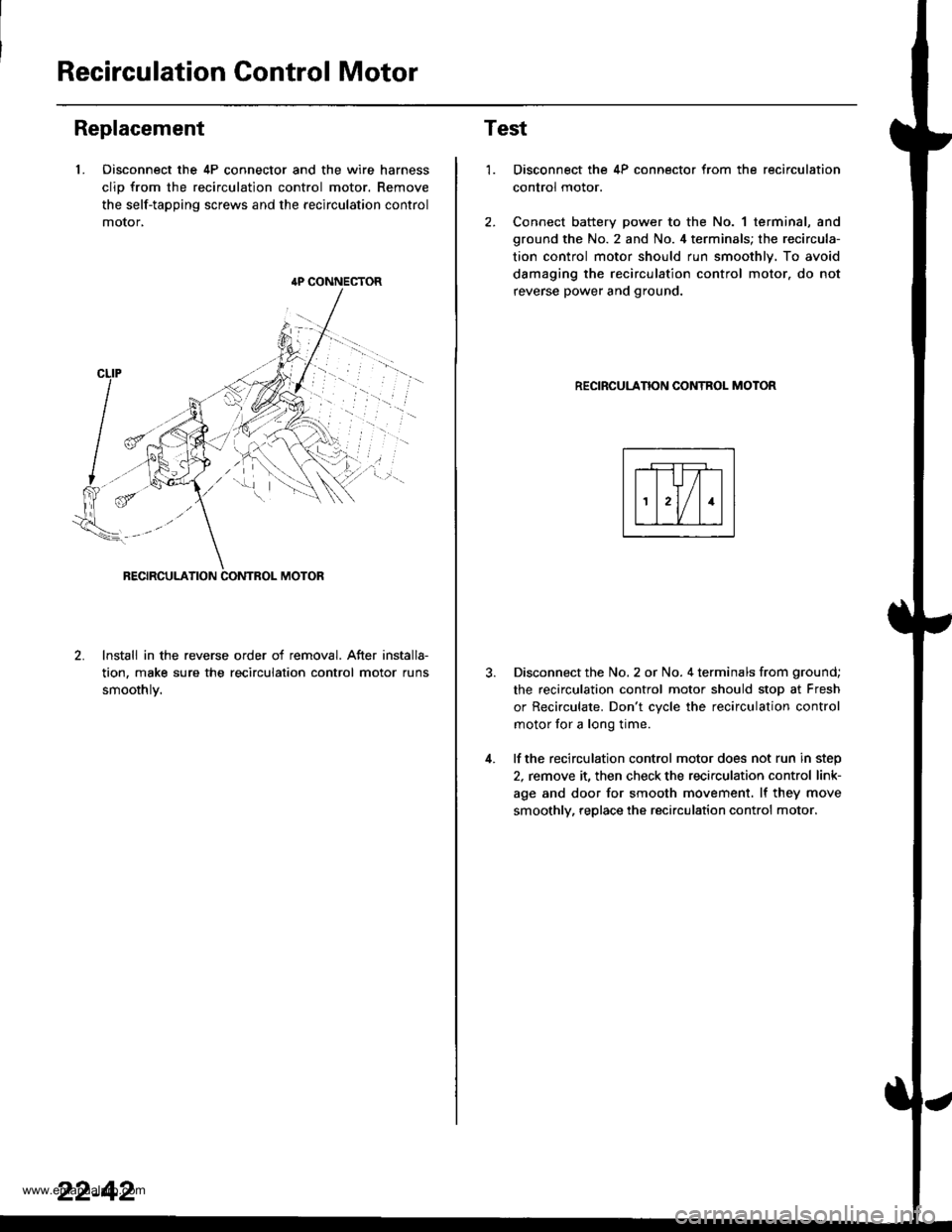
1. Oisconnect the 4P connector and the wire harness
clio from the recirculation control motor. Remove
the self-tapping screws and the recirculation control
motor,
lnstall in the reverse order of removal. After installa-
tion, make sure the recirculation control motor runs
smoothlv.
{P CONNECTOR
22-42
Test
1.
4.
Disconnect the 4P connector from the recirculation
control motor.
Connect battery power to the No. 1 terminal, and
ground the No. 2 and No. 4 terminals; the recircula-
tion control motor should run smoothly. To avoid
damaging the recirculation control motor. do not
reverse power and ground.
RECIRCULANON CONTROL MOTOR
Disconnect the No. 2 or No. 4 terminals from ground;
the recirculation control motor should stop at Fresh
or Recirculate. Don't cvcle the recirculation control
motor for a long time.
lf the recirculation control motor does not run in step
2, remove it, then check the recirculation control link-
age and door for smooth movement. lf they move
smoothly, replace the recirculation control motor.
www.emanualpro.com
Page 1133 of 1395
Air Mix Gontrol Motor
Replacement
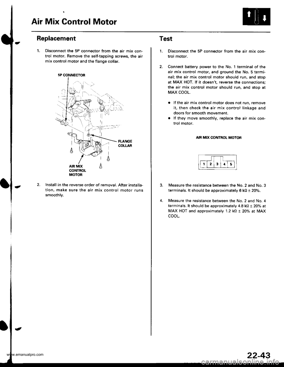
1. Disconnect the 5P connector from the air mix con-
trol motor. Remove the self-tapping screws, the air
mix control motor and the flange collar.
AIR MIXCONTROLMOTOR
A
6
Install in the reverse order of removal. After installa-
tion. make sure the air mix control motor runs
smoothlv.
5P CONNECTOR
22-43
Test
1.Disconnect the 5P connector from the air mix con-
trol motor.
Connect battery power to the No. I terminal of the
air mix control moto., and ground the No, 5 termi-
nal; the air mix control moto. should run, and stop
at MAX HOT. lf it doesn't, reverse the connections;
the air mix control motor should run, and stoo at
MAX COOL.
lf the air mix control motor does not run, remove
it, then check the air mix control linkage and
doors for smooth movement.
lf they move smoothly, replace the air mix con-
trol motor.
AIR MIX CONTROL MOTOR
4.
Measure the resistance between the No. 2 and No. 3
terminals. lt should be approximately 6 kO t 20%.
Measure the resistance between the No. 2 and No, 4
terminals, lt should be approximately 4.8 kO:t 20% at
MAX HOT and approximately '1.2 kO t 20% at lilAx
cooL.
www.emanualpro.com
Page 1134 of 1395
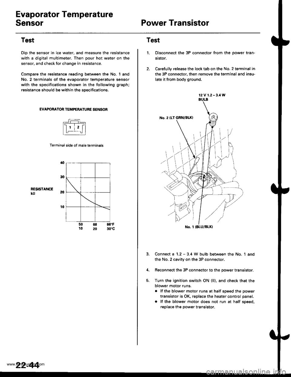
Evaporator Temperature
SensorPower Transistor
Test
Dip the sensor in ice water, and measure the resistance
with a digital multimeter. Then pour hot water on the
sensor, and check lor change in resistance.
Compare the resistance reading between the No. | 8nd
No. 2 terminals of the evaporator temperature sensor
with the specifications shown in the following graph;
resistance should be within the specifications.
EVAPOBATOR TEMPERATURE SENSOB
Terminal side ol male terminals
4
RESISTANCEko
t0
50 68 86.F10 20 30'c
22-44
12V 1.2-3.1W
No. 2 ILT GRN/BLK)
No. I IBLU/BLK)
Test
1.Disconnect the 3P connector from the oower tran-
st$or.
Carefully release the lock tab on the No. 2 terminal in
the 3P connector, then remove the terminal and insu-
late it from body ground.
Connect a 1.2 - 3.4 W bulb between the No, 1 and
the No,2 cavity on the 3P connectol
Reconnect the 3P connector to the power transistor.
Turn the ignition switch ON (ll). and check that the
blower motor runs.
a lf the blower motor runs at half soeed the oower
transistor is OK, replace the heater control panel.
. lf ths blower motor does not run at half soeed,
reDlaca the Dower transistor.
www.emanualpro.com
Page 1135 of 1395
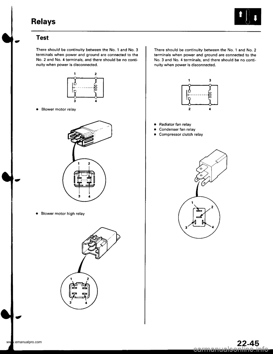
Relays
Test
There should be continuity between the No. 1 and No.3
terminals when power and ground are connected to the
No. 2 and No. 4 terminals, and there should be no conti-
nuity when power is disconnected.
3
o Blower motor relay
. Blower motor high relay
,I It)
In P
I)
There should be continuity between the No. 1 and No. 2
terminals when power and ground are connected to the
No. 3 and No. 4 terminals, and there should be no conti-
nuitv when oower is disconnected.
Rsdiator fan relay
Condenser fan relay
Compressor clutch relay
a
a
.I I
tr€
II
F)'"
,2-4.._.
22-45
www.emanualpro.com
Page 1172 of 1395
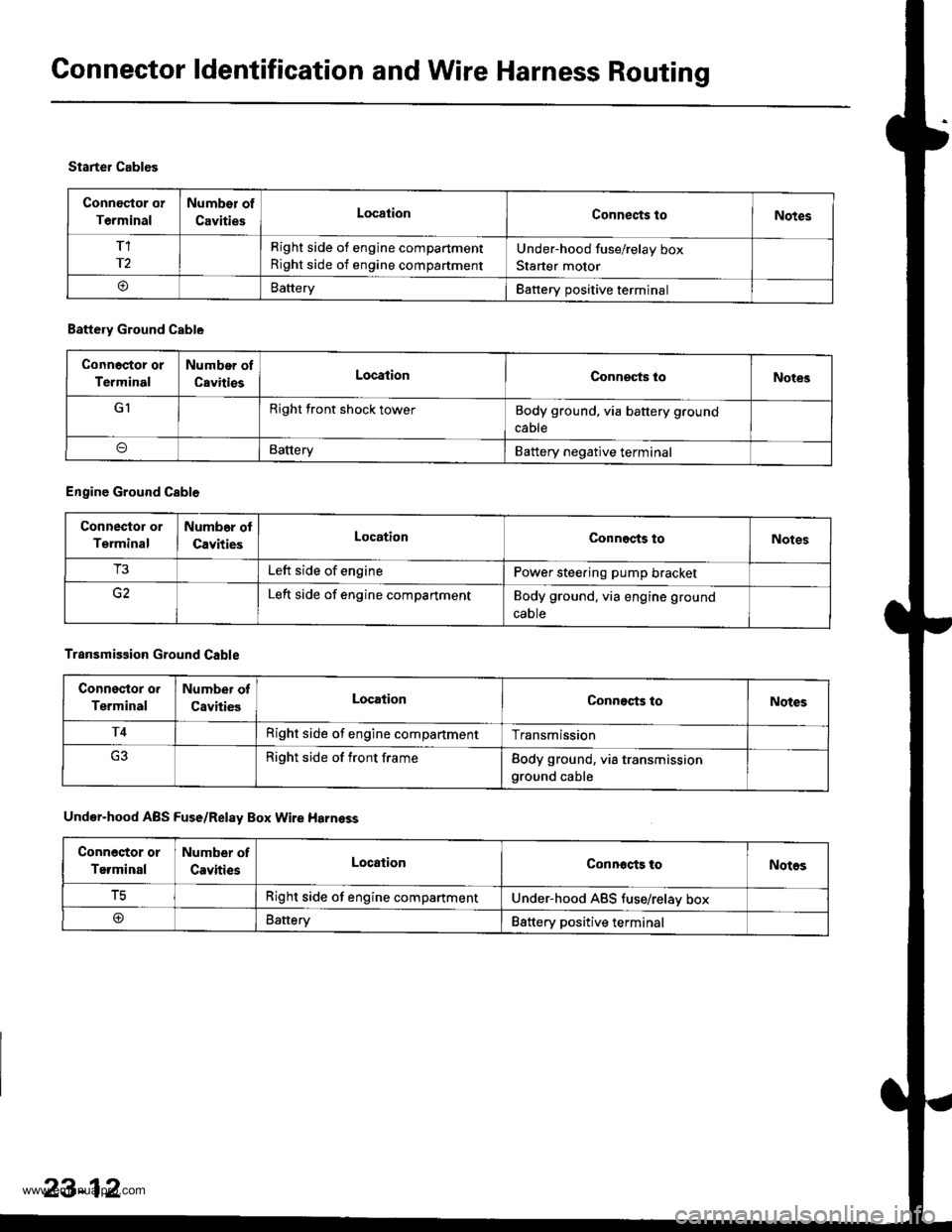
Connector ldentification and Wire Harness Routing
Connoctor or
Terminal
Number of
CavitiesLocationConnects toNotes
T1
r2
Right side of engine compartment
Right side of engine compartment
Under-hood fuse/relay box
Starter motor
oBatteryBattery positive terminal
Starter Cables
Battery Ground Cable
Connoctor or
Terminal
Number of
CavitiesLocationConneqts loNotes
GIRight front shock towerBody ground, via battery ground
cable
BatteryBattery negative terminal
Engine Ground Cable
Connector or
Terminal
Numb6r ol
CavitiesLocationConnects toNotes
T3Left side of enginePower steering pump bracket
Left side of engine compartmentBody ground. via engine ground
caote
Transmission Ground Cable
Connsstor o.
Terminal
Number of
CavitiesLocationConnects toNotes
T4Right side of engine compartmentTransmission
Right side of front frameBody ground, via transmissionground cable
Under-hood ABS Fuse/Relay Box Wire Harnsss
Conn6stor or
Terminal
Number of
CavitiesLocationConnocts toNotos
tcRight side of engine compartmentUnder-hood ABS tuse/relav box
@Battery88ttery positive terminal
23-12
www.emanualpro.com
Page 1176 of 1395
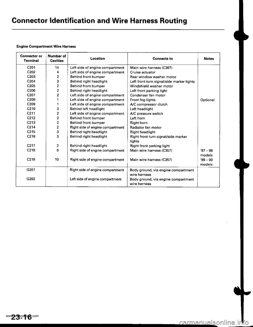
Gonnector ldentification and Wire Harness Routing
Engine Compartment Wire Harness
Connector ol
Terminal
Number of
CavitiesLocationConnects toNotes
c20'l
c202
c203
c204
c205
c206
c207
c208
c209
c210
c212
c213
c2't4
c215
c216
c217
c21A
c218
14
2
2
1'l
2
10
Left side of engine compartment
Left side of engine compartment
Behind front bumper
Behind right headlight
Behind front bumper
Behind right headlight
Left side of engine compartment
Left side of engine compartment
Left side of engine compartment
Behind left headlight
Left side of engine compartment
Behind front bumper
Behind front bumper
Right side of engine compartment
Behind right headlight
Behind right headlight
Behind right headlight
Right side of engine compartment
Right side of engine compadment
Main wire harness (C307)
Cruise actuator
Rear window washer motor
Left front turn signal/side marker lights
Windshield washer motor
Left front parking light
Condenser fan motor
Front fog lights
IVC compressor clutch
Left headlight
IVC pressure switch
Left horn
Right horn
Radiator fan motor
Right headlight
Right front turn signal/side marker
lights
Right front parking light
Main wire harness 1C357)
Main wire harness (C357)
Optional
'97 - 98
models'99 - 00
mooets
G201
G202
Right side of engine companment
Left side of engine compartment
Body ground, via engine compartment
wire harness
Body ground, via engine compartment
wire harness
23-16
www.emanualpro.com
Page 1178 of 1395
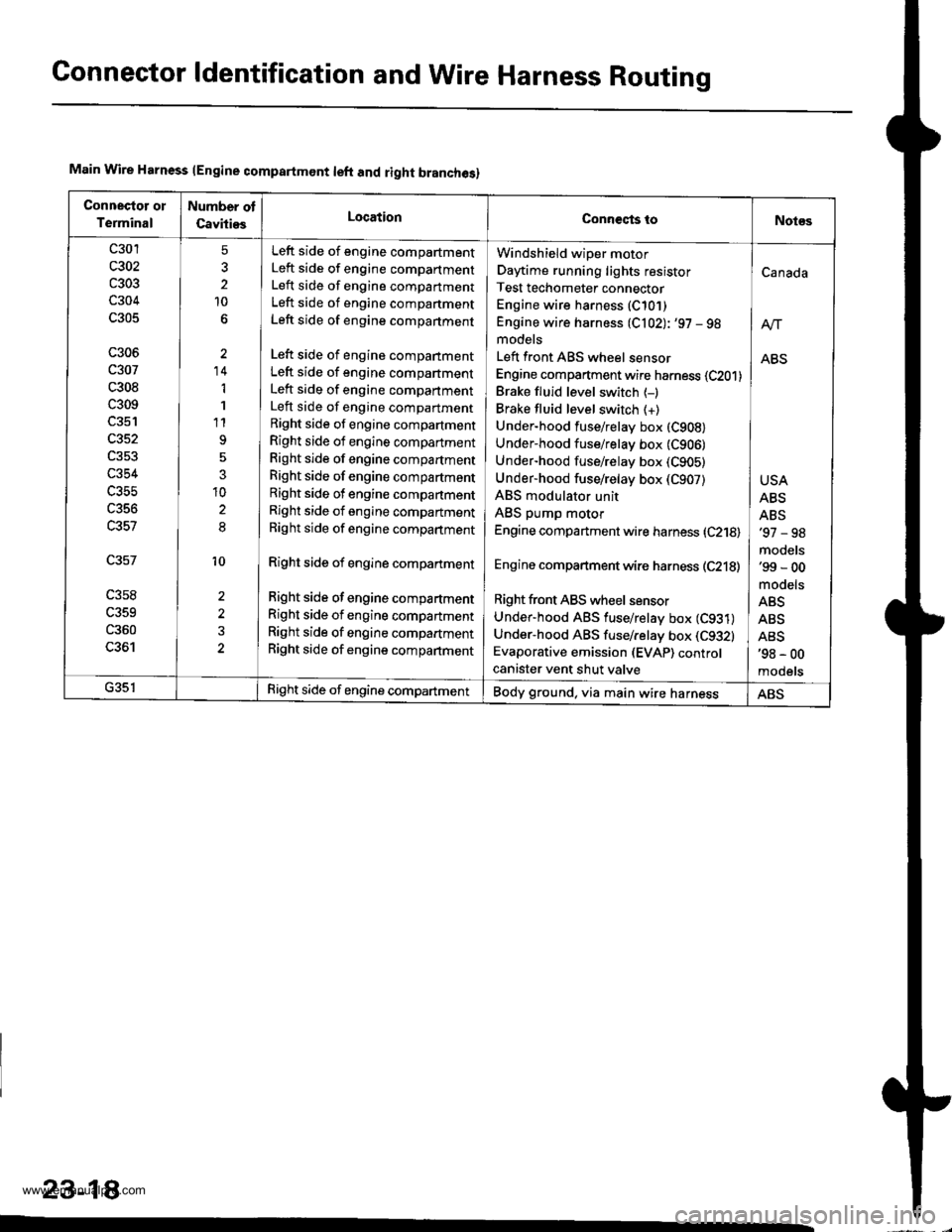
Gonnector ldentification and WireHarness Routing
Main Wire Harness lEngine compartmont left and right branches)
Connectot ol
Terminal
Number ot
CavitiesLocationConneqts toNot€s
c301
c303
c304
c305
c306
c307
c308
c309
c352
c354
c356
c357
c358
c359
c360
LJO I
5
2
10
'14
1
1
t1
3
10
8
10
2
Left side of engine compartment
Left side of engine compartment
Left side of engine compartment
Left side of engine companment
Left side of engine compartment
Left side of engine compartment
Left side of engine compartment
Left side of engine compartment
Left side of engine compartment
Right side of engine compartment
Right side of engine compartment
Right side of engine compartment
Right side of engine compartment
Right side of engine compartment
Right side of engine compartment
Right side of engine compartment
Right side of engine compartment
Right side of engine compartment
Right side of engine compartment
Right side of engine compartment
Right side of engine compartment
Windshield wiper motor
Daytime running lights resistor
Test techometer connector
Engine wire harness (C10])
Engine wire harness (C102): '97 - 98models
Left front ABS wheel sensor
Engine compartment wire harness (C201)
Brake fluid level switch {-)Brake fluid level switch (+)
Under-hood fuse/relay box (C908)
Under-hood fuse/relay box (C906)
Under-hood fuse/relay box (C905)
Under-hood fuse/relay box (C907)
ABS modulator unit
ABS pump motor
Engine compartment wire harness (C218)
Engine compartment wire harness (C218)
Right front ABS wheel sensor
Under-hood ABS fuse/retay box (C931)
Under-hood ABS fuse/relay box (C9321
Evaporative emission (EVAP) controcanister vent shut valve
Canada
ABS
USA
ABS
ABS'97 - 98
models'99 - 00
mooets
ABS
ABS
ABS'98 - 00
mooets
G35lRight side of engine compartmentBody ground, via main wire harnessABS
23-18
www.emanualpro.com