Valve spring HONDA CR-V 1997 RD1-RD3 / 1.G Owner's Manual
[x] Cancel search | Manufacturer: HONDA, Model Year: 1997, Model line: CR-V, Model: HONDA CR-V 1997 RD1-RD3 / 1.GPages: 1395, PDF Size: 35.62 MB
Page 671 of 1395
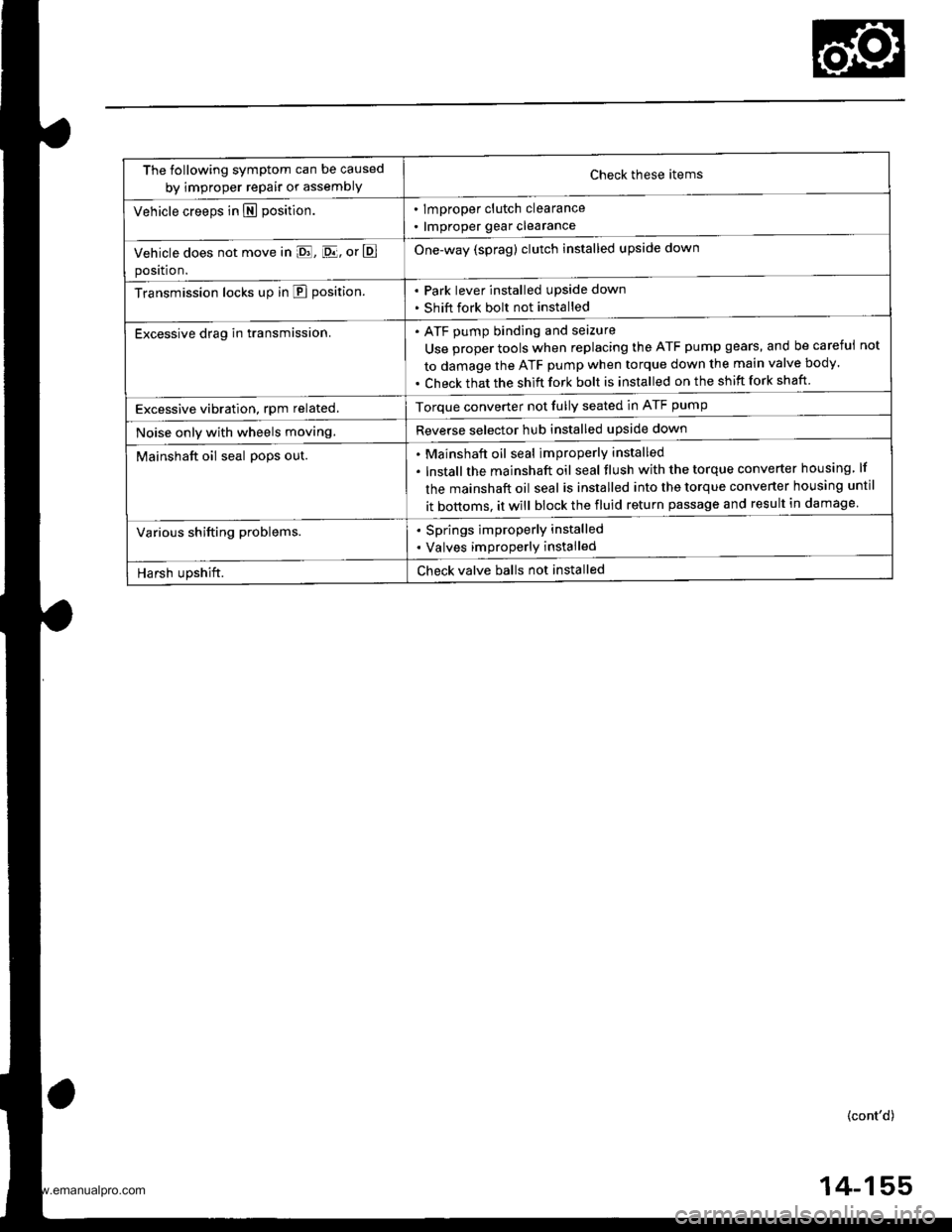
The following symptom can be caused
by improper repair or assemblYCheck these items
. lmproper clutch clearance
. lmproper gear clearance
One-way (sprag) clutch installed upside down
Park lever installed upside down
Shift fork bolt not installed
Vehicle creeps in N position.
Vehicle does not move in E, [D.lj, or E
position.
Transmission locks up in E position.
Excessive drag in transmission.ATF pump binding and seizure
Use proper tools when replacing the ATF pump gears, and be careful
to damage the ATF pump when torque down the main valve body.
Check that the shift fork bolt is installed on the shift fork shaft
not
Excessive vibration, rpm related.Torque converter not fully seated in ATF pump
Reverse selector hub installed upside downNoise only with wheels moving.
Mainshaft oil seal po9s out.Mainshaft oil seal improperly installed
lnstallthe mainshaft oil seal tlush with the torque converter housing lf
the mainshaft oil seal is installed into the torque converter housing until
it bottoms. it will block the fluid return passage and result in damage
Various shifting problems.. Springs improperly installed
. Valves improperly installed
Harsh upshift.Check valve balls not installed
(cont'd)
4-155
www.emanualpro.com
Page 695 of 1395
oa;\,6
G)!o,
a@,6
@o(a
@(}
@a@@@@@@@6@@)@@@@@@@@@@@@@
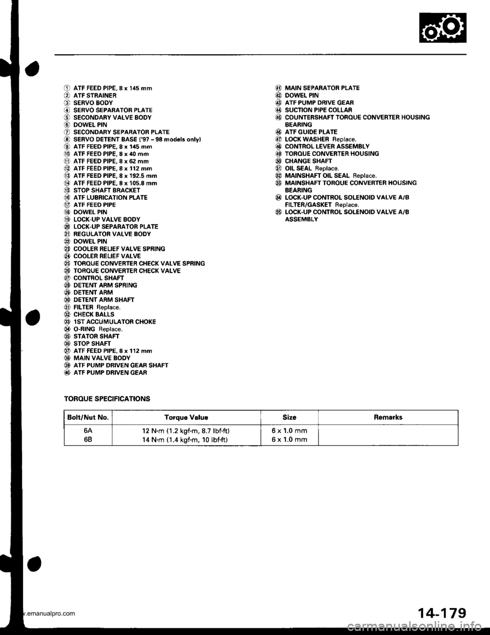
ATF FEED PIPE,8 x 145 mmATF STRAINERSERVO BODYSERVO SEPARATOR PLATESECONDARY VALVE EODYDOWEL PINSECONDARY SEPARATOR PLATESERVO DETENT BASE ('97 - 98 model3 onlylATF FEED PIP€, 8 x 145 mmATF FEED PIPE,8 x 40 mmATF FEED PIPE. 8 x 62 mmATF FEED PIPE.8 x 112 mmATF FEED PIPE, 8 x 192.5 mmATF FEEO PIPE. I x 105.8 mmSTOP SHAFT BRACKETATF LUBRICATION PLATEATF FEEO PIPEDOWEL PINLOCK-UP VALVE EODYLOCK-UP SEPARATOR PLATEREGULATOR VALVE BODYDOWEL PINCOOLER RELIEF VALVE SPRINGCOOLER RELIEF VALVETOROUE CONVERTER CHECK VALVE SPRINGTOROUE CONVERTER CHECK VALVECONTROL SHAFTOETENT ARM SPRINGOETENT ARMDETENT ARM SHAFTFILTER Replace.CHECK BALLSlST ACCUMULATOR CHOKEO"RING Replace.STATOR SHAFTSTOP SHAFTATF FEED PIPE, I x 112 mmMAIN VALVE BOOYATF PUMP DRIVEN GEAR SHAFTATF PUMP DRIVEN GEAR
TOROUE SPECIFICATIONS
MAIN SEPARATOR PLATEDOWEL PINATF PUMP DRIVE GEARSUCTION PIPE COLLARCOUNTERSHAFT TOROUE CONVERTER HOUSINGBEARINGATF GUIDE PLATELOCK WASHER Replace.CONTROL LEVER ASSEMBLYTOROUE CONVERTER HOUSINGCHANGE SHAFTOIL SEAL Reolace.MAINSHAFT OIL SEAL Reolace.MAINSHAFT TOROUE CONVERT€R HOUSINGBEARINGLOCK.UP CONTROL SOLENOID VALVE A/BFILTER/GASKET Replace.LOCK.UP CONTROL SOLENOID VALVE A/BASSEMBLY
@@@@@
@@@@@@@@
@
@
Bolt/Nut No.Torque ValugSizeRomarks
64
6B
12 N'm (1.2 kgf.m,8.7 lbf.ft)
14 N.m (1.4 kgf.m, 10 lbf.ft)
6x1.0mm
6x1.0mm
14-179
www.emanualpro.com
Page 701 of 1395
![HONDA CR-V 1997 RD1-RD3 / 1.G Owners Manual
ai_la2,
(41/4.:4.
\7)
1.0)tl
(3]
t9.1q
oo,ID@,8!Itt\,29
€4
69
aa.21
600toa
04
6!)ent00t.@
ATF FEED PIPE, I x 145 mm
ATF STRAINERSERVO BODYSERVO SEPARATOB PLATESECONDABY VALVE BOOYDOWEL PINSECONDAR HONDA CR-V 1997 RD1-RD3 / 1.G Owners Manual
ai_la2,
(41/4.:4.
\7)
1.0)tl
(3]
t9.1q
oo,ID@,8!Itt\,29
€4
69
aa.21
600toa
04
6!)ent00t.@
ATF FEED PIPE, I x 145 mm
ATF STRAINERSERVO BODYSERVO SEPARATOB PLATESECONDABY VALVE BOOYDOWEL PINSECONDAR](/img/13/5778/w960_5778-700.png)
ai_la2',
(41/4.:4.
\7)
1.0)tl
(3]
t9.1q
oo,ID@,8!Itt\,29
€4
69
aa.21
600toa
04
6!)ent00t.@
ATF FEED PIPE, I x 145 mm
ATF STRAINERSERVO BODYSERVO SEPARATOB PLATESECONDABY VALVE BOOYDOWEL PINSECONDARY SEPARATOR PLATE
SERVO DETENT BASE ('98 model onlvl
ATF FEED PIPE, 8 x 145 mmATF FEED PIPE.8 x 40 mmATF FEED PIPE,8 x 62 mmATF FEED PIPE, I x 112 mm
ATF FEED PIPE, 8 x 192.5 mm
ATF FEED PIPE, 8 x 105.8 mm
STOP SHAFT BRACKETATF LUERICATION PLATEATF FEED PIPEDOWEL PINLOCK-UP VALVE BODYLOCK-UP SEPARATOR PLATE
REGULATOR VALVE BOOYDOWEL PINCOOLER RELIEF VALVE SPRINGCOOLER BELIEF VALVETOROUE CONVERTER CHECK VALVE SPRING
TOROUE CONVERTER CHECK VALVECONTNOL SHAFTDETENT ARM SPRINGDETENT ARMDETENT ARM SHAFTFILTER Replace.CHECK BALLS1ST ACCUMULATOR CHOKEO-RING Replace.STATOR SHAFTSTOP SHAFTATF FEED PIPE. 8 x 112 mmMAIN VALVE BODYATF PUMP DRIVEN GEAR SHAFTATF PUMP DRIVEN GEAR
MAIN SEPARATOR PLATE
DOWEL PINATF PUMP DRIVE GEARSUCTION PIPE COLLARCOUNTEBSHAFT TOROUE CONVERTER HOUSING
BEARINGATF GUIDE PLATEATF MAGNETTOBOUE CONVERTER HOUSINGOIL SEAL Beplace.MAINSHAFT OIL SEAL Replace.MAINSHAFT TOROUE CONVERTER HOUSING
BEARINGLOCK.UP CONTROL SOLENOID VALVE A/B
FILTER/GASKET Replace.LOCK-UP CONTROL SOLENOID VALVE A/B
ASSEMELY
i4ll(4d
@@.!!l
art)@@@@li]t
TOROUE SPECIFICATIONS
Bolt/Nut No.Torque ValueSizeRemarks
12 N.m (1.2 kgim,8.7 lbf'tt)6x1.0mm
14-185
www.emanualpro.com
Page 707 of 1395
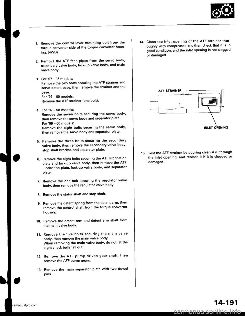
1.Remove the control lever mounting bolt trom the
torque converter side of the torque converter hous-
ing. (4WD)
Remove the ATF feed pipes from the servo body,
secondary valve body, lock-up valve body, and main
valve body.
For '97 - 98 models:
Remove the two bolts securing the ATF strainer and
servo detent base, then remove the strainer and the
base.
For'99 - 00 models;
Remove the ATF strainer {one bolt).
4. For'97 - 98 models:
Remove the seven bolts securing the servo body,
then remove the servo body and separator plate'
For'99 - 00 models:
Remove the eight bolts securing the servo body,
then remove the servo body and separator plate'
5. Bemove the three bolts securing the secondary
valve body, then remove the secondary valve body'
stop shaft bracket, and separator plate.
6. Remove the eight bolts securing the ATF lubrication
plate and lock-up valve body, then remove the ATF
lubrication plate, lock-up valve body' and separator
plate.
7. Remove the one bolt securing the regulator valve
body, then remove the regulator valve body'
8. Remove the stator shaft and stop shaft.
9. Remove the detent spring from the detent arm, then
remove the control shaft from the torque converter
houslng.
10. Remove the detent arm and detent arm shaft from
the main valve body.
11. Remove the five bolts securing the main valve
body, then remove the main valve body.
When removing the main valve body, do not let the
eight check balls fall out.
12. Remove the ATF pump driven gear shaft, then
remove the ATF PumP gears.
13. Remove the main separator plate with two dowel
prns.
14, Clean the inlet opening of the ATF strainer thor-
oughly with compressed air, then check that it is in
good condition, and the inlet opening is not clogged
or damaged.
15.
INLET OPENING
Test the ATF strainer by pouring clean ATF through
the inlet opening, and replace it if it is clogged or
damaged.
14-191
www.emanualpro.com
Page 709 of 1395
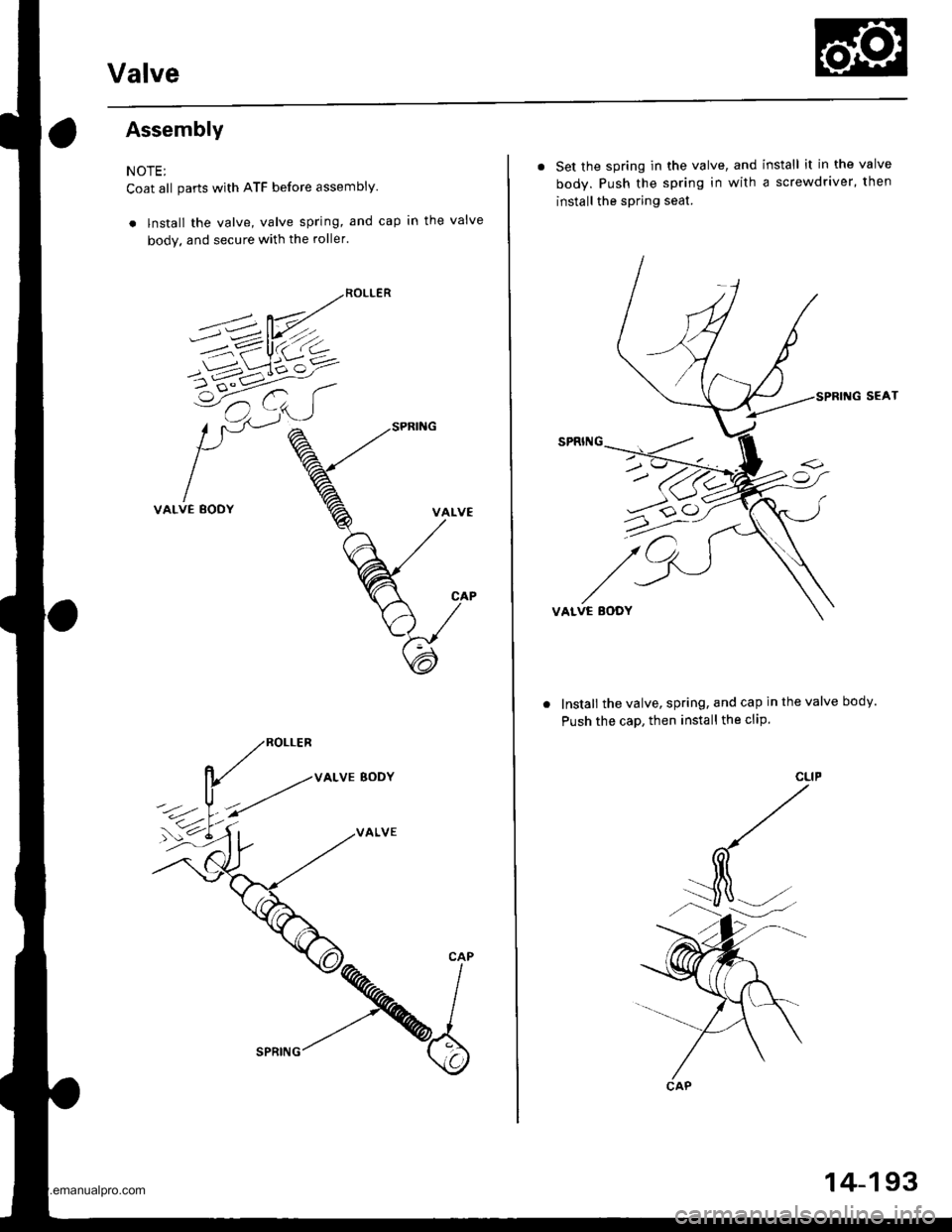
Valve
Assembly
NOTE;
Coat all parts with ATF before assembly.
. lnstall the valve, valve spring, and cap in the valve
body. and secure with the roller.
VALVE BODY
VALVE
. Set the spring in the valve, and install it in the valve
body. Push the spring in with a screwdriver, then
install the spring seat.
SEAT
VALVE EODY
Install the valve, spring, and cap in the valve body.
Push the caD, then install the cliP.
u>o
CAP
14-193
www.emanualpro.com
Page 710 of 1395
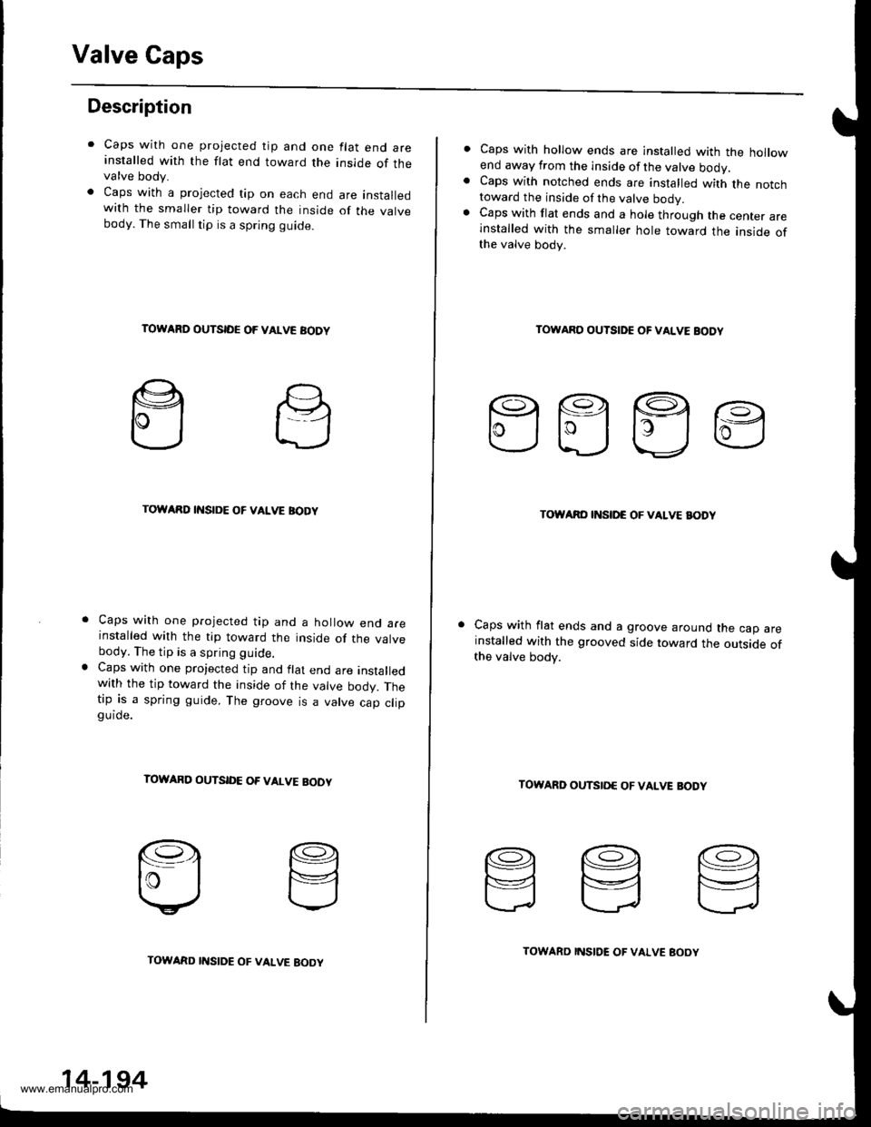
Valve Gaps
Description
Caps with one projected tip and one flat end areinstalled with the flat end toward the inside of thevalve body.
Caps with a projected tip on each end are installedwith the smaller tip toward the inside of the valvebody. The small tip is a spring guide.
TOWARD OUTSIDE OF VALVE AODY
TOWARD INSIDE OF VALVE BODY
Caps with one projected tip and a hollow end areinstalled with the tip toward the inside of the valvebody. The tip is a spring guide.
Caps with one projected tip and flat end are installedwith the tip toward the inside of the valve bodv. Thetip is a spring guide. The groove is a valve cao cliogu ide.
TOWARD OUTSID€ OF VALVE BOOY
14-194
TOWARD I'{SIDE OF VALVE EOOYTOWARD INSIDE OF VALVE BOOY
Caps with hollow ends are installed with the hollowend away from the inside of the valve ooov.Caps with notched ends are installed with the notchtoward the inside of the valve bodv.Caps with flat ends and a hole through the center areinstalled with the smaller hole toward the inside ofthe valve body.
TOWARO OUTSIDE OF VALVE BODY
EEEE
TOWARO INSII'C OF VALVE BODY
Caps with flat ends and a groove around the cap areinstalled with the grooved side toward the outside ofthe valve body.
TOWARD OUTSIO€ OF VAIVE BODY
www.emanualpro.com
Page 712 of 1395
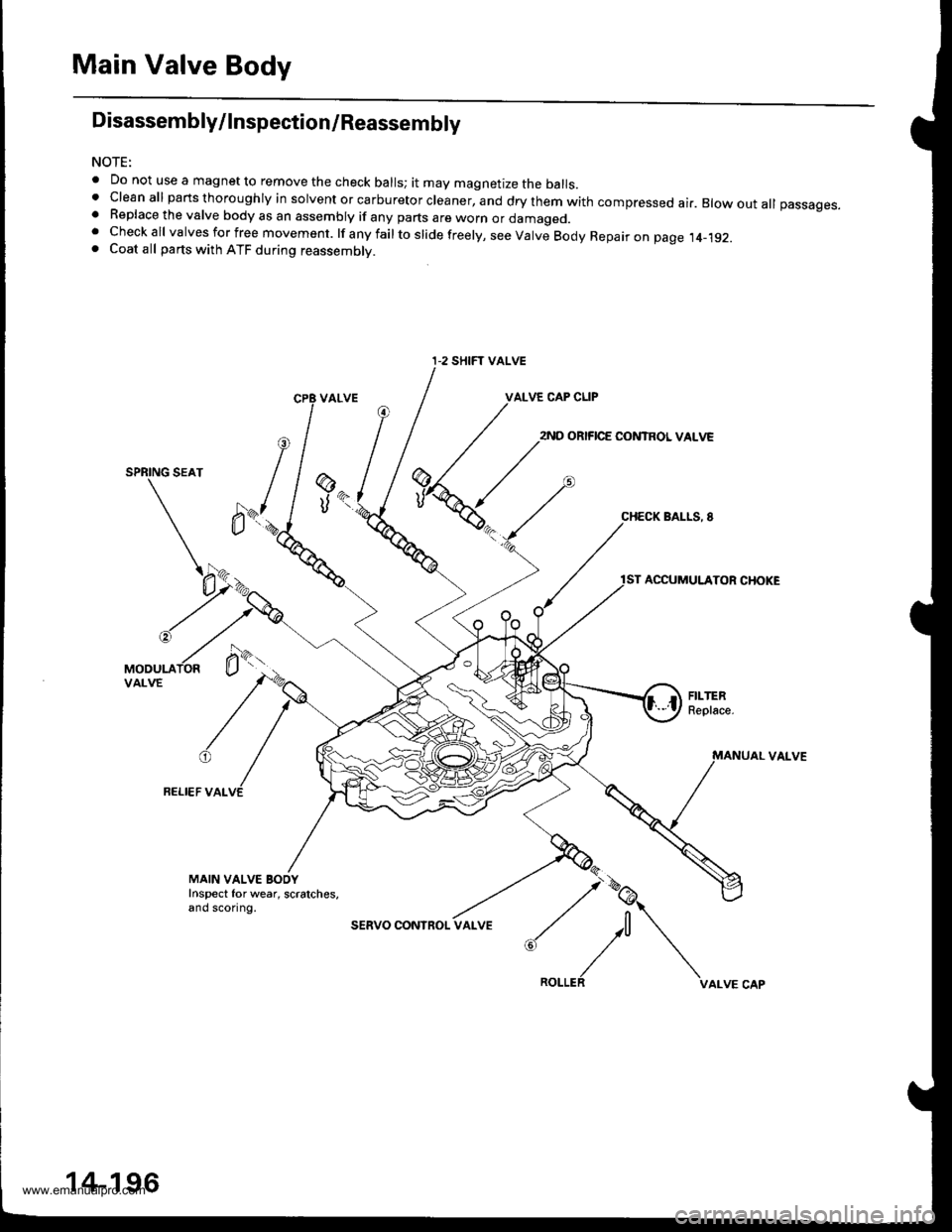
Main Valve Body
Disassembly/lnspection/Reassembly
NOTE:
. Do not use a magnet to remove the check balls; it may magnetize the balls.t clean all parts thoroughly in solvent or carburetor cleaner, and dry them with compressed ai.. Blow out all passages.. Replace the valve body as an assembly if any parts are worn or damageo.. Checkall valvesforfree movement. lfanyfailtoslidefreely,seeValveBodyRepaironpage.t4_192.. Coat all parts with ATF during reassembly.
VALVE CAP CLIP
2ND ORIFICE CONTROL VALVE
SPRING SEAT
BALLS, 8
ACCUMULATOR CHOKE
VAI-VE
FELI€F VALVE
@
UK
MAIN VALVE BOOYInspect for wear, scratches,and sconng.
sERVO CONInOL
:,/\^._.^,
I-2 SHIFT VALVE
14-196
www.emanualpro.com
Page 713 of 1395
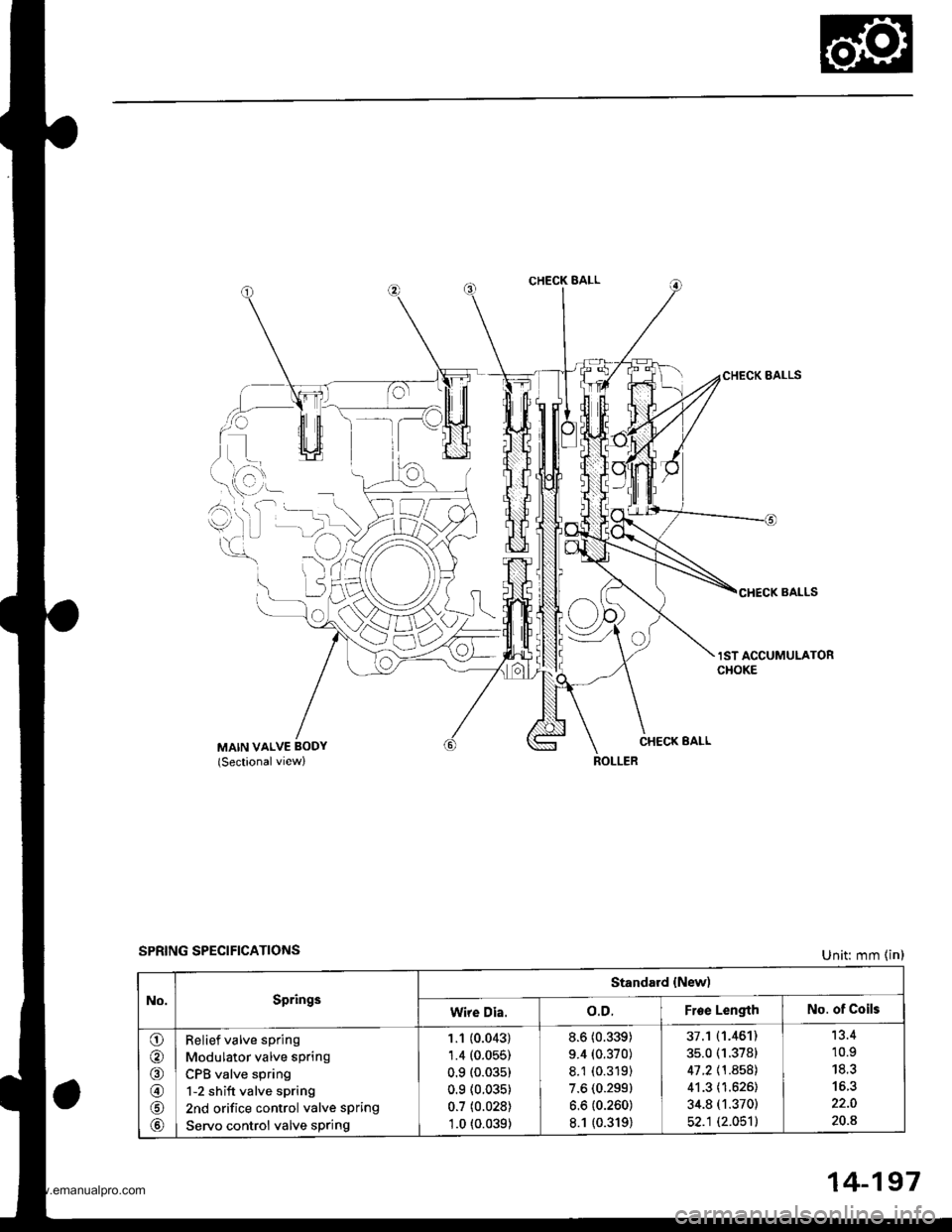
CHECK BALL
i)L)
lo
CHECK BALLS
lST ACCUMULATORCHOKE
CHECK EALLMAIN VALVE BODY(Sectionalview)
SPRING SPECIFICATIONSUnit: mm (in)
No.Springs
Standard {New)
Wire Dia.o.D.Froe LengthNo. of Coils
o
@
@
@
Relief valve spring
Modulator valve spring
CPB valve spring
1-2 shift valve spring
2nd orifice control valve spring
Servo control valve sPring
1.1 (0.043)
1.4 (0.055)
0.9 (0.03s)
0.9 (0.035)
0.7 (0.028)
1.0 t0.039)
8.6 (0.339)
9.4 (0.370)
8.1 (0.319)
7.6 (0.299)
6.6 (0.260)
8.1 {0.319)
37.1 (1.461)
35.0 (1.3781
41 .2 \1 .8581
41.3 (1.626)
34.8 (1.370)
52.1 (2.051)
'13.4
10.9
20.8
14-197
www.emanualpro.com
Page 714 of 1395
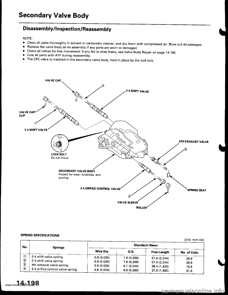
Secondary Valve Body
Disassembly/lnspection/Reassembly
NOTE:
' clean all parts thoroughly in solvent or carburetor cleaner. and dry them with compressed air. Blow out aU passages,. Replace the valve body as an assembly if any parts are worn or damaged.t check all valves for free movement. rf anyfair to sride freery. see varve Body Repair on page 14-192.. Coat all parts with ATF during reassembly.. The CPC valve is installed in the secondary valve body, held in place by the lock bolt.
@,.-.t'tr.,
,rr'^'//u
"/ ./
3-' SHIFT VALVE
VALVE CAP
SPRING SPEC!FICATIONS
2.3 SHIFT VALVE
VALVE SLEEVE
ROLLER
ilTH EXHAUST VALVE
N"*,"o"*,
Unit: mm (in)
t*-1
SECONOARY VALVE BODYInspect for wear, scratches, andscorang.
3.4 ORIFICE CONTROL VAL
No.SpringsStandald {Nswl
Wire Dia.o.D.Free LengthNo. of Coils
o
@
o
@
3 4 shift valve spring
2-3 shift valve spring
4th exhaust valve spring
3-4 orifice control valve spring
0.9 (0.035)
0.9 (0.035)
0.9 {0.035)
0.6 {0.024}
7.6 (0.299)
7.6 (0.299)
6.1 (0.240t
6.6 (0.2601
57 .O i.2.2441
57 .O 12.244J
36.4 (1.433)
37.9 (1.492)
26.A
26.8
19.5
31.6
14-198
www.emanualpro.com
Page 715 of 1395
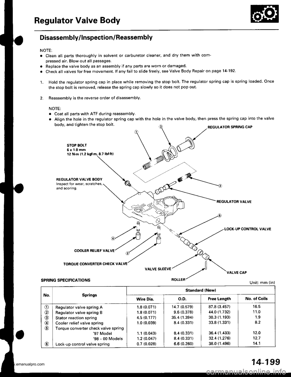
Regulator Valve Body
Disassembly/lnspection/Reassembly
NOTE:
o Clean all parts thoroughly in solvent or carburetor cleaner, and dry them with com-
pressed air. Blow out all passages.
. Replace the valve body as an assembly if any parts are worn or damaged.
. Checkall valvesforfree movement. lf anyfail toslidefreely, see Valve Body Repair on page l4-192.
'1. Hold the regulator spring cap in place while removing the stop bolt. The regulator spring cap is spring loaded Once
the stop bolt is removed, release the spring cap slowly so it does not pop out.
2. Reassembly is the reverse order of disassembly.
NOTE:
. Coat all parts with ATF during reassembly.
. Align the hole in the regulator spring cap with the hole in the valve body, thenpress the spring cap into the valve
REGULATOR SPSING CAPbody, and tighten the stop bolt.
STOP BOLT6x1.0mm12 N.m 11.28.? tbt.fil
REGULATOR VALVE BODYlnspect for wear, scratches,ano scoflng.
REGULATOR VALVE
No,SpringsStandard {New}
wire Dia.o.D.F ee LengthNo. ot Coils
o
@
@,6
a,
Regulator valve spring A
Regulator valve spring B
Stator reaction spring
Cooler relief valve spring
Torque converter check valve spring'97 Model'98 - 00 Models
Lock-up control valve spring
1.8 (0.071)
1.8 (0.071)
4.5 (0.177)
1.0 {0.039)
1.1 (0.043)
1.2lO.O47l
0.7 t0.028)
14.7 (0.579)
9.6 (0.378)
35.4 (1.394)
8.4 {0.331)
8.4 (0.331)
8.4 (0.331)
6.6 (0.260)
87.8 (3.457)
44.0 t1.7321
30.3 (1.193)
33.8 (1.331)
36.4 (1.433)
32.4 11.2761
38.0 (1.496)
'11.0
1.9
't2.0
12.7
14.'l
14-199
www.emanualpro.com