gears HONDA CR-V 1997 RD1-RD3 / 1.G Owner's Manual
[x] Cancel search | Manufacturer: HONDA, Model Year: 1997, Model line: CR-V, Model: HONDA CR-V 1997 RD1-RD3 / 1.GPages: 1395, PDF Size: 35.62 MB
Page 671 of 1395
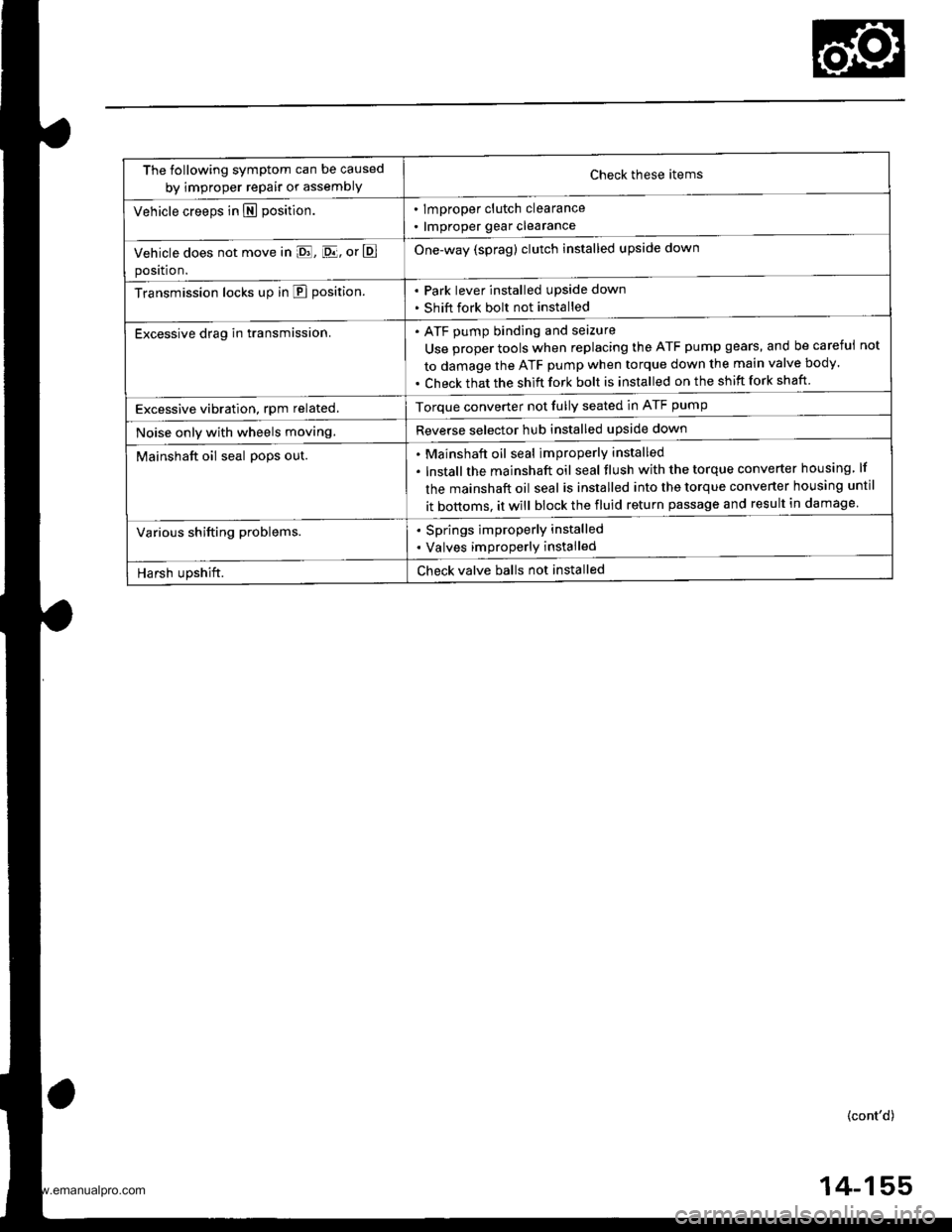
The following symptom can be caused
by improper repair or assemblYCheck these items
. lmproper clutch clearance
. lmproper gear clearance
One-way (sprag) clutch installed upside down
Park lever installed upside down
Shift fork bolt not installed
Vehicle creeps in N position.
Vehicle does not move in E, [D.lj, or E
position.
Transmission locks up in E position.
Excessive drag in transmission.ATF pump binding and seizure
Use proper tools when replacing the ATF pump gears, and be careful
to damage the ATF pump when torque down the main valve body.
Check that the shift fork bolt is installed on the shift fork shaft
not
Excessive vibration, rpm related.Torque converter not fully seated in ATF pump
Reverse selector hub installed upside downNoise only with wheels moving.
Mainshaft oil seal po9s out.Mainshaft oil seal improperly installed
lnstallthe mainshaft oil seal tlush with the torque converter housing lf
the mainshaft oil seal is installed into the torque converter housing until
it bottoms. it will block the fluid return passage and result in damage
Various shifting problems.. Springs improperly installed
. Valves improperly installed
Harsh upshift.Check valve balls not installed
(cont'd)
4-155
www.emanualpro.com
Page 672 of 1395

Symptom-to-Com ponent Chart
Hydraulic System (cont'd)
NOTES
See flushing procedure, page l4-264 and 265,
BSet idle rpm in gear to specified idle speed. lf still no good, adjust motor mounts as outlined in enginesection of this manual.
clf the large clutch piston O-ring is broken, inspect the piston groove for rough machining.
Dlf the clutch pack is seized or is excessively worn. inspect the other clutches fot wear, and check the orificecontrol valves, CPC valve, and linear solenoid for free movement.
lf the linear solenoid is stuck, inspect the clutches for wear.
lf the 1-2 shift valve is stuck closed. the transmission will not upshift. lf stuck open, the transmission hasno lst gear.
Hlf the 2nd orifice control valve is stuck, inspect the 2nd and 3rd clutch Dacks for wear.
lf the 3-4 orifice control valve is stuck, inspect the 3rd and 4th clutch packs for wear.
Jlf the clutch pressure control valve is stuck closed. the transmission will not shift out of lst gear.
Klmproper alignment of main valve body and torque converter housing may cause ATF pump seizure. Thesymptoms are mostly an rpm-related ticking noise or a high-pitched squeak.
Llf the ATF strainer is clogged with particles of steel or aluminum, inspect the ATF pump and differentialpinion shaft. lf both are OK and no cause for the contamination is found, replace the torque converter.
Mlf the lst clutch feed pipe guide in the end cover is scored by the mainshaft. inspect the ball bearing forexcessive movement in the transmission housing. lf oK, replace the end cover as it is dented. The o-rinounder the guide is probably worn.
N' Replace the mainshaft if the bushing for the 4th feed pipe is loose or damaged, lf the 4th feed pipe is darrFaged or out of round. replace the end cover.' Replace the mainshaft if the bushing for the l st feed pipe is loose or damaged. lf the 1st feed pipe is dam-aged or out of round, replace it.
oA worn or damaged sprag clutch is mostly a result of shifting the transmission in E!. E, or E positionwhile the wheels rotate in reverse. such as rocking the vehicle in snow.
PInspect the frame for collision damage.
lnspect for damage and wear:
l. Reverse selector gear teeth chamfers.
2. Engagement teeth chamfers of countershaft 4th and reverse gear.
3. Shift fork for scuff marks in center.
4. Differential pinion shaft for wear under pinion gears.
5. Bottom of 3rd clutch for swirl marks.
Replace items 1, 2, 3. and 4 if worn or damaged. lf transmission makes a clicking, grinding, or whirring noise,also replace mainshaft 4th gear, reverse idler gear, and countershaft 4th gear in addition to 1,2, 3, or 4.lf differential pinion shaft is worn, overhaul differential assembly, replace ATF strainer, and thoroughly cjeantransmission, flush torque converter. cooler, and lines,lf bottom of 3rd clutch is swirled and transmission makes gear noise. replace the countershaft and final drivenoear,
Be very careful not to damage the torque converter housing when replacing the main ball bearing. you
may also damage the ATF pump when you torque down the main valve body. This will result in ATF pumpseizure if not detected. Use the Drooer tools.
SInstall the main seal flush with the torque converter housing. lf you push it into the torque converterhousing until it bottoms out, it will block the fluid return passage and result in damage.
www.emanualpro.com
Page 695 of 1395
oa;\,6
G)!o,
a@,6
@o(a
@(}
@a@@@@@@@6@@)@@@@@@@@@@@@@
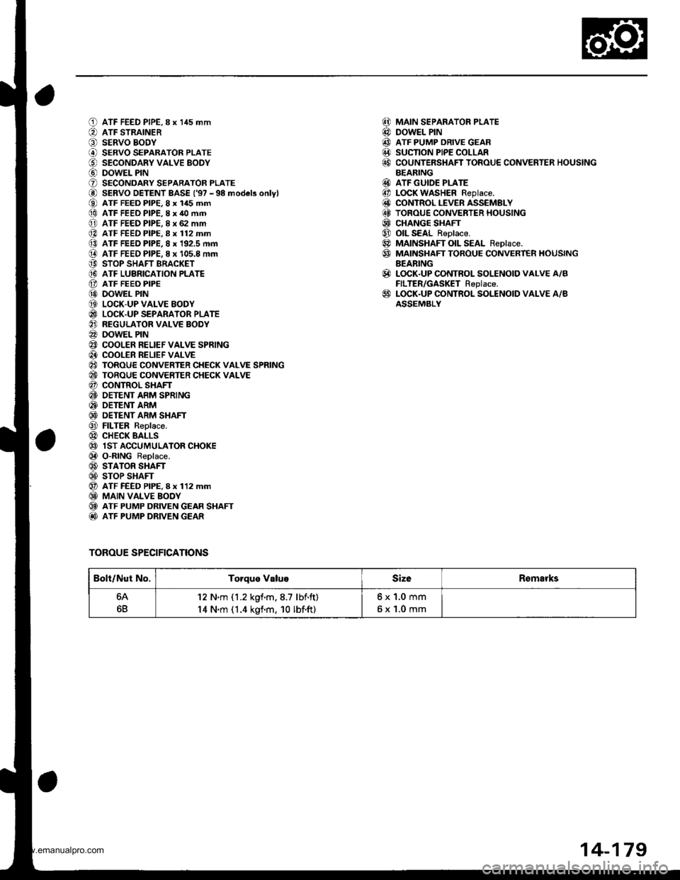
ATF FEED PIPE,8 x 145 mmATF STRAINERSERVO BODYSERVO SEPARATOR PLATESECONDARY VALVE EODYDOWEL PINSECONDARY SEPARATOR PLATESERVO DETENT BASE ('97 - 98 model3 onlylATF FEED PIP€, 8 x 145 mmATF FEED PIPE,8 x 40 mmATF FEED PIPE. 8 x 62 mmATF FEED PIPE.8 x 112 mmATF FEED PIPE, 8 x 192.5 mmATF FEEO PIPE. I x 105.8 mmSTOP SHAFT BRACKETATF LUBRICATION PLATEATF FEEO PIPEDOWEL PINLOCK-UP VALVE EODYLOCK-UP SEPARATOR PLATEREGULATOR VALVE BODYDOWEL PINCOOLER RELIEF VALVE SPRINGCOOLER RELIEF VALVETOROUE CONVERTER CHECK VALVE SPRINGTOROUE CONVERTER CHECK VALVECONTROL SHAFTOETENT ARM SPRINGOETENT ARMDETENT ARM SHAFTFILTER Replace.CHECK BALLSlST ACCUMULATOR CHOKEO"RING Replace.STATOR SHAFTSTOP SHAFTATF FEED PIPE, I x 112 mmMAIN VALVE BOOYATF PUMP DRIVEN GEAR SHAFTATF PUMP DRIVEN GEAR
TOROUE SPECIFICATIONS
MAIN SEPARATOR PLATEDOWEL PINATF PUMP DRIVE GEARSUCTION PIPE COLLARCOUNTERSHAFT TOROUE CONVERTER HOUSINGBEARINGATF GUIDE PLATELOCK WASHER Replace.CONTROL LEVER ASSEMBLYTOROUE CONVERTER HOUSINGCHANGE SHAFTOIL SEAL Reolace.MAINSHAFT OIL SEAL Reolace.MAINSHAFT TOROUE CONVERT€R HOUSINGBEARINGLOCK.UP CONTROL SOLENOID VALVE A/BFILTER/GASKET Replace.LOCK.UP CONTROL SOLENOID VALVE A/BASSEMBLY
@@@@@
@@@@@@@@
@
@
Bolt/Nut No.Torque ValugSizeRomarks
64
6B
12 N'm (1.2 kgf.m,8.7 lbf.ft)
14 N.m (1.4 kgf.m, 10 lbf.ft)
6x1.0mm
6x1.0mm
14-179
www.emanualpro.com
Page 701 of 1395
![HONDA CR-V 1997 RD1-RD3 / 1.G Owners Manual
ai_la2,
(41/4.:4.
\7)
1.0)tl
(3]
t9.1q
oo,ID@,8!Itt\,29
€4
69
aa.21
600toa
04
6!)ent00t.@
ATF FEED PIPE, I x 145 mm
ATF STRAINERSERVO BODYSERVO SEPARATOB PLATESECONDABY VALVE BOOYDOWEL PINSECONDAR HONDA CR-V 1997 RD1-RD3 / 1.G Owners Manual
ai_la2,
(41/4.:4.
\7)
1.0)tl
(3]
t9.1q
oo,ID@,8!Itt\,29
€4
69
aa.21
600toa
04
6!)ent00t.@
ATF FEED PIPE, I x 145 mm
ATF STRAINERSERVO BODYSERVO SEPARATOB PLATESECONDABY VALVE BOOYDOWEL PINSECONDAR](/img/13/5778/w960_5778-700.png)
ai_la2',
(41/4.:4.
\7)
1.0)tl
(3]
t9.1q
oo,ID@,8!Itt\,29
€4
69
aa.21
600toa
04
6!)ent00t.@
ATF FEED PIPE, I x 145 mm
ATF STRAINERSERVO BODYSERVO SEPARATOB PLATESECONDABY VALVE BOOYDOWEL PINSECONDARY SEPARATOR PLATE
SERVO DETENT BASE ('98 model onlvl
ATF FEED PIPE, 8 x 145 mmATF FEED PIPE.8 x 40 mmATF FEED PIPE,8 x 62 mmATF FEED PIPE, I x 112 mm
ATF FEED PIPE, 8 x 192.5 mm
ATF FEED PIPE, 8 x 105.8 mm
STOP SHAFT BRACKETATF LUERICATION PLATEATF FEED PIPEDOWEL PINLOCK-UP VALVE BODYLOCK-UP SEPARATOR PLATE
REGULATOR VALVE BOOYDOWEL PINCOOLER RELIEF VALVE SPRINGCOOLER BELIEF VALVETOROUE CONVERTER CHECK VALVE SPRING
TOROUE CONVERTER CHECK VALVECONTNOL SHAFTDETENT ARM SPRINGDETENT ARMDETENT ARM SHAFTFILTER Replace.CHECK BALLS1ST ACCUMULATOR CHOKEO-RING Replace.STATOR SHAFTSTOP SHAFTATF FEED PIPE. 8 x 112 mmMAIN VALVE BODYATF PUMP DRIVEN GEAR SHAFTATF PUMP DRIVEN GEAR
MAIN SEPARATOR PLATE
DOWEL PINATF PUMP DRIVE GEARSUCTION PIPE COLLARCOUNTEBSHAFT TOROUE CONVERTER HOUSING
BEARINGATF GUIDE PLATEATF MAGNETTOBOUE CONVERTER HOUSINGOIL SEAL Beplace.MAINSHAFT OIL SEAL Replace.MAINSHAFT TOROUE CONVERTER HOUSING
BEARINGLOCK.UP CONTROL SOLENOID VALVE A/B
FILTER/GASKET Replace.LOCK-UP CONTROL SOLENOID VALVE A/B
ASSEMELY
i4ll(4d
@@.!!l
art)@@@@li]t
TOROUE SPECIFICATIONS
Bolt/Nut No.Torque ValueSizeRemarks
12 N.m (1.2 kgim,8.7 lbf'tt)6x1.0mm
14-185
www.emanualpro.com
Page 707 of 1395
1.Remove the control lever mounting bolt trom the
torque converter side of the torque converter hous-
ing. (4WD)
Remove the ATF feed pipes from the servo body,
secondary valve body, lock-up valve body, and main
valve body.
For '97 - 98 models:
Remove the two bolts securing the ATF strainer and
servo detent base, then remove the strainer and the
base.
For'99 - 00 models;
Remove the ATF strainer {one bolt).
4. For'97 - 98 models:
Remove the seven bolts securing the servo body,
then remove the servo body and separator plate'
For'99 - 00 models:
Remove the eight bolts securing the servo body,
then remove the servo body and separator plate'
5. Bemove the three bolts securing the secondary
valve body, then remove the secondary valve body'
stop shaft bracket, and separator plate.
6. Remove the eight bolts securing the ATF lubrication
plate and lock-up valve body, then remove the ATF
lubrication plate, lock-up valve body' and separator
plate.
7. Remove the one bolt securing the regulator valve
body, then remove the regulator valve body'
8. Remove the stator shaft and stop shaft.
9. Remove the detent spring from the detent arm, then
remove the control shaft from the torque converter
houslng.
10. Remove the detent arm and detent arm shaft from
the main valve body.
11. Remove the five bolts securing the main valve
body, then remove the main valve body.
When removing the main valve body, do not let the
eight check balls fall out.
12. Remove the ATF pump driven gear shaft, then
remove the ATF PumP gears.
13. Remove the main separator plate with two dowel
prns.
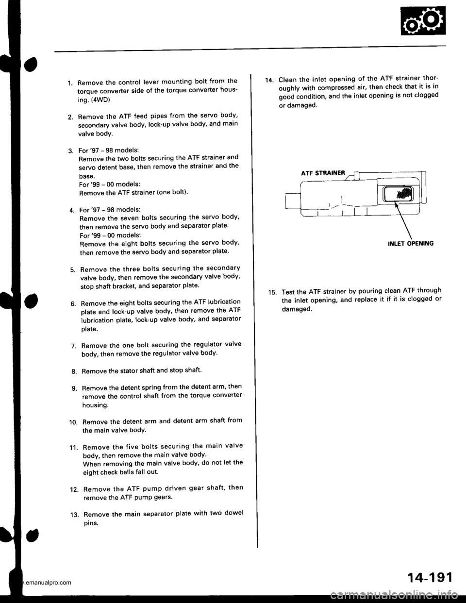
14, Clean the inlet opening of the ATF strainer thor-
oughly with compressed air, then check that it is in
good condition, and the inlet opening is not clogged
or damaged.
15.
INLET OPENING
Test the ATF strainer by pouring clean ATF through
the inlet opening, and replace it if it is clogged or
damaged.
14-191
www.emanualpro.com
Page 711 of 1395
ATF Pump
Inspection
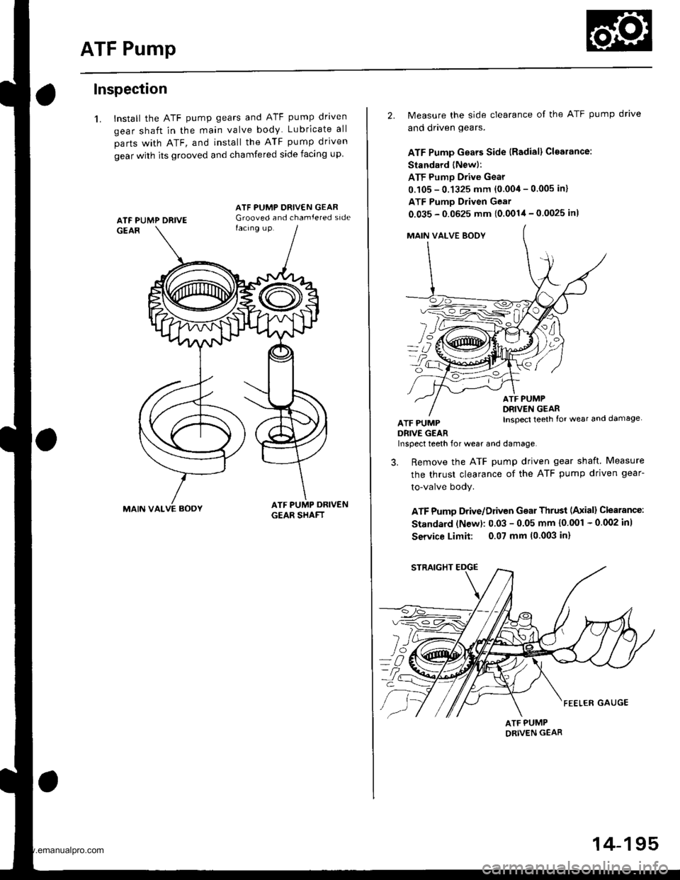
1. Install the ATF pump gears and ATF pump driven
gear shaft in the main valve body Lubricate all
parts with ATF, and install the ATF pump driven
gear with its grooved and chamfered side facing up
MAIN VALVE AOOY
ATF PUMP ORIVE
2. Measure the side clearance of the ATF pump drive
and driven gears.
ATF Pump Gears Side {Radial} Cloarance:
Standard (Newl:
ATF Pump Drive Gear
0.105 - 0.1325 mm {0.004 - 0.005 in}
ATF Pumo Driven Gear
0.035 - 0.0625 mm {0.0014 - 0.0025 in)
MAIN VAI-VE BOOY
fl
L/
ATF PUMPDRIVE GEAR
ATF PUMPDRIVEN GEARInspecl teeth {or wear and damage
Inspect teeth for wear and damage,
3. Remove the ATF pump driven gear shaft Measure
the thrust clearance of the ATF pump driven gear-
to-valve body.
ATF Pumo Drive/Driven Gear Thrust (Axiall Clearance:
Standard (N€w): 0.03 - 0.05 mm {0'001 - 0 002 inl
Service Limit: 0.07 mm 10.003 in)
ATF PUMPORIVEN GEAR
14-195
www.emanualpro.com
Page 739 of 1395
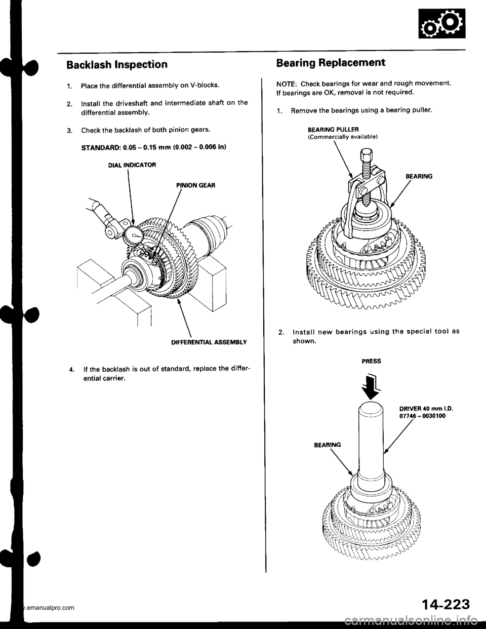
Backlash Inspection
Place the differential assembly on V-blocks.
lnstall the driveshaft and intermediate shaft on the
differential assemblY.
Check the backlash of both pinion gears.
STANDARD: 0.05 - 0.15 mm (0.002 - 0.006 in)
OIFFEBENNAL ASSEMBLY
It the backlash is out of standard, replace the difter-
ential carrier.
1.
DIAL INDICATOR
Bearing Replacement
NOTE: Check bearings for wear and rough movement.
lf bearings are OK, removal is not required.
1. Remove the bearings using a bearing puller.
BEARING PULLER(Commercially available)
lnstall new
snown.
bearings using the sPecial tool
PRESS
14-223
www.emanualpro.com
Page 767 of 1395
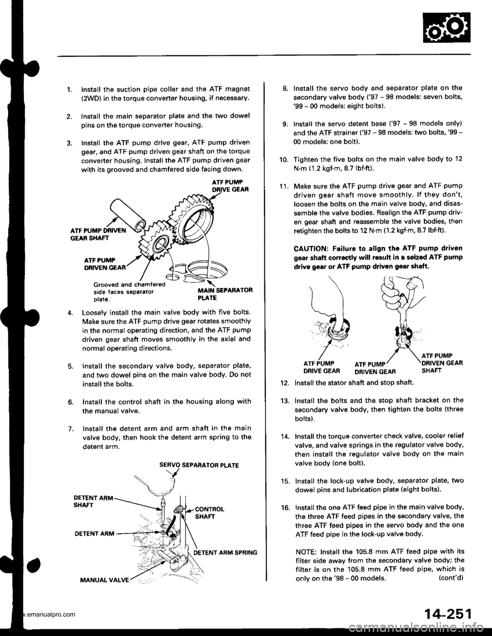
1.Install the suction pipe collar and the ATF magnet
{2WD) in the torque converter housing, if necessary.
lnstall the main seDarator Dlate and the two dowel
pins on the torque converter housing,
Install the ATF pump drive gear. ATF pump driven
gear, and ATF pump driven gear shaft on the torque
converter housing. Installthe ATF pump driven gear
with its grooved and chamfered side facing down.
ATF PUMPGEAR
ATF PUMP D{IVEf{GEAR SHAFT
ATF PUi'PORIVEN GEAR
Grooved and chamteredside faces separatorplate.
MAIN S€PAR/ATORPLATE
5.
o.
Loosely install the main valve body with five bolts.
Make sure the ATF pump drive gear rotates smoothly
in the normal operating direction, and the ATF pump
driven gear shaft moves smoothly in the axial and
normal operating directions.
Install the secondary valve body, separator plate,
and two dowel pins on the main valve body. Do not
installthe bolts.
Install the control shaft in the housing along with
the manual valve.
lnstall the detent arm and arm shaft in the main
valve body, then hook the detent arm spring to the
detent arm.
SEBVO SEPARATOR PLATE
7.
DETENT ARMSHAFT
OETENT ARM
CONTROLSHAFT
MANUAL VAIVE
OETENT ARM SPRING
onlv on the '98 - 00 models,
14-251
1l.
9.
8.
10.
Install the servo body and separator plate on the
secondary valve body ('97 - 98 models: seven bolts,'99 - 00 models: eight bolts).
lnstall the servo detent base ('97 - 98 models only)
and the ATF strainer ('97 - 98 models: two bolts,'99 -
00 models: one boltl.
Tighten the five bolts on the main valve body to 12
N'm (1.2 kgf.m, 8.7 lbf.ft).
Make sure the ATF pump drive gear and ATF pump
driven gear shaft move smoothly. lf they don't,
loosen the bolts on the main valve body, and disas-
semble the valve bodies. Realign the ATF pump driv-
en gear shaft and reassemble the valve bodies, then
retighten the bolts to 12 N.m (1.2 kgim, 8.7 lbf.ft).
CAUTION: Failure to align the ATF pump driven
gear shaft corroctly will rosult in a seizsd ATF pump
drive gear or ATF pump drivon gear shaft.
ATF PUMP ATFGEARDRIVE GEAR DBIVEN GEARSHAFT
Install the stator shaft and stop shaft
Install the bolts and the stop shaft bracket on the
secondary valve body, then tighten the bolts (three
bolts).
Install the torque converter check valve, cooler relief
valve, and valve springs in the regulator valve body,
then install the regulator valve body on the main
valve body {one boltl.
Install the lock-up valve body, separator plate, two
dowel pins and lubrication plate (eight bolts).
Installthe one ATF feed pipe in the main valve body,
the three ATF feed pipes in the secondary valve, the
three ATF feed pipes in the servo body and the one
ATF feed pipe in the lock-up valve body.
NOTE: lnstall the 105.8 mm ATF feed pipe with its
filter side away from the secondary valve body; the
filter is on the 105.8 mm ATF feed pipe, which is(cont'd)
13.
14.
15.
16.
www.emanualpro.com
Page 779 of 1395

26. Connect the vehicle speed sensor (VSS). the coun-
tershaft speed sensor. and the A,/T gear position
switch connectors,
VEHICLE SPEEO
SPEED SENSOACO'{NECTOR
Connect the lock-up control solenoid valve connec-
tor, then install the harness clamp on the clamp
bracket.
HARNESS CI-AMP
27.
RADIATOR HOSECLAMP
TRANSMISSIONGROUND CAB1ITERMINAL
LOCK-UP OONTROLSOLENOID VALVECONNECTOR
6x1.0mm12 N'm (1.2 kgi.m,8.? tbtftl
28.
29.
Instail the transmission ground cable terminal on
the transmission hanger, and install the radiator
hose clamp on the transmission hanger,
Connect the starter cables to the starter, and install
the harness clamD on the clamD bracket. Make sure
the crimped side of the starter cable ring terminal is
facing out.
STARTEBCABLE
STARTER CAAtf,
Install the air cleaner housing assembly and the
intake air duct.
Refill the transmission with ATF (see page 14-161).
Connect the battery positive terminal and negative
terminal.
Set the parking brake, Start the engine, and shift the
transmission through all gears three times.
Check the shift cable adjustment (see page 14-271]-.
Check the tront wheel alignment and adjust it if
needed (see section 18).
Let the engine reach normal operating temperature
(the radiator fan comes on) with the transmission in
E or N position, then turn it off and check the ATF
level {see page 14-160).
Perform a road test (see page 14-157 and 14-158).
30.
31.
34.
CLAMP BRACKET
37.
14-263
www.emanualpro.com
Page 788 of 1395
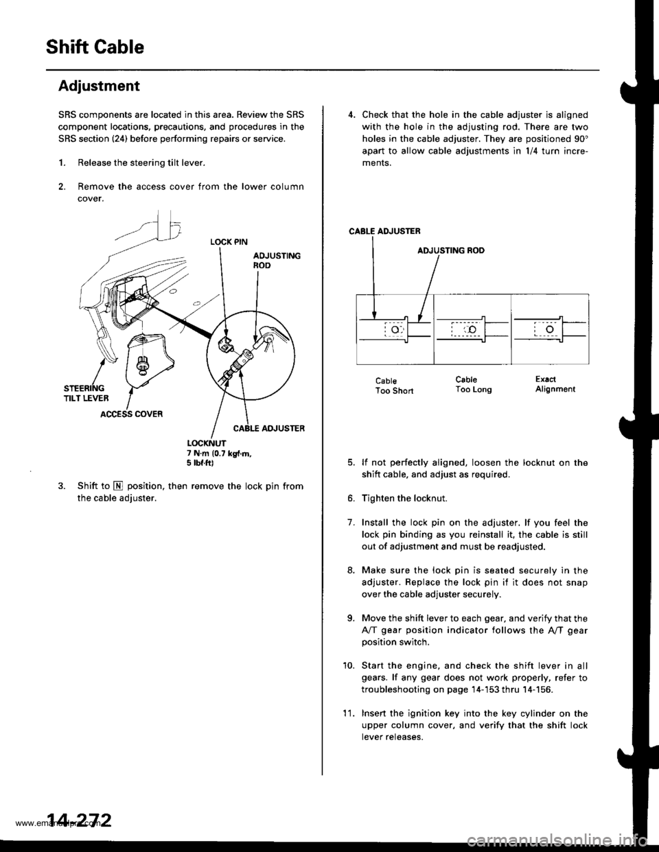
Shift Gable
Adjustment
SRS components are located in this area. Review the SRS
component locations, precautions, and procedures in the
SRS section (241 before performing repairs or service.
1. Release the steering tilt lever.
2. Remove the access cover from the lower column
cover.
LOCK PIN
AOJUSTINGnoo
ADJUSTER
7 N.m (0.7 kg{.m,5 tbf.ft)
3. Shift to E position. then remove the lock pin from
the cable adjuster.
K\ffi
/* 1 6-,>
snenrftc YTILT LEVER IACCESS COVER
14-272
'l 1.
4. Check that the hole in the cable adjuster is aligned
with the hole in the adjusting rod. There are two
holes in the cable adjuster. They are positioned 90"
apart to allow cable adjustments ln l/4 turn incre-
ments.
CABLE ADJUSTER
CablsToo Short
lf not perfectly aligned, loosen the locknut on the
shitt cable. and adjust as required.
Tighten the locknut.
Install the lock pin on the adjuster. lf you feel the
lock pin binding as you reinstall it, the cable is still
out of adjustment and must be readjusted.
Make sure the lock pin is seated securely in the
adjuster. Replace the lock pin if it does not snap
over the cable adjuster securely.
Move the shift lever to each gear, and verify that the
A/T gear position indicator follows the A"/T gear
position switch.
Start the engine, and check the shift lever in all
gears. lf any gear does not work properly, refer to
troubleshooting on page 14-'153 thru 14-156.
Insert the ignition key into the key cylinder on the
upper column cover, and verify that the shift lock
tever reteases.
CableToo LongExactAlignment
7.
a
10.
www.emanualpro.com