head bolt HONDA CR-V 1997 RD1-RD3 / 1.G Owner's Manual
[x] Cancel search | Manufacturer: HONDA, Model Year: 1997, Model line: CR-V, Model: HONDA CR-V 1997 RD1-RD3 / 1.GPages: 1395, PDF Size: 35.62 MB
Page 769 of 1395
17.
18.
19.
20.
21.
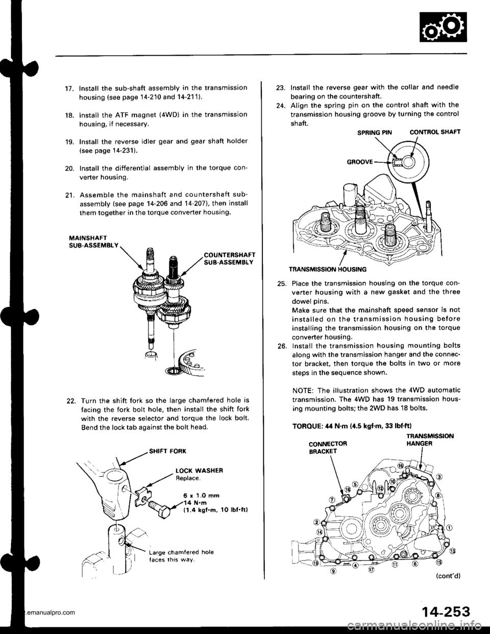
Install the sub-shaft assembly in the transmission
housing (see page 14-210 and 14-2'111.
lnstall the ATF magnet (4WD) in the transmission
housing, if necessary.
Install the reverse idler gear and gear shaft holder
(see page 14-231).
Install the differential assembly in the torque con-
verter housing.
Assemble the mainshaft and countershaft sub-
assembly (see page 14-206 and 14 207],, then install
them together in the torque converter houslng.
COUNTERSHAFTSUB-ASSEMBLY
Turn the shift fork so the large chamfered hole is
facing the fork bolt hole. then install the shift fork
with the reverse selector and torque the lock bolt.
Bend the lock tab against the bolt head.
SHIFI FORK
LOCK WASHERBeplace.
6 r 'l.O mm4 N.m(1.4 ksl.m. 1O lbt.ft)
Large chamfered hole
24.
Install the reverse gear with the collar and needle
bearing on the countershatt.
Align the spring pin on the control shaft with the
transmission housing groove by turning the control
shaft.
SPRING PIN CONTROL SHAFT
TRANSMISSION HOUSING
25. Place the transmission housing on the torque con-
verter housing with a new gasket and the three
dowel pins,
Make sure that the mainshaft speed sensor is not
installed on the transmission housing before
installing the transmission housing on the torque
converter housing.
26. Install the transmission housing mounting bolts
along with the transmission hanger and the connec-
tor bracket, then torque the bolts in two or more
steos in the seouence shown.
NOTE: The illustration shows the 4WD automatic
transmission. The 4WD has 19 transmission hous-
ing mounting bolts; the 2WD has 18 bolts.
TOROUE: 44 N.m {,[.5 kgf.m, 33 lbf'ft)
{cont'd)
14-253
SPRING PIN
TNANSMISSION
www.emanualpro.com
Page 863 of 1395
Steering Wheel
Removal
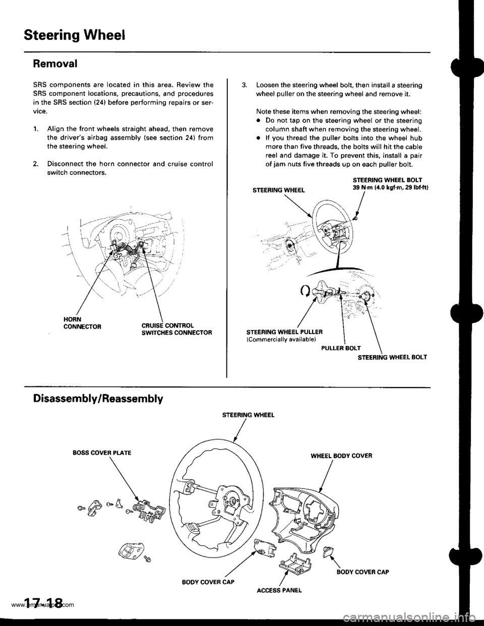
SRS components are located in this area. Review the
SRS component locations, precautions, and procedures
in the SRS section (24) before performing repairs or ser-
vice.
1. Align the front wheels straight ahead. then remove
the driver's airbag assembly (see section 24) from
the steering wheel.
2. Disconnect the horn connector and cruise control
switch connectors.
CONTROLSWITCHES CONNECTOR
3. Loosen the steering wheel bolt, then install a steering
wheel puller on the steering wheel and remove it.
Note these items when removing the steering wheel:
. Do not tap on the steering wheel or the steering
column shaft when removing the steering wheel.
. lf you thread the puller bolts into the wheel hub
more than five threads, the bolts will hit the cable
reel and damage it. To prevent this, install a pair
of jam nuts five threads up on each puller bolt.
STEERING WHEEL BOLT39 N.m 14.0 kgt.m,29 lbtftl
STEERING WHEEL EOLT
Disassembly/Reassembly
EOSS COVER PLATE
_^M
STEERING WHEEL
WHEEL BODY COVER
17-18
@,
ACCESS PANEL
h"\
BODYCOVER CAP
www.emanualpro.com
Page 864 of 1395
lnstallation
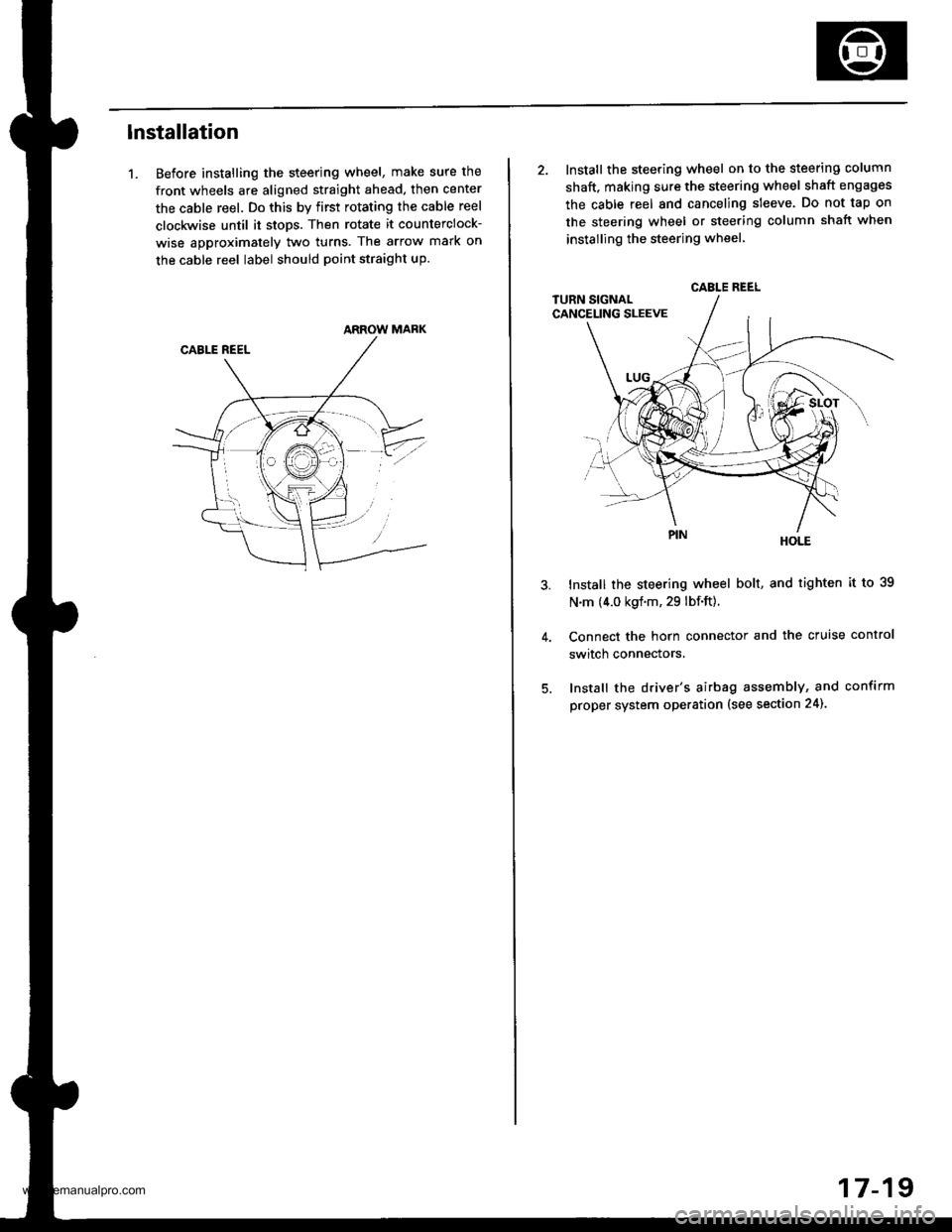
1. Before installing the steering wheel, make sure the
front wheels are aligned straight ahead, then center
the cable reel. Do this by first rotating the cable reel
clockwise until it stops. Then rotate it counterclock-
wise approximately two turns. The arrow mark on
the cable reel label should point straight up.
ARROW MARK
2. Install the steering wheel on to the steering column
shaft, making sure the steering wheel shaft engages
the cable reel and canceling sleeve. Do not tap on
the steering wheel or steering column shatt when
instailing the steering wheel
HOLE
Install the steering wheel bolt, and tighten it to 39
N.m (4.0 kgf.m, 29 lbf.ft).
Connect the horn connector and the cruise control
switch connectors,
Install the driver's airbag assembly, and confirm
proper system operation (see section 24).
CABLE REEL
17-19
www.emanualpro.com
Page 867 of 1395
Steering Column
Inspection (cont'dl
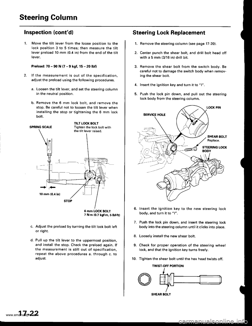
1.Move the tilt lever from the loose position to the
lock position 3 to 5 times; then measure the tilt
lever preload 10 mm (0.4 in) from the end of the tilt
rever.
Preload: 70 - 90 N (7 - 9 kgf, 15 - 20 lbf)
lf the measurement is out of the specification.
adjust the preload using the tollowing procedures.
a. Loosen the tilt lever, and set the steering column
in the neutral position.
b, Remove the 6 mm lock bolt. and remove the
stop. Be careful not to loosen the tilt lever when
installing the stop or tightening the 6 mm lock
bolt.
SPRING SCALENLT LOCK BOLTTighten the lock bolt withthe tilt lever raised.
L-_
d.
6 mm LOCK BOLT7 N.m (0,7 kgf.m, S tbtftl
Adjust the preload by turning the tilt lock bolt left
or ri9ht.
Pull up the tilt lever to the uppermost position.
and install the stop. Check the preload again. lf
the measurement is still out of specification,
repeat the above procedures a. through c. to
adjust.
17 -22
SHEAR BOLT
Steering Lock Replacement
1.
7.
Bemove the steering column (see page 17 -20).
Center punch the shear bolt, and drill bolt head off
with a 5 mm (3/16 in) drill bit.
Remove the shear bolt from the switch body. Be
careful not to damage the switch body when remov-
ing the shear bolt.
Insert the ignition key and turn it to "1".
Push the lock pin down, and pull out the steering
lock body from the steering column.
Insert the ignition key to the new steering lock
body, and turn it to "1".
Push the lock pin down, and insen the steering lock
body into the steering column until it clicks into place.
Loosely installthe new shear bolt.
Check tor proper operation of the steering wheel
lock, and that the ignition key turns freely.
Tighten the shear bolt untilthe hex head twists off.
TWIST.OFF PORNON
8.
10.
SHEAR BOLTReplace.
www.emanualpro.com
Page 897 of 1395
Power Steering Gearbox
Installation (cont'd)
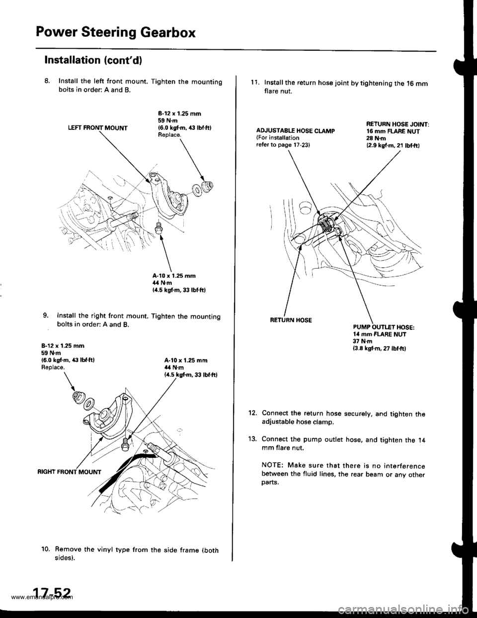
8, Install the left front mount. Tighten the mountingbolts in order: A and B.
LEFT FRONT MOUNT
B-12 x 1,25 mm59Nm(6.0 kgtm,,€ lbl.ftlReplaca.
9. Instsll the right front mount, Tighten the mountingbolts in order: A and B.
B-12 x 1.25 mm59 N.m16.0 ks[.m, ,|:| lbf.ftlReplace.
A-10 x 1.25 mm4,1 N.mla.s kgt m, 33 lbf.ft)
A-10 x 1.25 mma,a N.m
10. Remove the vinyl type from the side frame (both
sides).
17-52
11. Installthe return hose joint by tightening the 16 mmflare nut.
AD.'USTAB[T HOSE CLAMP(For installationreter to page 17,23)
RETURN HOSE JOINT:16 mm FLARE NUT28 N.m12.9 kg{.m.21 lbt{t)
14 mm FLARE NUT37 N.m(3.8 ksf.m, 27 lbl'frl
't2.
13.
Connect the return hose securely. and tighten theadjustable hose clamp.
Connect the pump outlet hose, and tighten the l4mm flare nut.
NOTE: Make sure that there is no interferencebetween the fluid lines, the rear beam or any otherparts.
www.emanualpro.com
Page 903 of 1395
Front Toe Inspection/Adjustment
Use commercially-available computerized four wheel
alignment equipment to measure wheel alignment (caster,
camber, toe, and turning angle). Follow the equipment
manufacturer's instructions,
3.
1.Check the tire pressure.
Center the steering wheel spokes.
Check the toe with the wheels pointed straight
ahead.
Front toe-in: 0 i 3 mm {0 t 1/8 inl
- lf adjustment is required, go on to step 4.
- lf no adjustment is required, remove alignment
equipment.
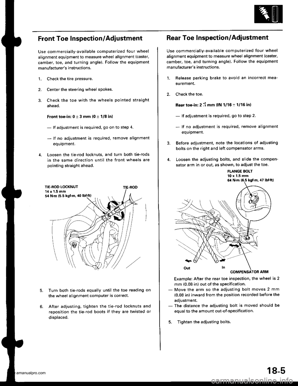
Loosen the tie-rod locknuts, and turn both tie-rods
in the same direction until the front wheels are
pointing straight ahead.
5.Turn both tie-rods equally until the toe reading on
the wheel alignment computer is correct.
After adjusting, tighten the tie-rod locknuts and
reposition the tie-rod boots if they are twisted or
displaced.
sir N m (5.5 kgJ.m, 'O lbf.ft)
Rear Toe Inspection/Adjustment
Use commercially-available computerized four wheel
alignment equipment to measure wheel alignment (caster,
camber. toe, and turning angle). Follow the equipment
manufacturer's instructions.
Release parking brake to avoid an incorrect mea-
surement.
Check the toe.
Ro8r toe-in: 2 :1 mm {lN l/16:t 1/16 in,
- lf adjustment is required, go to step 2.
- lf no adiustment is required. remove alignment
equrpmenr.
Before adjustment, note the locations of adjusting
bolts on the right and left compensator arms.
Loosen the adjusting bolts, and slide the compen-
sator arm in or out. as shown, to adiust the toe.
1.
FLANGE BOLT'10 x 1.5 mm
COMPENSATOR ARM
Example: After the rear toe inspection, the wheel is 2
mm (0.08 in) out of the specification.- Move the arm so the adjusting bolt moves 2 mm
{0.08 in) inward from the position recorded before the
adjustment.- The distance the adjusting bolt is moved should be
equal to the amount out-of-specification.
5. Tighten the adjusting bolts.
6a N.m 16.5 kgf.m, 47 lbf'ftl
18-5
www.emanualpro.com
Page 909 of 1395
12.
13.
14.
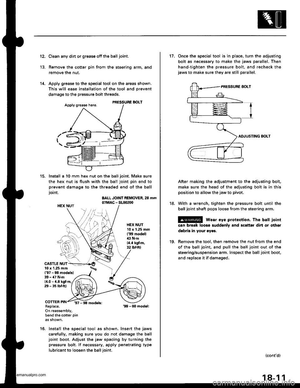
Clean any dirt or grease off the ball joint.
Remove the cotter pin from the steering arm, and
remove the nut.
Apply grease to the special tool on the areas shown.
This will ease installation of the tool and prevent
damage to the pressure bolt threads.
PRESSURE BOLT
lnstall a 10 mm hex nut on the ball joint. Make sure
the hex nut is flush with the ball joint pin end to
prevent damage to the threaded end of the ball
joint.
BALL JOINT REMOVER, 28 mm07MAC - SL(x)2(x)HEX NUT
HEX NUT10 x 1.25 mm('99 modcll43 N.mlit.a kgl.m.32 tbtft)
37 -98 models:
tc.
6:)
CASTLE NUT10 x '1.25 mm
l'97 - 98 modcls)39 - 47 N.m{4.0 - 4.829 - 3s rbtftt
COTTERReplace.On re6ss€mbly,bend the cofter pin
16. Install the special tool as shown. Insert the jaws
carefully, making sure you do not damage the balljoint boot. Adiust the jaw spacing by turning the
pressure bolt. lf necessary, apply penetrating type
lubricant to loosen the ball ioint.
'99 -00 modol:
18.
17. Once the special tool is in place, turn the adjusting
bolt as necessary to make the jaws parallel. Then
hand-tighten the pressure bolt, and recheck thejaws to make sure they are still parallel.
ADJUSTING BOLT
After making the adjustment to the adjusting bolt,
make sure the head of the adjusting bolt is in this
position to allow the jaw to pivot.
With a wrench, tighten the pressure bolt until the
ball joint shaft pops loose from the steering arm.
@ wear eye protection. The balt iointcan break loose suddenly and scatter dirt or other
dsbris in your ey€s.
Remove the tool, then remove the nut from the end
of the ball joint, and pull the ball joint out of the
steering/suspension arm. Inspect the ball joint boot.
and replace it if damaged.
(cont'dl
1(|
18-1 1
www.emanualpro.com
Page 1045 of 1395
Seats
Rear Seat Removal and Installation
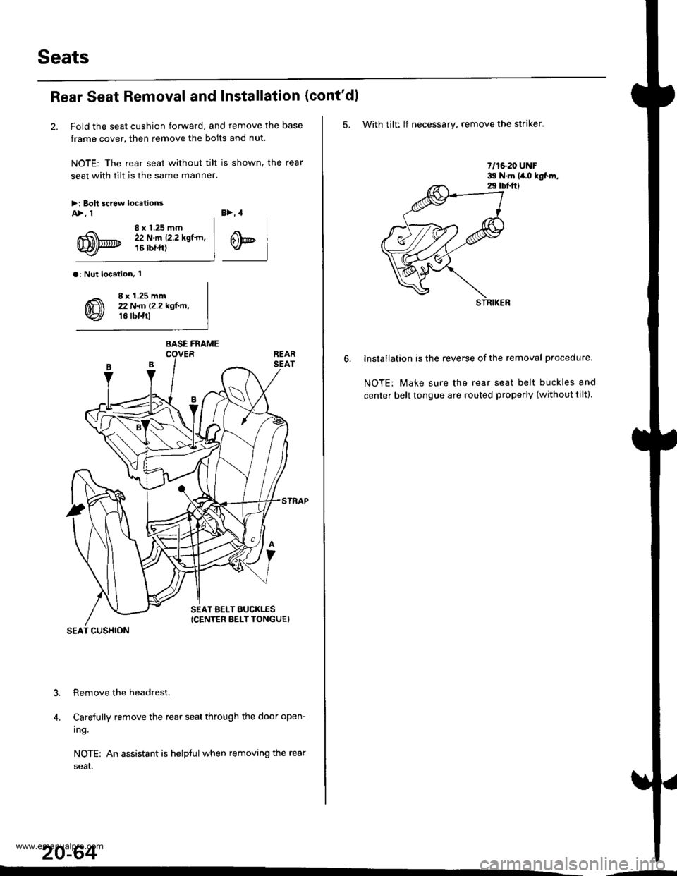
2. Fold the seat cushion forward, and remove the base
frame cover, then remove the bolts and nut.
NOTE: The rear seat without tilt is shown, the rear
seat with tilt is the same manner.
>i Boh screw locetionsA>, 1
8 x 1.25 mm22 N.m {2.2 kgf.rn,16 rbtft)
B>, 4
@t
a: Nut loc.iion, 'l
8 x 1.25 mm22 N
Carefully remove the rear seat through the door open-
ing.
NOTE: An assistant is helptul when removing the rear
seaI.
20-64
?
4.
BASE FRAME
SEAT BELT BUCKTES(CENTER BELT TONGUEI
SEAT CUSHION
(cont'dl
5. With tilt: lf necessary, remove the striker.
lnstallation is the reverse of the removal procedure.
NOTE: Make sure the rear seat belt buckles and
center belt tongue are routed properly (without tilt).
.-
www.emanualpro.com
Page 1050 of 1395
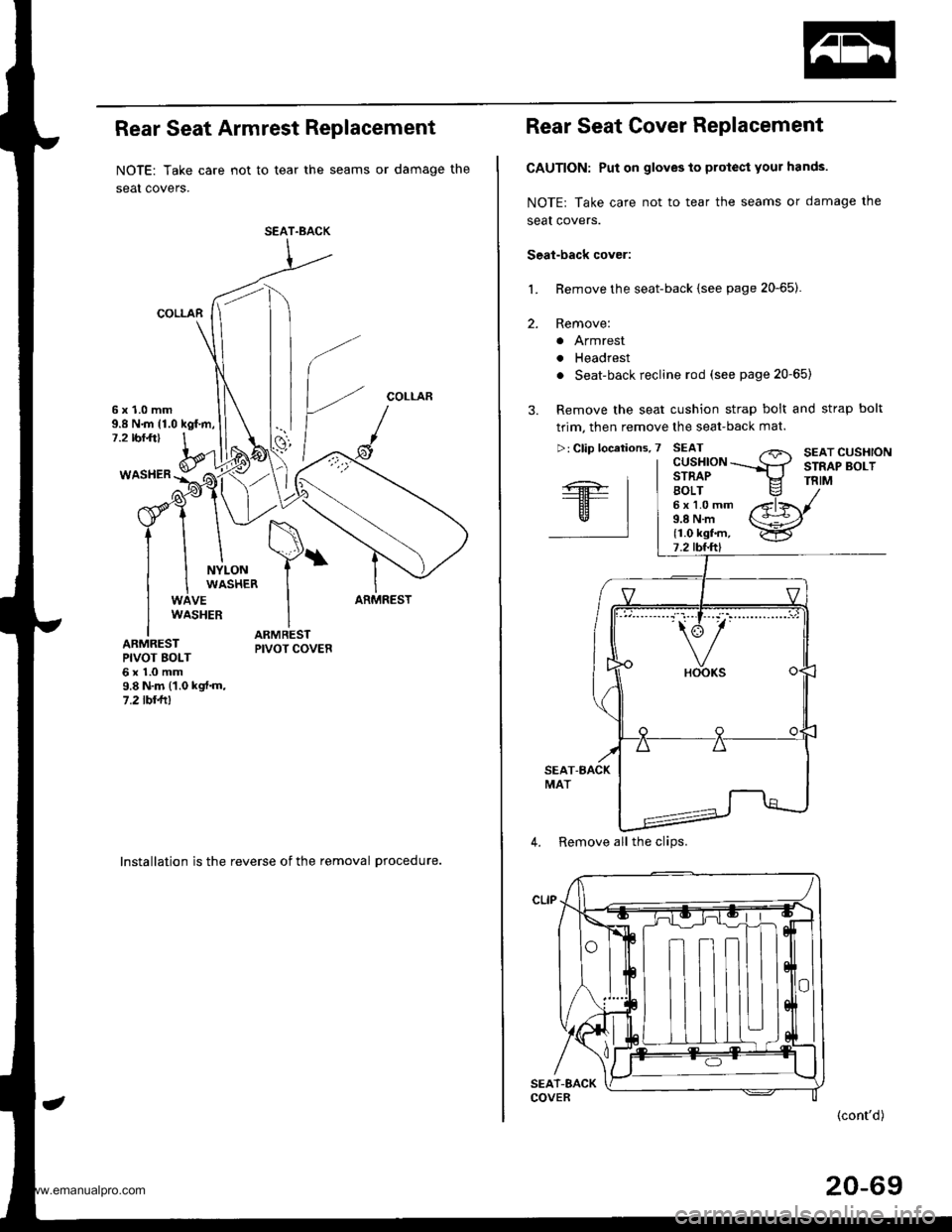
Rear Seat Armrest Replacement
NOTE: Take care not to tear the seams or damage the
seat covers.
COLLAR
COLLAR6x1.0mm9.8 N.m {1.0 kgf.m,7.2 rbr.ft)
WASHER
NYLONWASHER
VEARMRESTWASHER
ARMRESTPIVOT BOLT6x1.0mm9.8 N.m (1.0 kgt.m,7.2lbllll
lnstallation is the reverse of the removal procedure.
SEAT.BACK
Rear Seat Cover Replacement
CAUTION: Put on gloves to protect your hands.
NOTE: Take care not to tear the seams or damage the
seal covers.
Seal-back cover:
Remove the seat-back {see page 20-65).
Remove:
a Armrest
. Headrest
. Seat-back recline rod (see page 20-65)
Remove the seat cushion strap bolt and strap bolt
trim, then remove the seat-back mat.
L
2.
"'---.' t.-r" t-- i,': "" '
4. Remove all the clips.
(cont'd)
20-69
www.emanualpro.com
Page 1062 of 1395
Adjustment
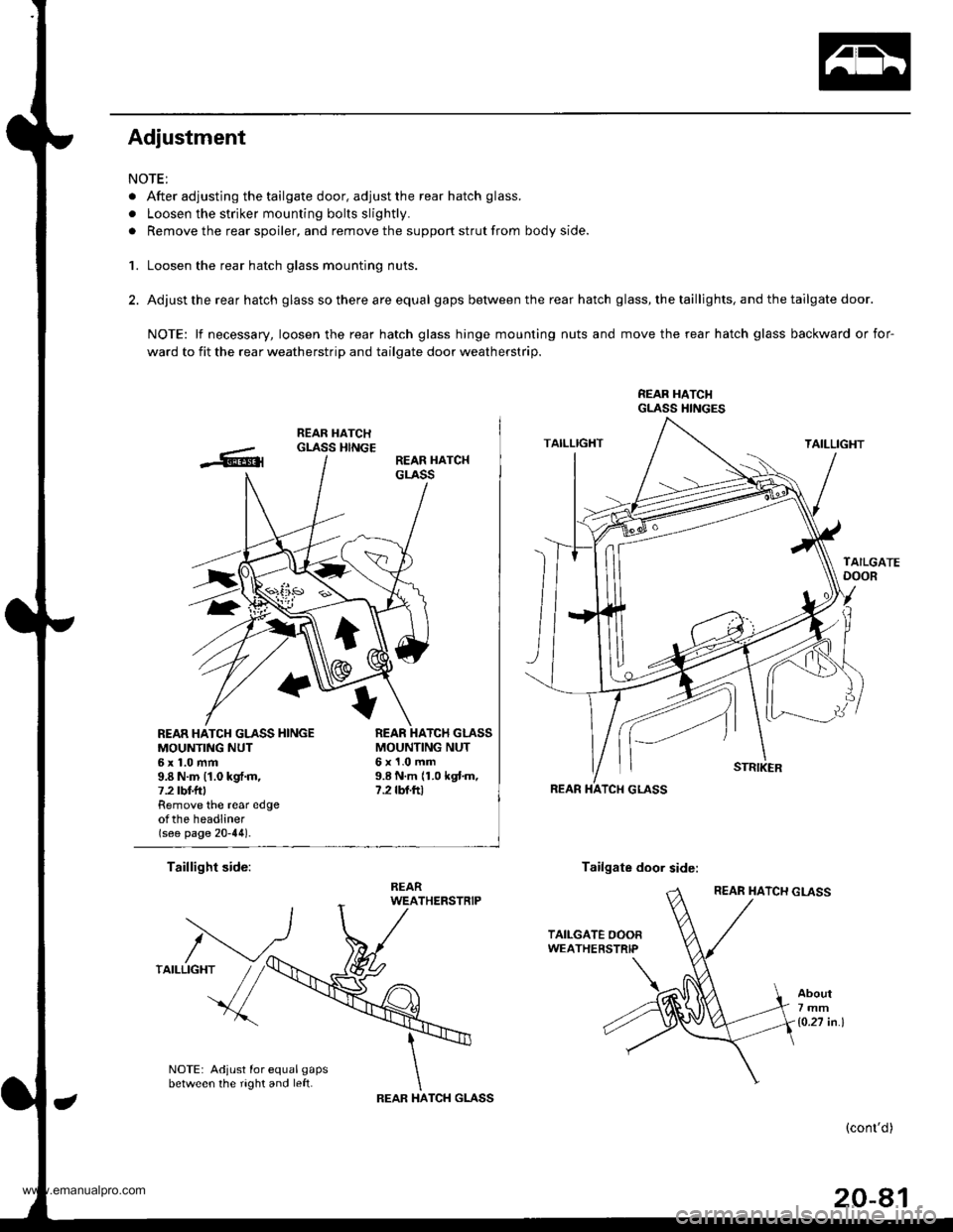
NOTE:
. After adjusting the tailgate door, adjust the rear hatch glass.
. Loosen the striker mounting bolts slightly.
. Remove the rear spoiler, and remove the support strut from body side.
1. Loosen the rear hatch glass mounting nuts.
2. Adjust the rear hatch glass so there are equal gaps between the rear hatch glass, the taillights, and the tailgate door.
NOTE: lf necessary, loosen the rear hatch glass hinge mounting nuts and move the rear hatch glass backward or for-
ward to fit the rear weatherstrip and tailgate door weatherstrip.
REAR HATCI{GLASS HINGES
REAR HATCH GLASS HINGEMOUNTING NUT6x1.0mm9.8 N.m (1.0 kgf.m,7.2 tbt f Remove the rear edgeotthe headliner(see page 20-44).
MOUNTING NUT6x1.0mm9.8 N.m 11.0 kgtm,7.2 rbf.ftt
Taillight side:Tailgate door side:
About7mm
1o.27 in.l
NOTE: Adjust for equal gapsbetween the right and left.TCH GLASSIHAREAR
(cont'd)
20-81
www.emanualpro.com