lock HONDA CR-V 1997 RD1-RD3 / 1.G Workshop Manual
[x] Cancel search | Manufacturer: HONDA, Model Year: 1997, Model line: CR-V, Model: HONDA CR-V 1997 RD1-RD3 / 1.GPages: 1395, PDF Size: 35.62 MB
Page 999 of 1395
Doors
Tailgate Door Latch and Latch Stop
Replacement (cont'd)
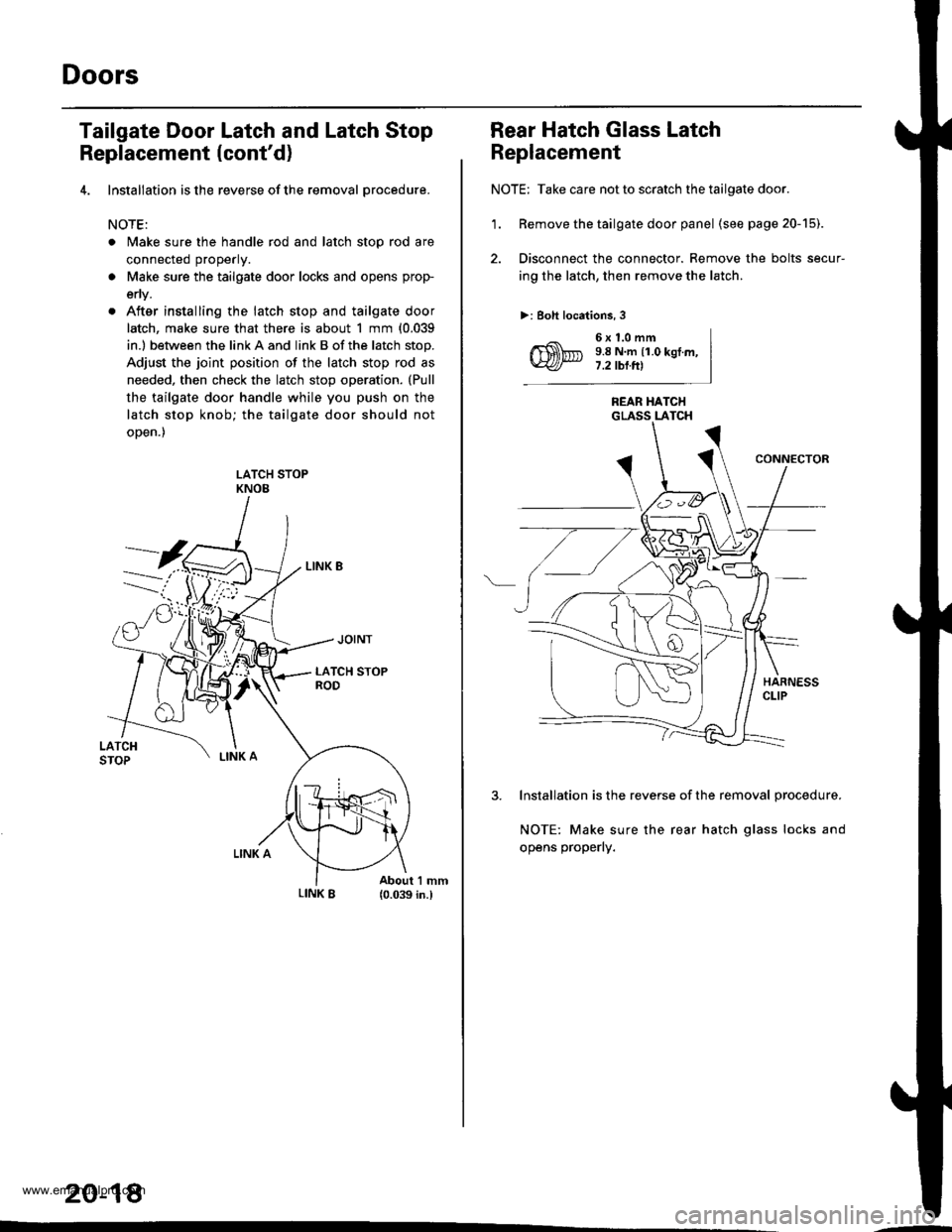
4. lnstallation is the reverse of the removal orocedure.
NOTE:
. Make sure the handle rod and latch stop rod are
connected properly.
a Make sure the tailgate door locks and opens prop-
env.
. After installing the latch stop and tailgate door
latch, make sure that there is about 1 mm {0.039
in.l between the link A and link B of the latch stop.
Adjust the joint position of the latch stop rod as
needed, then check the latch stop operation. (Pull
the tailgate door handle while you push on the
latch stop knob; the tailgate door should not
oDen.)
LATCH STOPKNOE
20-18
Rear Hatch Glass Latch
Replacement
NOTE: Take care not to scratch the tailgate door.
'1. Remove the tailgate door panel (seepage20-15).
2. Disconnect the connector. Remove the bolts secur-
ing the latch, then remove the latch.
>: Boh locations, 3
6x1.0mm9.8 N.m {1.0 kgI.m,7.2 tbl.Itl
REAR HATCHGLASS LATCH
3. Installation is the reverse of the removal procedure.
NOTE: Make sure the rear hatch glass locks and
opens properly.
www.emanualpro.com
Page 1000 of 1395
Rear Hatch Glass Lock Cylinder
Replacement
NOTE: Take care not to scratch the tailgate door.
1. Remove the tailgate door panel (see page 20-15).
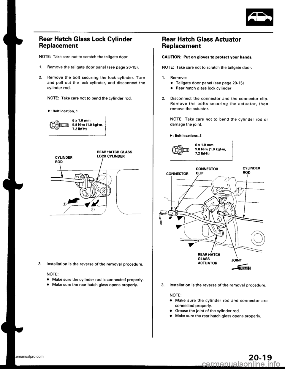
2. Remove the bolt securing the lock cylinder. Turn
and pull out the lock cylinder, and disconnect the
cylinder rod,
NOTE: Take care not to bend the cylinder rod.
>: Bolt location. 1
6x1.0mm9.8 N.m {1.0 kg .m,
7 .2 tbt.lll
REAR HATCH GLASS
J.Installation is the reverse of the removal procedure.
NOTE:
. Make sure the cylinder rod is connected properly.
. Make sure the rear hatch glass opens properly.
Rear Hatch Glass Actuator
Replacement
CAUTION: Put on gloves to protsct your hands.
NOTE: Take care not to scratch the tailgate door.
1. Remove;
o Tailgate door panel (see page 20-'15)
. Rear hatch glass lock cylinder
2. Disconnect the connector and the connector clip.
Remove the bolts securing the actuator, then
remove the actuator.
NOTE: Take care not to bend the cylinder rod or
damage the joint.
>: Bolt locations, 3
6x1.0mm9.8 N.m 11.0 kgt.m,7.2 tbt.ft)
CONNECTOR
CONNECTOR
REAR HATCHGLASSACTUATORJOINT
-6{
Installation is the reverse of the removal procedure.
NOTE:
. Make sure the cylinder rod and connector are
connected properly.
. Grease the joint of the cylinder rod.
. Make sure the rear hatch glass opens properly.
20-19
www.emanualpro.com
Page 1008 of 1395
Power Mirror Replacement
NOTE: Tako care not to scratch the mirror, mirror mount
cover and door.
1. Lower the door glass fully.
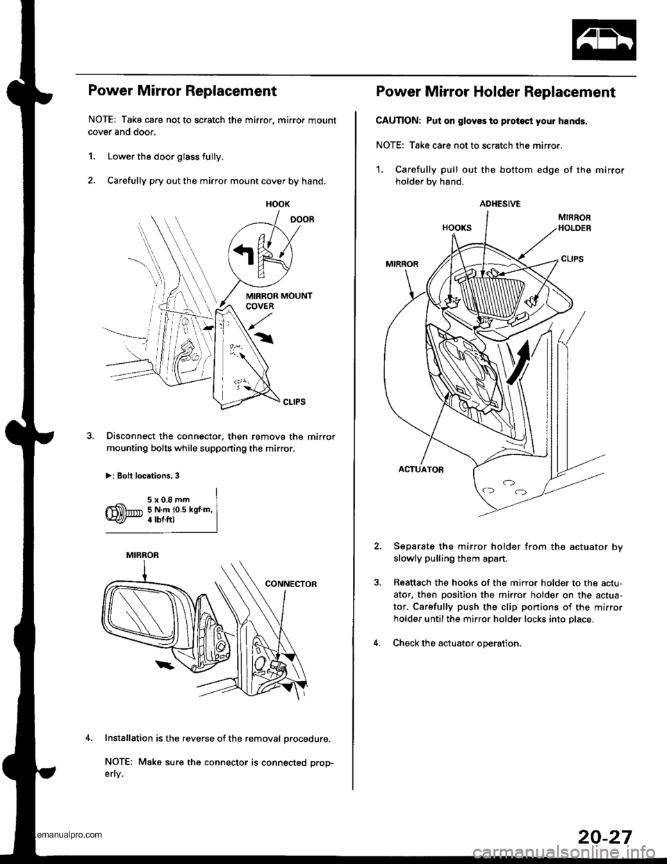
2. Carefully pry out the mirror mount cover by hand,
,l
Disconnect the connector. then remove the mirror
mounting bolts while supponing the mirror,
>: Boh locations, 3
Installation is the reverse of the removal procedure,
NOTE: Make sure the connector is connected prop-
efly.
HOOK
MIRROR
Power Mirror Holder Replacement
CAUTION: Put on glovss to protest you. hands.
NOTE: Take care not to scratch the mirror.
1, Carefully pull out the bottom edge of the mirror
holder bv hand.
Separate the mirror holder from the actuator bv
slowly pulling them apart.
Reattach the hooks of the mirror holder to the actu-
ator, then Dosition the mirror holder on the actua-
tor. Carefully push the clip portions of the mirror
holder untilthe mirror holder locks into place.
Check the actuator ooeration.
ADHESIVE
20-27
www.emanualpro.com
Page 1024 of 1395
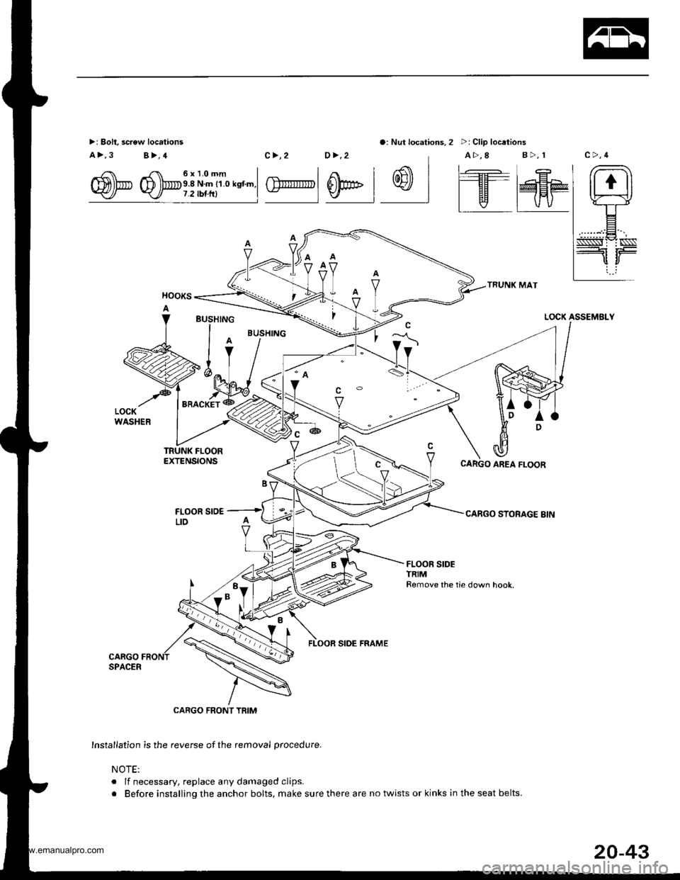
>: Bolt, screw locations
a>,3 B>,4
o: Nut locations, 2 >: Clip locations
TRUNK MAT
CARGO STORAGE BIN
/ rr. 6xl.Omm I
m)b D lbe.8 Nm r1.o ksnm.l-
c>,2 0>,2 A>,8 B>,r
| .€ | r- -I At I tl1|r' t I l���'---llH- | E
GlrrIIITTpl 0pE l w I l--Tr@HPv | | v I vv
LOCK ASSEMBLY
TRUNK FLOOREXTENSIONS
FLOOR SrO€LID
FLOOR SIDE FRAME
CARGO FRONT TRIM
Insta,lation is the reverse of the removal procedure.
NOTE:
. lf necessary, replace any damaged clips.
r Before installing the anchor bolts, make sure there are no twists or kinks in the seat belts.
BUSHING
l^IV
>ilv '%L
"ro"*i*
CARGO AREA FLOOR
l*,hl
20-43
www.emanualpro.com
Page 1056 of 1395
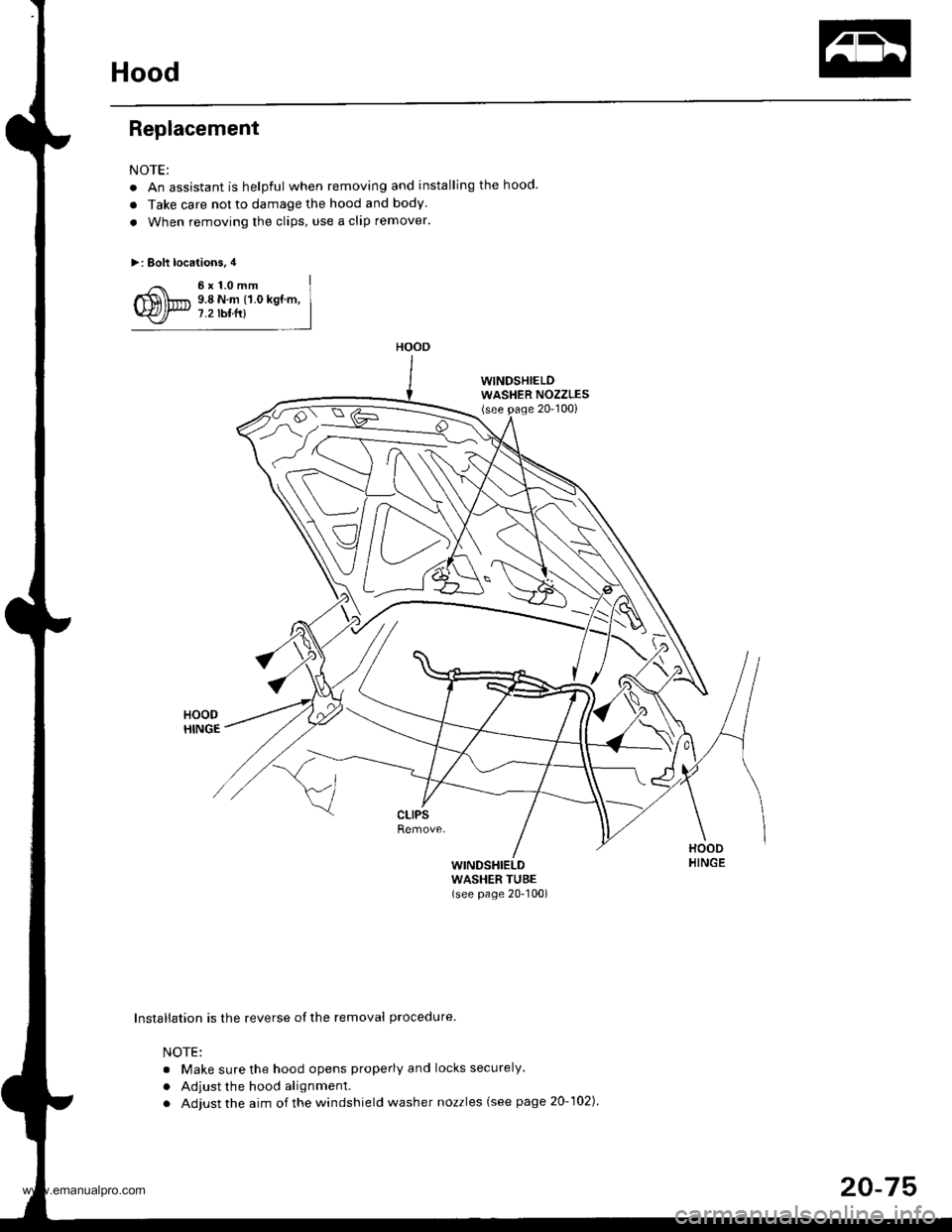
Hood
Replacement
NOTE:
. An assistant is helpful when removing and installing the hood.
a Take care not to damage the hood and body
. When removing the clips, use a clip remover.
>: Bolt locations, 4
6x1.0mm9.8 N.m {1.0 kgt.m,7.2 tbtfr)
WINDSHIELDWASHER NOZZLES(see page 20-100)
G
{
\HOODHINGEWINDSHIELDWASHER TUBE(see page 20-100)
Installation is the reverse of the removal procedure
NOTE:
. Make sure the hood opens properly and locks securely.
. Adjust the hood alignment.
. Adjust the aim of the windshield washer nozzles (see page 20-102)
HOOD
20-75
www.emanualpro.com
Page 1063 of 1395
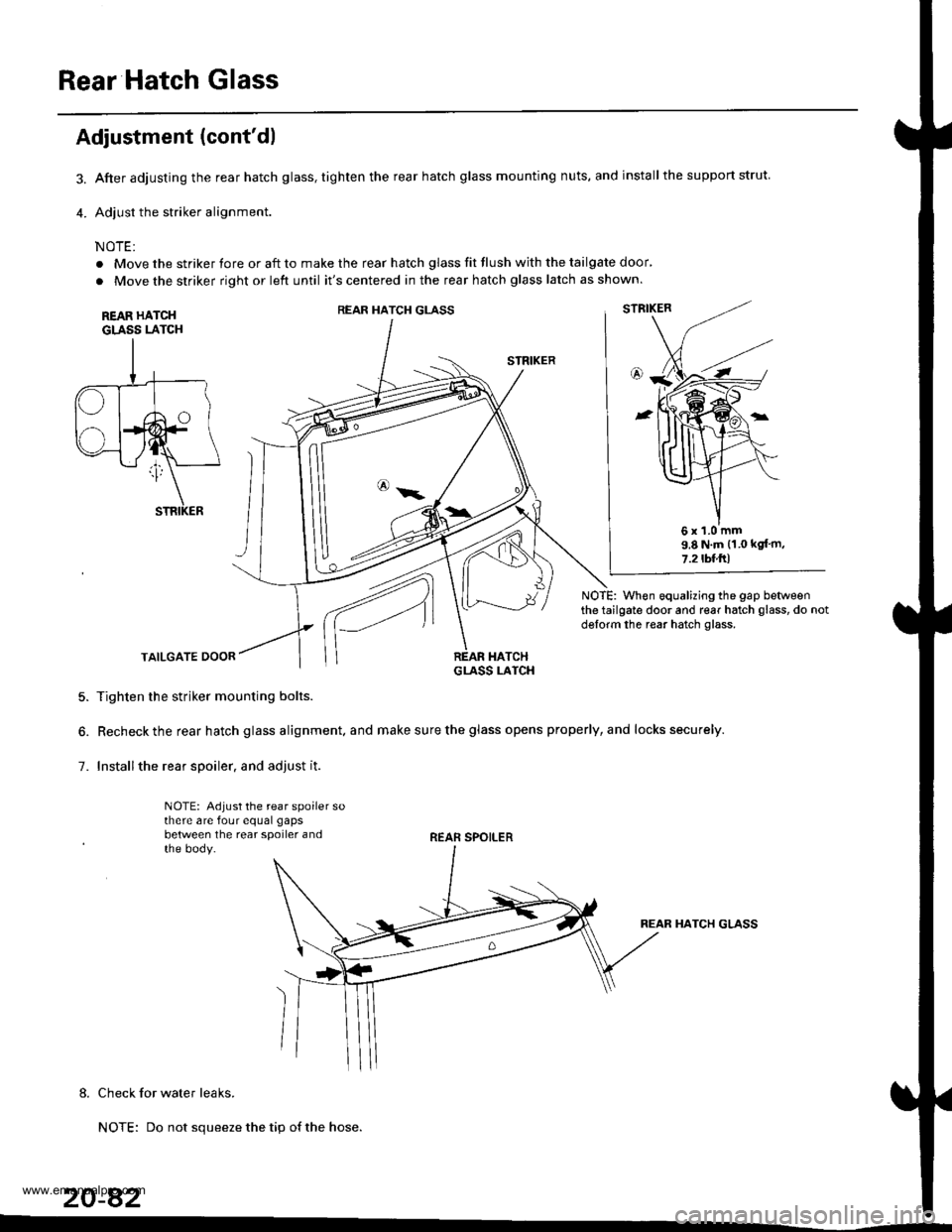
Rear Hatch Glass
3.
4.
Adjustment (cont'dl
After adjusting the rear hatch glass, tighten the rear hatch glass mounting nuts, and installthe support strut.
Adjust the striker alignment.
NOTE:
. Move the striker fore or aft to make the rear hatch glass fit flush with the tailgate door'
. Move the striker right or left until it's centered in the rear hatch glass latch as shown.
REAR HATCHGLASS LATCH
STRIKER
NOTE: When equalizing the gap betweenthe tailgate door and rear hatch glass, do notdglorm the rear hatch glass.
TAILGATE DOOR
5. Tighten the striker mounting bolts.
6. Recheck the rear hatch glass alignment. and make sure the glass opens properly, and locks securely.
7. Installthe rear spoiler. and adjust it.
NOTE: Adjust the rear spoiler sothere are four equal gaps
between the rear spoiler andthe body.REAR SPOILER
REAR HATCH GLASS
8. Check for water leaks.
NOTE: Do not squeeze the tip of the hose.
20-82
REAR HATCH GLASS
6x1.0mm9.8 N.m (1.0 kgt'm,
7.2tbl.ftl
www.emanualpro.com
Page 1076 of 1395
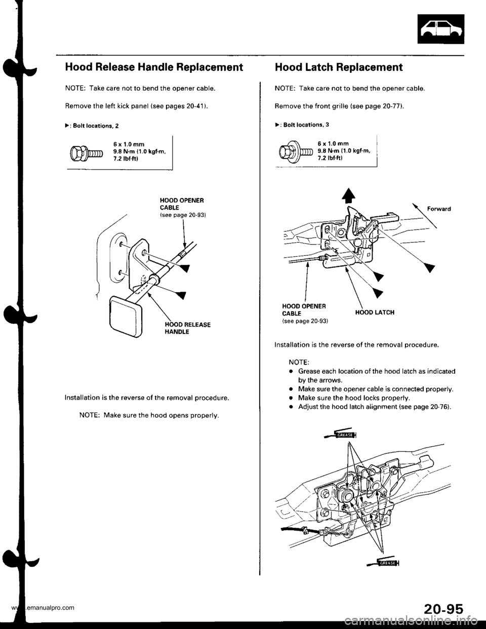
Hood Release Handle Replacement
NOTE: Take care not to bend the opener cable.
Remove the left kick panel (see pages 20-41).
>: Eolt locations.2
6x1.0mm9.8 N.m {1.0 kgl.m,7.2 tbl.tll
HOOD OPENERCABLE{see page 20-93)
Installation is the reverse of the removal procedure.
NOTE: Make sure the hood opens properly.
Hood Latch Replacement
NOTE: Take care not to bend the opener cable.
Remove the front grille (see page 20-77).
>: Bolt locations,3
6x1.0mm9.8 N.m {1.0 kgf.m,7.2 tbt.ftl
HOOO LATCH
Installation is the reverse of the removal procedure.
NOTE;
. Grease each location ofthe hood latch as indicated
by the arrows.
. Make sure the opener cable is connected properly.
. Make sure the hood locks properly.
. Adjust the hood latch alignment (see page 20-76).
20-95
www.emanualpro.com
Page 1077 of 1395
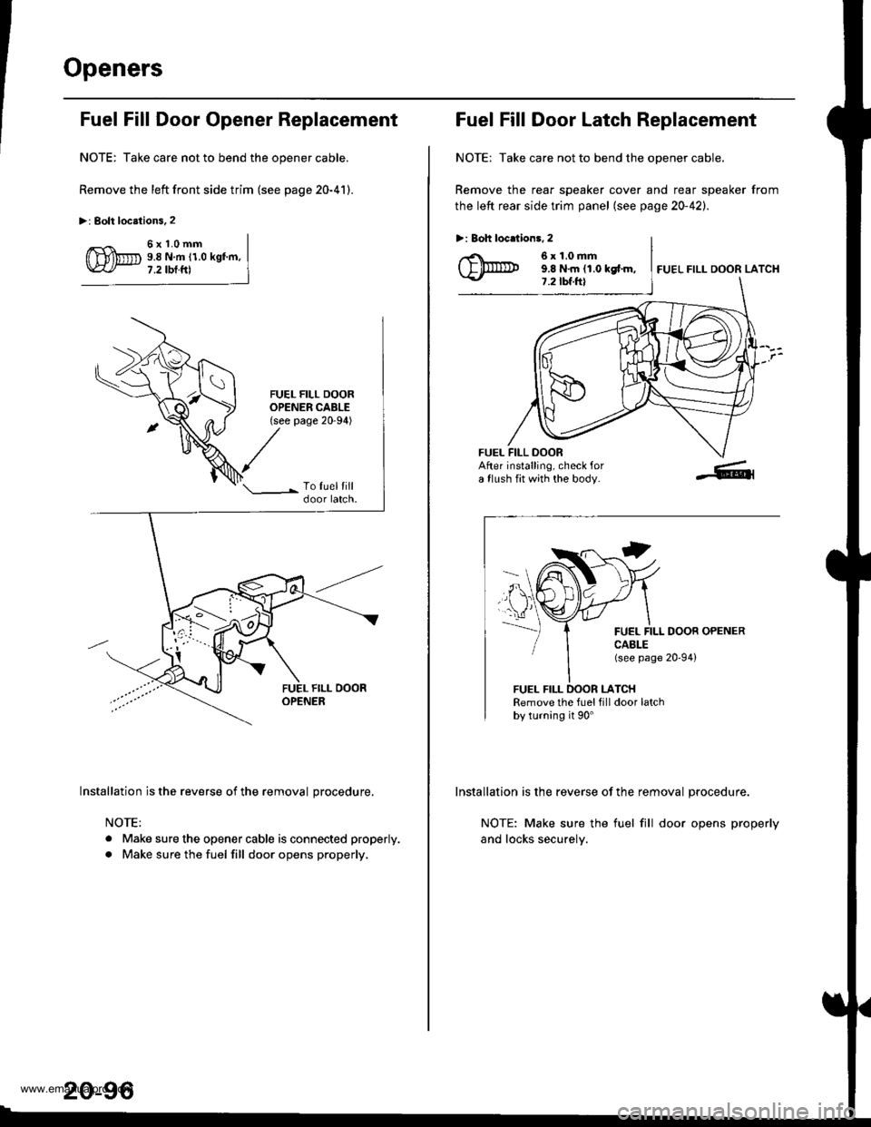
Openers
Fuel Fill Door Opener Replacement
NOTE: Take care not to bend the opener cable.
Remove the left front side trim (see page 20-41).
>: Bolt locstions.2
5x1.0mm9.8 N.m (1.0 kgf.m,7.2 tbt.ftl
FUEL FILL DOOROPENER CABLE(see page 20-94)
Installation is the reverse of the removal procedure.
NOTE:
. Make sure the opener cable is connected properly.
. Make sure the fuel fill door opens properly,
20-96
Fuel Fill Door Latch Reolacement
NOTE: Take care not to bend the opener cable.
Remove the rear speaker cover and rear speaker from
the left rear side trim panel (see page 20-42).
>: Boh locdions, 2
6x1.0mm9.8 N.m (1.0 kgf.m,7.2 tbf.ft)FUEL FILL DOOR LATCH
FUEL FILL DOORAfter installing, check fora flush fit with the body.
CAELE(see Page
LATCH
DOOR OPENER
20,94)
FUEL
FUEL FILLRemove the fuel fill door latchby turning it 90'
Installation is the reverse of the removal procedure.
NOTE: Make sure the fuel fill door opens properly
and locks securely.
www.emanualpro.com
Page 1134 of 1395
Evaporator Temperature
SensorPower Transistor
Test
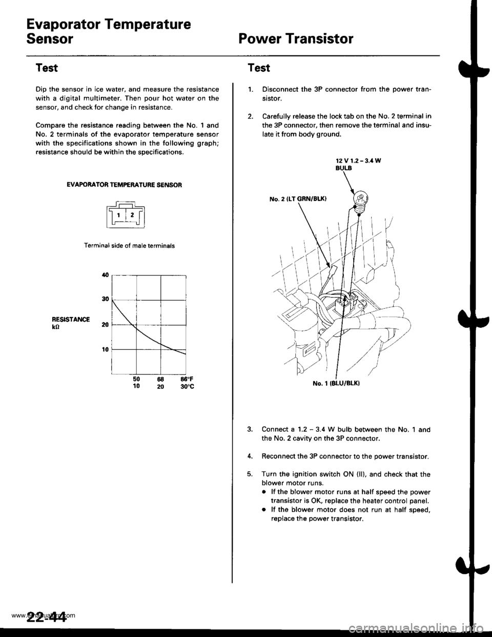
Dip the sensor in ice water, and measure the resistance
with a digital multimeter. Then pour hot water on the
sensor, and check lor change in resistance.
Compare the resistance reading between the No. | 8nd
No. 2 terminals of the evaporator temperature sensor
with the specifications shown in the following graph;
resistance should be within the specifications.
EVAPOBATOR TEMPERATURE SENSOB
Terminal side ol male terminals
4
RESISTANCEko
t0
50 68 86.F10 20 30'c
22-44
12V 1.2-3.1W
No. 2 ILT GRN/BLK)
No. I IBLU/BLK)
Test
1.Disconnect the 3P connector from the oower tran-
st$or.
Carefully release the lock tab on the No. 2 terminal in
the 3P connector, then remove the terminal and insu-
late it from body ground.
Connect a 1.2 - 3.4 W bulb between the No, 1 and
the No,2 cavity on the 3P connectol
Reconnect the 3P connector to the power transistor.
Turn the ignition switch ON (ll). and check that the
blower motor runs.
a lf the blower motor runs at half soeed the oower
transistor is OK, replace the heater control panel.
. lf ths blower motor does not run at half soeed,
reDlaca the Dower transistor.
www.emanualpro.com
Page 1145 of 1395
A/C System Torque Specifications
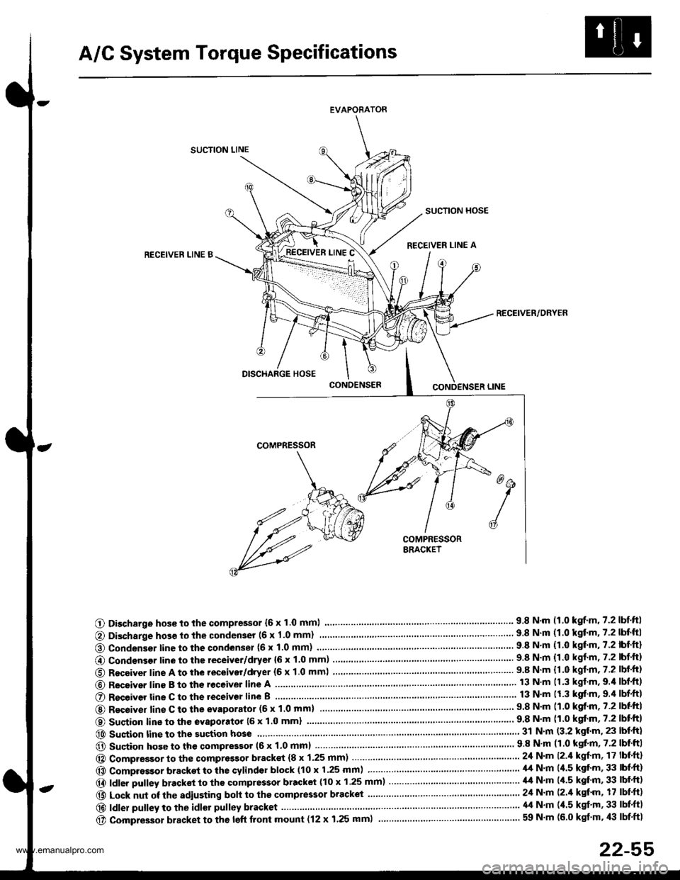
EVAPORATOR
SUCTION LINE
SUCTION HOSE
RECEIVER LINE ARECEIVEN LINE B
RECEIVER/ORYER
O Discharge hos€ to the compressor {6 x 1.0 mml.... 9.8 N.m 11.0 kgrf.m.7.2lbtftl
@ Condenser line to the condenser (6 x 1.0 mm)
@ Condensor line to the receiver/dryer {6 x 1.0 mm) ........9.8 N.m {1.0 kgf.m, 7.2 lbt.ft)
O Receiver line A to the receivor/dryer (6 x 1.0 mm) ...... ....................... 9.8 N.m {1.0 kgf.m.7.2 lbf.ft}
@ Receiver line B to th€ receive. line A
O R€ceiver tine C to the receivor line B
@ Recoiver line C to the evaporator (6 x 1'0 mml9.8 N'm (1.0 kgf.m,7.2lbtftl
O Sustion line to the evaporatot 16 x 1.0 mml
@ Sustion line to the suction hose...... 31 N.m (3.2 kgl.m, 23 lbf.ft)
@ Sucion hose to the qompressor (6 x 1.0 mm) .....'...' 9 8 N'm (1 0 kgt'm, 7'2 lbf'ftI
@ Compressor to the compressor bracket {8 x 1.25 mm) ... 24 N.m l2.il kgf'm, 17 lbf'ft}
@ Compressor bracket to the cylindsr block (10 x 1.25 mm) ................ ......... il,t N'm (4.5 kgt'm, 33 lbf'ft)
@ ldler pulley bracket to the compressor bracket (10 x 1.25 mm)..................... ,14 N.m (/r.5 kgf'm, 33 lbf'ft)
@ Lock nut of the sdiusting boh to the compressor bracket ......................... 24 N'm (2./t kgt'm, 17 lbf'ft)
@|d|erpu||eytotheid|orpu||eybracket.....'..........................'....\
.'.....'........'....44N.m(4.5kg''m'33|bf.f)
@ compressor bracket to the left front mount (12 x 1.25 mml ................... ............................ 59 N'm (6.0 kgt'm, /l:| lbf'ft1
22-55
www.emanualpro.com