reset HONDA CR-V 1997 RD1-RD3 / 1.G Service Manual
[x] Cancel search | Manufacturer: HONDA, Model Year: 1997, Model line: CR-V, Model: HONDA CR-V 1997 RD1-RD3 / 1.GPages: 1395, PDF Size: 35.62 MB
Page 959 of 1395
Troubleshooting Precautions
ABS lndicalor
1 lf the system is oK, the ABS indicator goes off two seconds after turning the ignition switch oN 1l) wathout staningthe engine, and then comes on again and goes off after two seconds. This occurs because the ABS control unit isturned on by the lG2 power source.2. The ABS indicator comes on when the ABS control unit detects a problem in the system. However, even thouoh thesystem is operating properly, the ABs indicator will come on too, under the following conditions:. Signal disturbance
. Wheel spin
. Only drive wheels rotate. Battery voltage fluctuates
To determine the actual cause of the problem, question the customer about the problem, taking these conditions intoconsideration:
3 When a problem is detected and the ABS indicator comes on, the indicator can stay on until the ignition switch isturned OFF, or it can automatically go off, depending on the mode.. Indicator stays on untilthe ignition switch is turned off: When the system is in the system down mode.. Indicator automatically goes off: When the system is in the control inhibition mode.4 The ABS indicator stays on when the system is reactivated without erasing the DTC, but it goes off after starting thevehicle.
When the wheel sensor system is faulty and the ABS indicator comes on. the algorithm of the system automatically turnsoff the ABS indicator after the wheel speed signal returns to the normal speed. Also, when the DTc is erased, the cpu isreset and the ABS indicator goes off when the system checked out normal by the initial diagnosis.Therefore, test-drive the vehicle after servicing the wheel sensor system. and be sure that the ABS indicator does notcome on.
5 When the ABS control unit outputs battery voltage to the gauge assembly, the ABS indicator ooes off.
Diagnostic Trouble Code (DTCI
1. The diagnostic trouble code (DTc) is memorized when a problem is detected and the ABS indicator does not go off,or when the ABS indicator comes on.The DTc is not memorized when the ABS indicator comes on unress the cpu is activated,2 The memory can hold any number of DTCs. However, when the same DTc is detected twice or more, the tater one iswritten over the old one.
Therefore, when the same problem is detected repeatedly, it is recorded as one DTC.3. The DTCs are indicated in the order of ascending number, not in the order they occur.4. The DTCS are memorized in the EEPROM (non-volatile memorv).Therefore, the memorized DTcs cannot be canceled by disconnecting the battery. perform the specified procedures toerase the DTCS.
Self-diagnosis
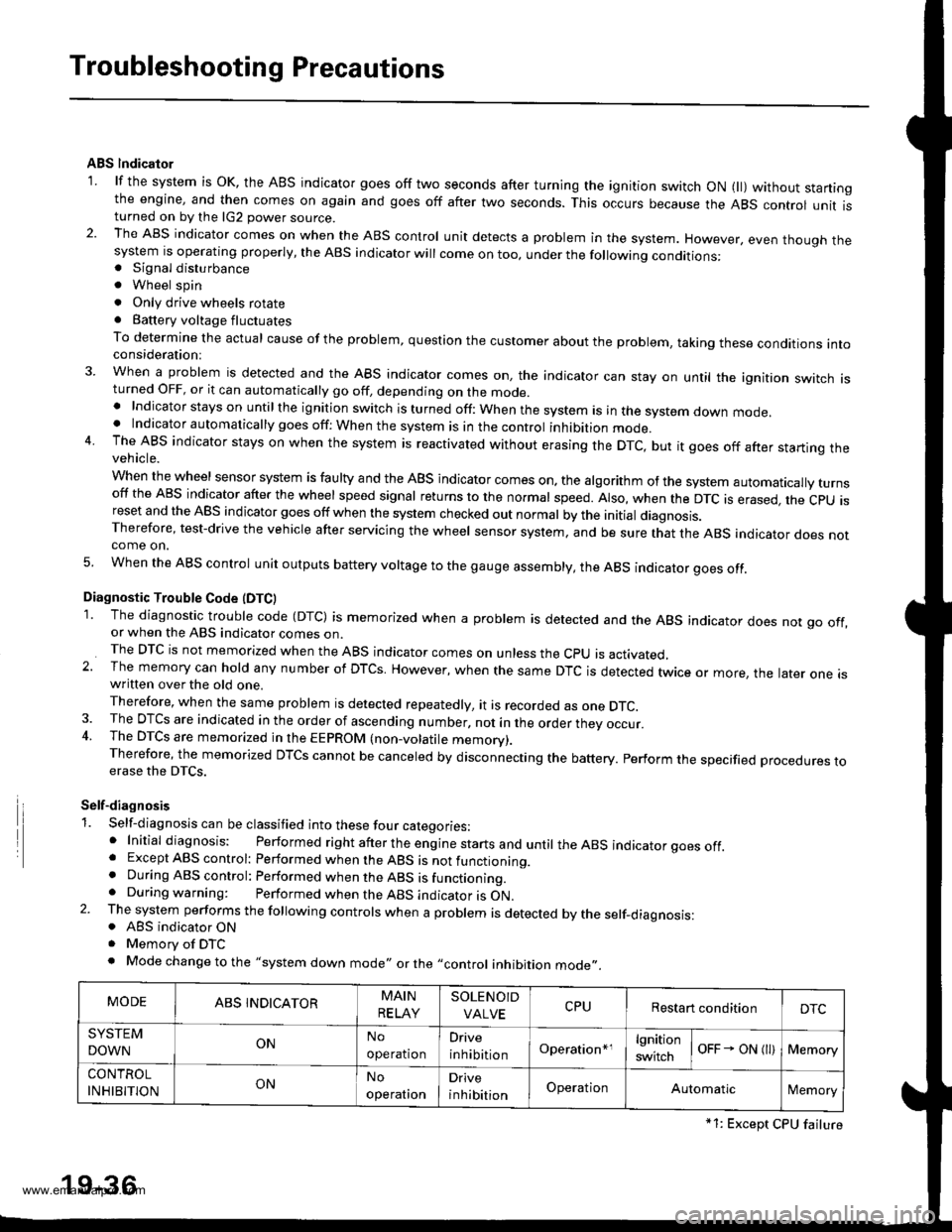
1. Self-diagnosis can be classified into these four categories:' Initial diagnosis: Performed right after the eng ine starts and untir theABS indicator goes off.. Except ABS control: Performed when the ABS is not functioning.. During ABS control: Performed when the ABS is functioning.. During warning: Performed when the ABS indicator is ON.2. The system performs the fo|owing contrors when a probrem is detected by the serf-diagnosis:. ABS indicator ON. Memorv of DTC. Mode changetothe "system down mode,, or the ,,control inhibition mode,,.
MODEABS INDICATORMAIN
RELAY
SOLENOID
VALVECPURestart conditionDTC
SYSTEM
DOWNONNo
operation
Drive
inhibitionOperation*rlgnition
switchoFF - ON l)Memory
CONTROL
INHIBITIONONNo
operal|on
Drive
inhibitionOperationAutomaticlMemory
*1: Except CPU failure
19-36
www.emanualpro.com
Page 1034 of 1395
Dashboard Removal and Installation
SRS components are located in this area. Review the SRS
component locations, precautions, and procedures in the
SRS section {24) before preforming repairs or service.
CAUTION:
. When prying with a flat-tip screwdriver, wrap h withprotective tap€, and apply protective tape around the
related parts to prevgnt damage.
. Put on gloves to prot€ct your hands.
NOTE:
. An assistant is helpful when removing and installing
the dashboard.
. Take care not to scratch the dashboard, bodv and
other related parts.
1.Make sure you have the anti-theft code for the
radio, then write down the frequencies for the
radio's preset buttons.
Disconnect the negative battery cable. and wait at
least three minutes before beginning work.
Removei
a Driver's dashboard lower cover and knee bolster(see page 20-48)
. Glove box (see page 20-49)
. Lower console cover and center pocket (A/T
model, see page 20-49)
. Center console and center upper pocket (M/T
model, see page 20-47)
. Center dashboard lower cover (see page 20-50)
. Power window switch (see page 20-51)
. Driver's side air vent (see page 20-52)
. Driver's side defogger trim (see page 20-52)
Disconnect the driver's airbag connector, and lower
the steering column (see section 17)
NOTE: To prevent damage to the steering column,
wrap it with a shop towel.
2.
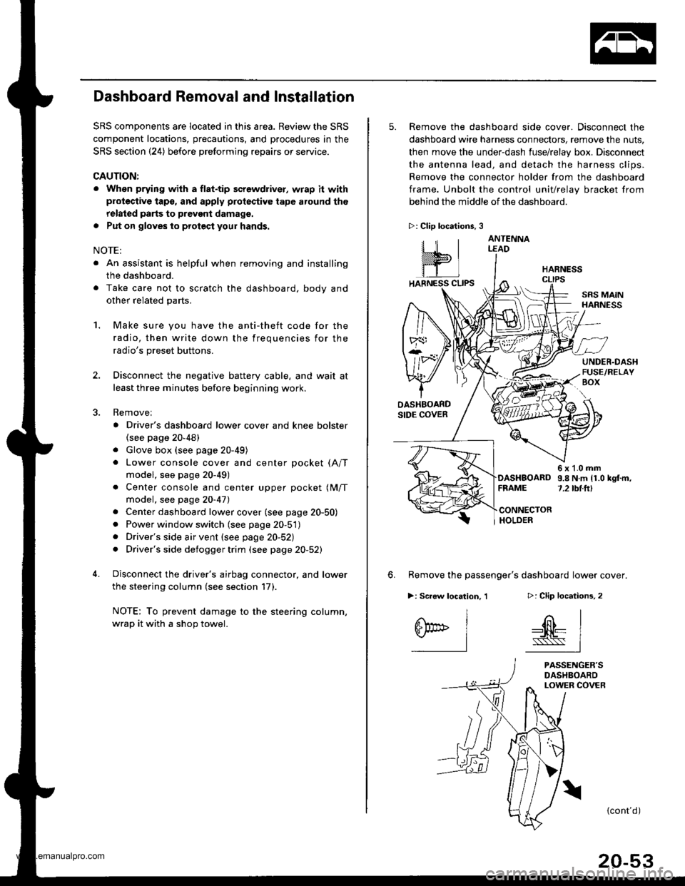
5. Remove the dashboard side cover. Disconnect the
dashboard wire harness connectors, remove the nuts,
then move the under-dash fuse/relay box. Disconnect
the antenna lead, and detach the harness clips.
Remove the connector holder from the dashboard
frame. Unbolt the control unit/relay bracket from
behind the middle of the dashboard.
HARNESS
6. Remove the passenger's dashboard lower cover.
D: Clip locations,
nl
-$t- Issj
I
ANTENNALEAD
>: Clip locations.
rttl
slllll
>: Scr€w location, 1
I
SF:oo I-l
SRS MAINHARNESS
UNDER.DASHFUSE/RELAYBOX
OASHBOARDSIDE COVER
6x1.0mm9.8Nm11.0kgf.m,7.2tbt.ftlDASHBOARDFFAME
CONNECTORHOLDER
PASSENGER'SDASHBOARDLOWER COVER
{cont'd)
www.emanualpro.com
Page 1101 of 1395
Self-diagnosis Function
The heater control panel has a self-diagnosis function.
Running the Self-diagnosis Function'97 mod€l:
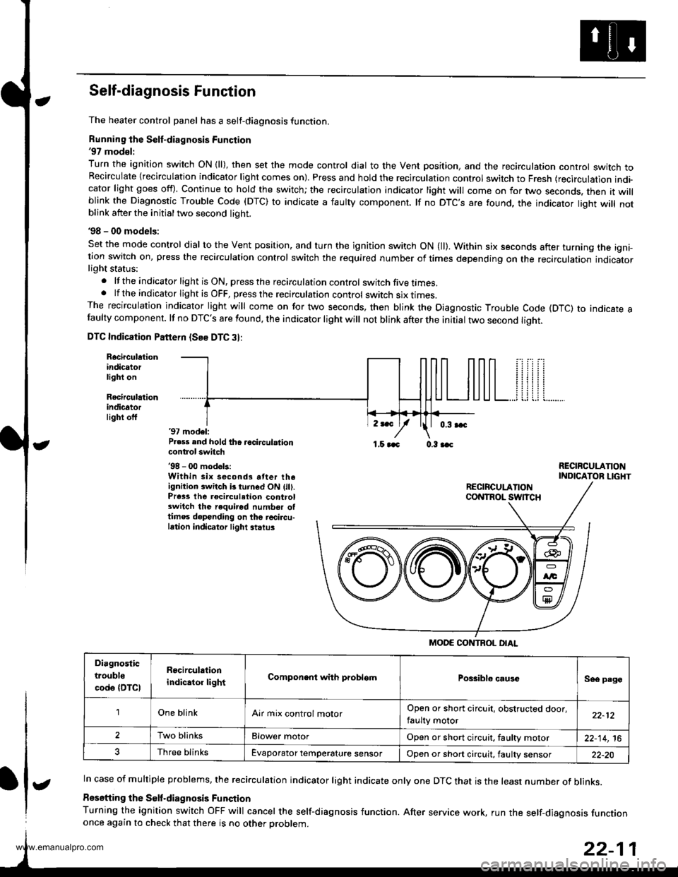
Turn the ignition switch ON {ll), then set the mode control dial to the Vent position, and the recirculation controt switch toRecirculate {recirculation indicator light comes on). Press and hold the recirculation control switch to Fresh (recirculation indi-cator light goes off). Continue to hold the switch; the recirculation indicator light will come on for two seconds. then it willblink the Diagnostic Trouble Code (DTC) to indicate a iaulty component. lf no DTC'S are found, the indicator liqht will notblink atter the initial two second light.
'98 - 00 models:
Set the mode control dial to the Vent position, and turn the ignition switch ON (ll). Within six seconds after turning the igni-tion switch on, press the recirculation control switch the required number of times depending on the recirculation indicatorlight status:
.lftheindicatorlightisON,presstherecirculationcontrol switch five times..lftheindicatorlightisOFF,presstherecirculationcontrol switch six I|mes.The recirculation indicator light will come on for two seconds, then blink the Diagnostic Trouble Code (DTC) to indicate afaulty component. lf no DTC'S are found, the indicator light will not blink after the initial two second liqht.
DTC Indicaiion Pattern {See DTC 3}:
Rocirculationindicatorlight on
Recirculrtionindicatorlighi off'97 model:P.ess and hold th6 recircul.tioncontrol switch'98 - 00 modek:Within six second3 atter theignition switch b turned ON (lll.Prass the rocirculation controlswitch the required number oltimes depending on the r6circu-lation indicator light striu3
,r*
/1.5 aaa 0.3 aac
RECIRCULANONINDICATOR LIGHT
In case of multiple problems, the recirculation indicator light indicate only one DTC that is the least number of blinks.
Resetiing the Solf.diagnosis Funqtion
Turning the ignition switch OFF will cancel the self-diagnosis function. After service work, run the self-diaqnosis functiononce again to check that there is no other Droblem.
MODE CONTROL OIAL
Diagnostic
trouble
code {DTCI
R6circulation
indicator lightComponent with problsmPossiblo causcSee page
'lOne blinkAir mix control molorOpen or short circuit, obstructed door,
faulty motor22-12
2Two blinksElower motorOpen or short circuit, faultv motor22-14,16
Three blinksEvaporator temperature sensorOpon or short circuit, faulty sensor22-20
t
www.emanualpro.com
Page 1209 of 1395
Under-dash Fuse/Relay Box
I
Removal/lnstallation
SRS components are located in this area. Review the
SRS component locations, precautions, and procedures
in the SRS section (241 before performing repairs or ser-
vice.
Removal:
1. Make sure you have the anti-theft code for the radio,
then write down the frequencies for the radio's pre-
set buttons (with anti-theft feature).
2. Disconnect the battery negative cable, then discon-
nect the positive cable, and wait at least three min-
utes.
3. Remove the driver's dashboard lower cover and the
knee bolster (see section 20).
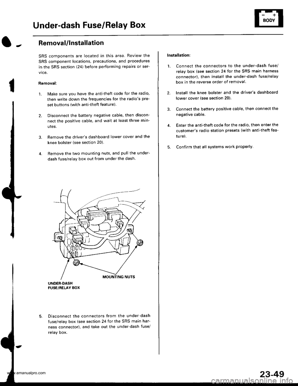
4. Remove the two mounting nuts, and pull the under-
dash fuse/relay box out from under the dash
Disconnect the connectors from the under-dash
fuse/relay box (see section 24 for the SRS main har-
ness connector), and take out the under-dash fuse/
relay oox.
Installation:
1. Connect the connectors to the under-dash fuse/
relay box (see section 24 for the SRS main harness
connector), then install the under-dash lusehelay
box in the reverse order of removal.
2. lnstall the knee bolster and the driver's dashboard
lower cover (see section 20).
3. Connect the battery positive cable, then connect the
negative cable.
4. Enter the anti-theft code for the radio, then enter the
customer's radio station presets (with anti-thett fea-
ture).
5. Confirm that all systems work properly
23-49
www.emanualpro.com
Page 1214 of 1395
lgnition Switch
Test
SRS components are located in this area. Review the
SRS component locations, precautions, and procedures
in the SRS section {24} before performing repairs or ser
vtce.
L lMake sure you have the anti-theft code for the
radio, then write down the frequencies for theradio's preset buttons (wilh anti-theft feature).
2. Disconnect the battery negative cable.
3. Remove the driver's dashboard lower cover and the
knee bolster {see section 20).
4. Disconnect the 5P connector from the under-dash
fuse/relay box and the 3P connector from the main
wtre narness,
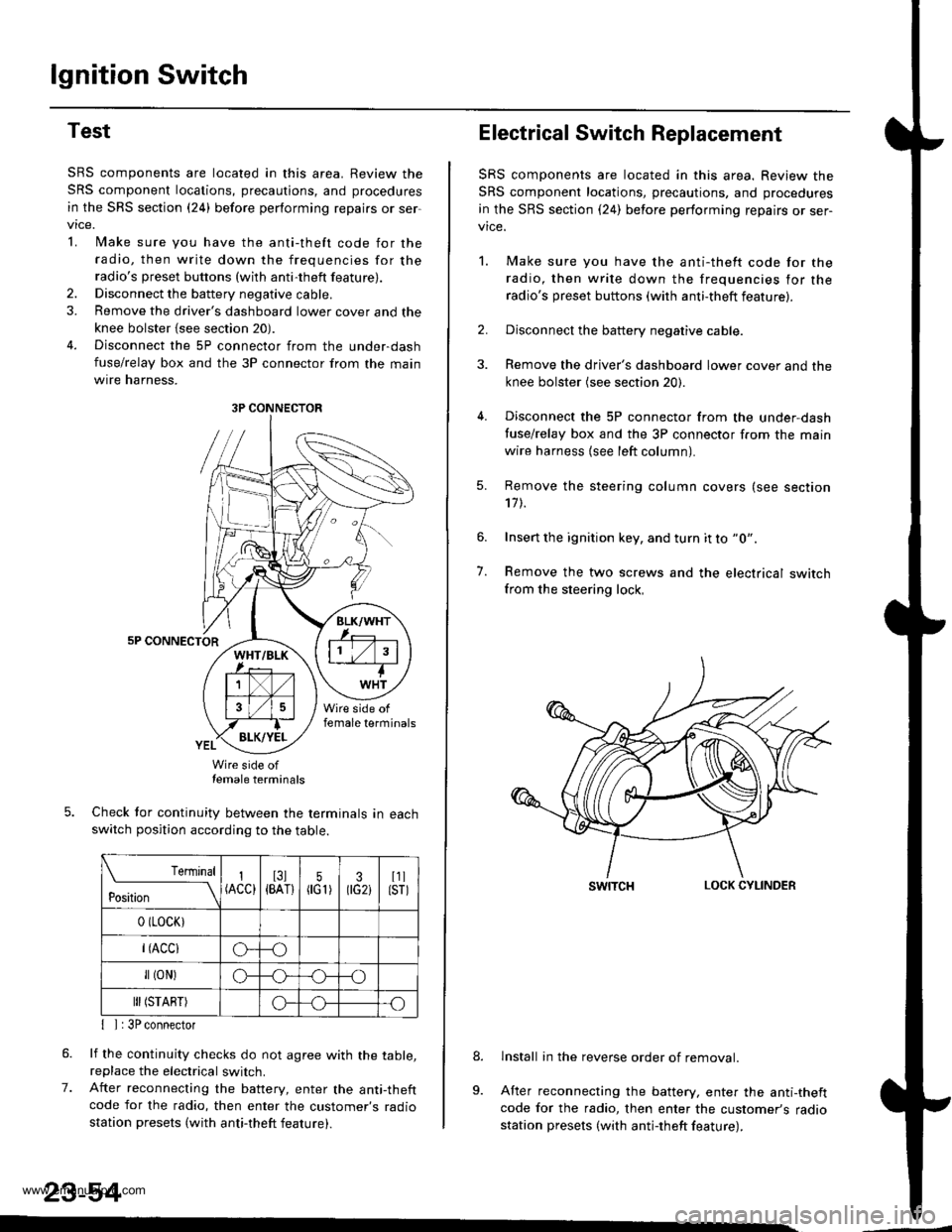
5P CONNECTOR
Wire side oftemale terminals
Check tor continuity between the terminals in eachswitch position according to the table.
rernrnal
ros[ron \
I(ACC)I3l{BAT}5flG1)30G2iI1llsrl
0 (LocK)
r(Acclo--o
fl (oN)G_o
III (START)o--.o
7.
{ I | 3P connector
lf the continuity checks do not agree with the table,replace the electrical switch.
After reconnecting the battery, enter the anti-theftcode for the radio, then enter the customer's radio
station presets (with anti-theft feature).
23-54
3P CONNECTOR
Electrical Switch Replacement
SRS components are located in this area. Review the
SRS component locations, precautions, and procedures
in the SRS section {24) before performing repairs or ser-vice.
1. Make sure you have the anti-thett code for the
radio, then write down the frequencies for the
radio's preset buttons (with anti-theft feature).
2. Disconnect the battery negative cable.
3. Remove the driver's dashboard lower cover and the
knee bolster (see section 20).
4. Disconnect the 5P connector from the under,dash
tuse/relay box and the 3P connector f.om the main
wire harness {see left column).
7.
Remove the steering column covers (see section'17 t.
Insert the ignition key, and turn it to "0".
Remove the two screws and the electrical switchfrom the steering lock,
swrTcHLOCK CYLINDER
lnstall in the reverse order of removal.
After reconnecting the battery, enter the anti-theftcode for the radio, then enter the customer's radiostation presets (with antj-theft feature).
9.
www.emanualpro.com
Page 1262 of 1395
Stereo Sound System
Audio Unit Removal
Make sure you have the anti-theft code for the
radio, then write down the frequencies for the
radio's preset buttons (with anti-theft feature).
Remove the center panel (see section 201,
Remove the four mounting bolts, and pull the audio
unit out.
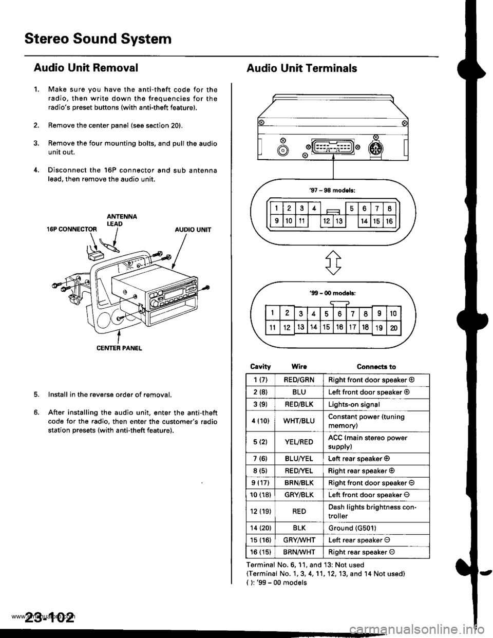
Disconnect the 'l6P connector and sub antenna
lead, then remove the audio unit.
Install in the reverse order of removal.
After installing the audio unit, enter the anti-theft
code for the radio. then enter the customer's radio
station presets (with anti-theft feature).
1.
AUDIO UNIT
CENTEB PANEL
23-102
Audio Unit Terminals
CavrtyWireConnoct3 to
Terminal No.6, 11, and 13: Not used(Terminal No. 1,3, 4,'11,12, 13, and '14 Not us6d)
{ ): '99 - 00 models
1{7)RED/GRNRight front door speaker @
2 {8}BLULeft front door speaker @
3 {9)RED/BLKLights-on signal
4 (10)WHT/BLUConstant power (tuning
memory)
5 (2)YEUREDACC (main sterso power
supplyl
7 (6)BLU/YELLeft rear soeaker @
8 (s)RE D/VELRight rear speaker @
9 (17)BRN/BLKRiqht f.ont door speaker O
10 (18)GRY/BLKLeft front door soeaker O
12 (19)REDDash lights brightness con-
troller
14 (20)BLKGround (G501)
15 (16)GRYMHTLeft rear speaker O
16 (15)BRN^ll/HTRight resr speaker O
www.emanualpro.com
Page 1301 of 1395
JFront Seat Belt RePlacement
SRS components are located in this area. Review the SRS
component locations, precautions, and procedures in this
section (24) before performing repairs or service ('98 - 00
models).
CAUTION: Check the front seat bslts for damago. and
replaco thom if necessary. Be careful not to damage
them during removal and in3tallation'
Front scat bolt:
1. Make sure you have the anti-theft code for the
radio, then write down the frequencies for the pre-
set buttons.
2. Disconnect the negative battery cable, and wait at
least three minutes before beginning work.
3. Slide the front seat forward fully.
4. Bemove (see section 20):
. Center pillar lower trim Pane
. Kick oanel
. Front side trim
5. '97 model: Remove the upper anchor cover and the
lower anchor caP.'98 - oO models: Remove the upper anchor cover
and pull the lower anchor cover back.
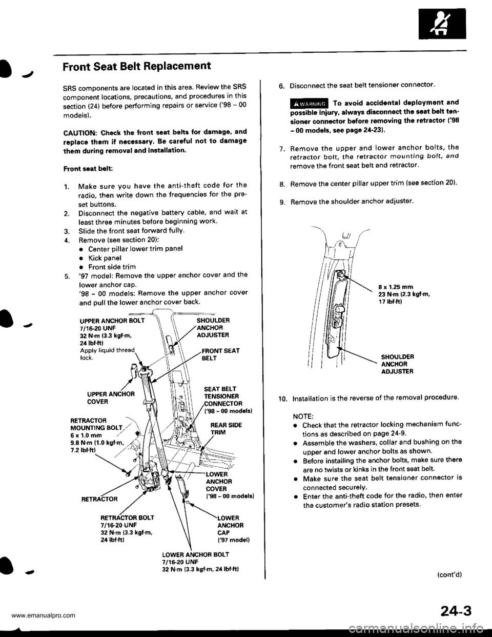
UPPEN ANCHOR BOLT
7/1&20 UNF32 N.m (3.3 kgt'm.24 tbf.ft)
SHOULDERANCHORADJUSTER
Apply liquid threadlock.
9.8 N.m (1.0 kgt.m,?.2 tbtft)
UPPERCOVER
RETRACTORMOUNTING BOLTZ,,Gx1.0mm ./
SEAT BELTTENSIONER
{'98 - 0o modols)
REAR SIDE
ANCHORCOVERl'98 - 00 models)
ANCHORCAP('97 modell
RETRACTOR BOLT7/1&20 UNF32 N.m 13.3 kgt m,24 tbt.ft)
LOWER ANCHOR BOLT?,/1&20 UNF32 N.m {3.3 kgf.m, 2,1 lbf.ftl
o.Disconnect the seat belt tensiongr connector.
@ To avoid accidontal deployment and
possibte inlury, always disconnect the soat bsh ton-
sion€r connoctor bofore rsmoving th6 retractor l'98
- 00 modsls, se€ pa ge 21-231 .
Remove the uDDer and lower anchor boits, the
retractor bolt, the retractor mounting bolt, and
remove the front seat belt and retractor.
Remove the center pillar upper trim (see section 20).
Remove the shoulder anchor adjuster.
7.
9.
8.
I x 1.25 mm23 N.m 12.3 kgt.m,1? tbf.ft)
SHOULDERANCHORADJUSTER
10. lnstallation isthe reverse of the removal procedure.
NOTE:
Check that the retractor locking mechanism func-
tions as described on Page 24-9.
Assemble the washers, collar and bushing on the
uooer and lower anchor bolts as shown.
Eefore installing the anchor bolts, make sure there
are no twists or kinks in the front seat belt.
Make sure the seat belt tensioner connector ls
connected securelv.
Enter the anti-theft code for the radio, then enter
the customer's radio station presets
(cont'd)
24-3
www.emanualpro.com
Page 1324 of 1395
)
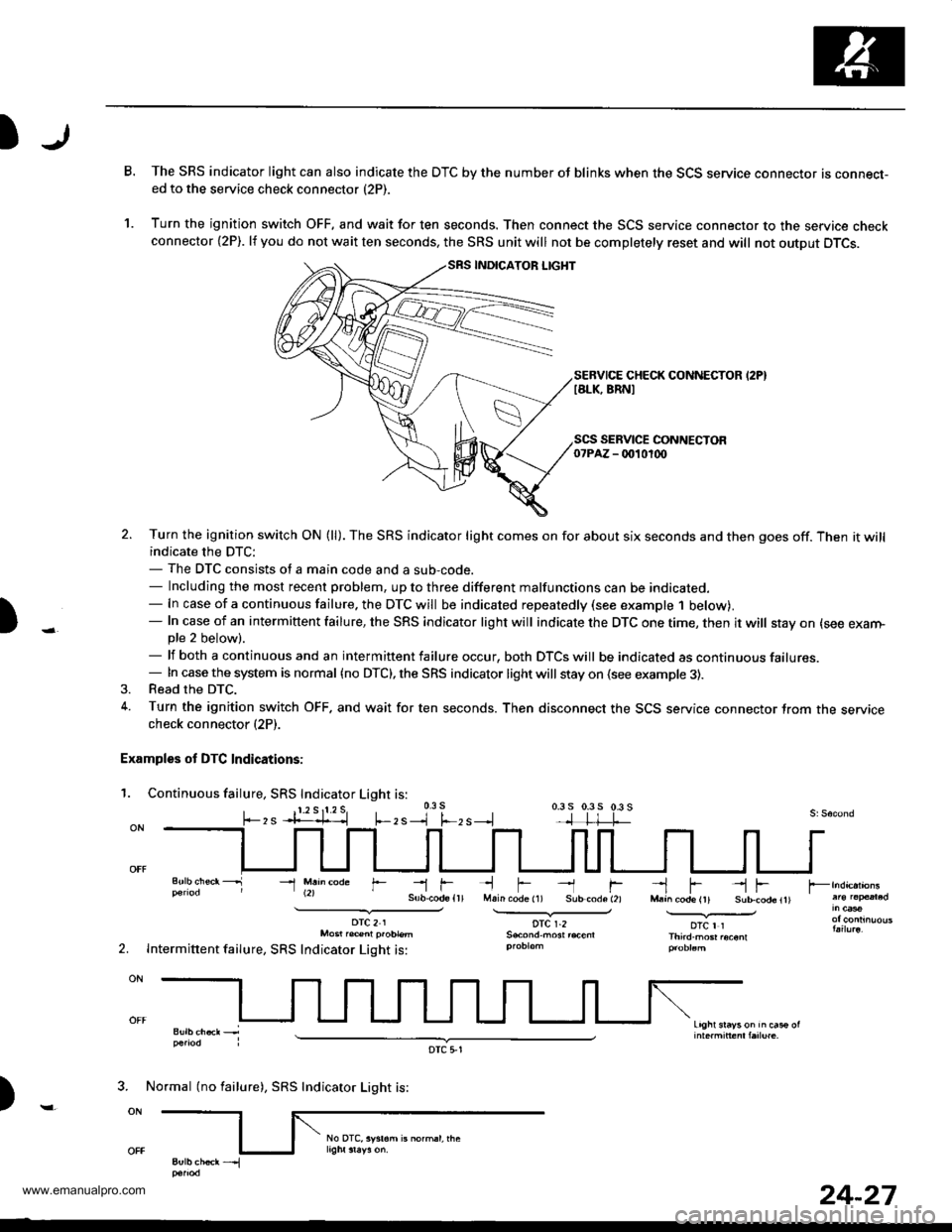
B.The SRS indicator light can also indicate the DTC by the number oJ blinks when the SCS service connector is connecr-ed to the service check connector (2P).
Turn the ignition switch OFF, and wait for ten seconds. Then connect the SCS service connector to the service checkconnector {2P). lf you do not wait ten seconds. the SRS unit will not be completely reset and will not output DTCS.
SEBVICE CHECK CONNECTOR I2PIIALK, BRNI
1.
)
SEBVICE CONNECTOR07PAZ - 0010100
2. Turn the ignition switch ON (ll). The SRS indicator light comes on for about six seconds and then goes off. Then it willindicate the DTC:- The DTC consists of a main code and a sub-code.- Including the most recent problem, up to three different malfunctions can be indicated.- In case of a continuous failure. the DTC will be indicated repeatedly (see example 1 below).- In case of an intermittent failure, the SRS indicator light will indicate the DTC one time, then it will stay on (see exarn-pte 2 below).- lf both a continuous and an intermittent failure occur, both DTCS will be indicated as continuous failures.- In case the system is normal {no DTC), the SRS indicator light will stay on (see example 3).3. Read the DTC.
4. Turn the ignition switch OFF. and wait for ten seconds. Then disconnect the SCS service connector Jrom the servicecheck connector (2P).
Examples of DTC Indications:
1. Continuous failure, SRS Indicator Light is:0.3 s
, s --l f.-, s --.l0.3 s 0.3 5 0.3 s
li-rMain code (1) Sub-code (2)
DTC r.2
--l fl-!
--1 M.h@de r--r f--l F --l FM.a^ code (rt Sub-cod6ltl.............v_otc I rThird.mGr .oconl
Light srayson in cas€ ol
2.
DTC21Mo6t r.@nl p.oblem
Intermittent failure, SRS Indicator Light is:
)
3. Normal (no failure), SRS Indicator Light is:
DTC 5,1
24-27
www.emanualpro.com