shift HONDA CR-V 1997 RD1-RD3 / 1.G Manual Online
[x] Cancel search | Manufacturer: HONDA, Model Year: 1997, Model line: CR-V, Model: HONDA CR-V 1997 RD1-RD3 / 1.GPages: 1395, PDF Size: 35.62 MB
Page 600 of 1395
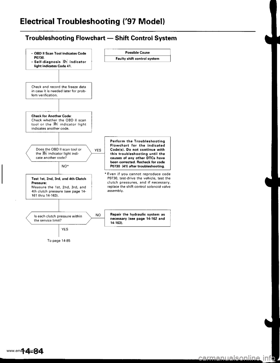
Electrical Troubleshooting ('97 Model)
Troubleshooting Flowchart - Shift Control System
Possible Cause
F""lty "t lft ".tttr"l "y"t..
+ Even it you cannot reproduce codeP0730, test drive the vehicle, test theclutch pressures, and if necessary,replace the shift control solenoid valve
. OBD ll Scan Tool indicates CodeP0730.. Selt-diagnosis E,l indicatorlight indicates Code 41.
Check and record the freeze datain case it is needed later for prob-lem verification.
Check tor Another Code:Check whether the OBD ll scantool or the Pll indicator lightindicates another code,
Pertorm the TroubleshootingFlowchart for the indicatedCodels). Do not conlinu€ withthis troubleshooting until thecauses of anv other DTCS havebeen corrected. Recheck for codeP0730 {41) after troubloshooting.
Does the OBD ll scan tool orthe E indicator light indi-cate another code?
Test lst. 2nd, 3rd. and 4th ClutchPressure:Measure the 1st, 2nd, 3rd, and4th clutch pressure (see page 14-161 thru 14-163).
Repair the hydraulic svstem asnecessary lsee page 1,1-162 andr4-1631.
ls each clutch pressure withinthe service limit?
To page 14-85
www.emanualpro.com
Page 601 of 1395
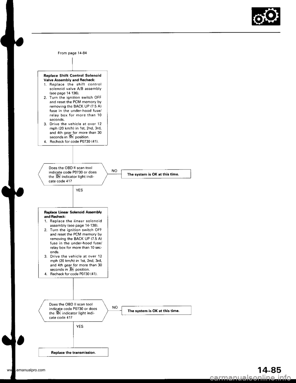
Replace Shift Control Solenoidvslve Assembly and Recheck:1. Replace the shift controlsolenoid valve A/B assembly(see page'14 136).2. Turn the ignition switch OFFand reset the PCM memory byremoving the BACK UP (7.5 A)fuse in the under-hood fuse/relay box for more than 10seconds.3. Drive the vehicle at over 12mph (20 km/h) in 1st,2nd,3rd,and 4th qear for more than 30seconds in E position.
4. Recheck for code P0730 (41).
Does the OBD ll scan toolindicate code P0730 or doesthe E indicator light indicate code 41?
The svstem is OK at this time.
Replace Linea. Solenoid Ass€mblyand Recheck:1. Replace the linear solenoidassembly lsee page 14-138).2. Turn the ignition switch OFFand reset the PcM memory byremoving the BACK UP 17.5 A)fuse in the underhood fuse/relay box tor more than 10 sec'onos.3. Drive the vehicle at over '12
mph {20 km/h) in 1st,2nd,3rd,and 4th geal for more than 30seconds in -Da position.
4. Recheck for code P0730 (41).
Does the OBD llscan toolindicate code P0730 or doesthe Di indicator light indi-cate code 41?
The syslem is OK at this time.
From page 14-84
14-85
www.emanualpro.com
Page 602 of 1395
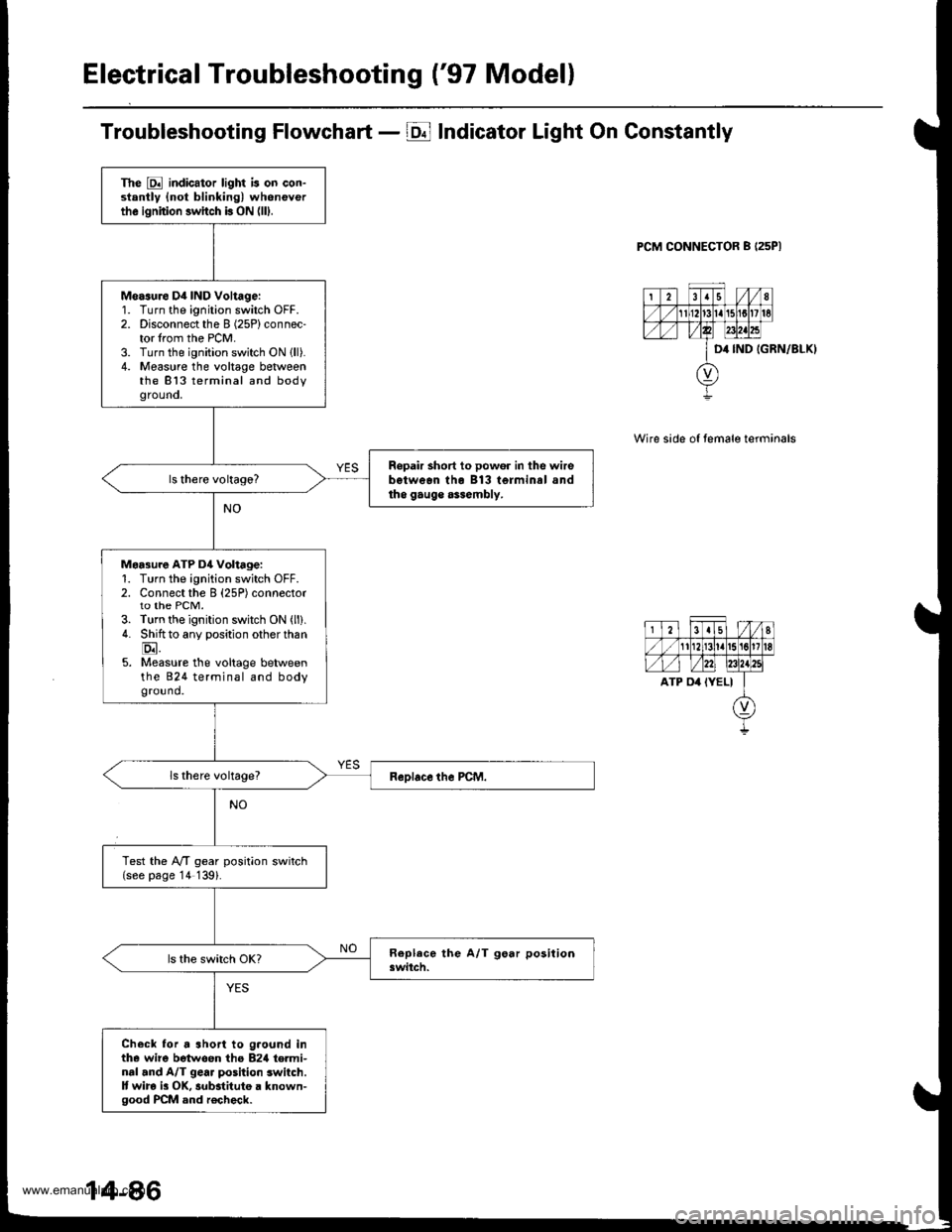
Electrical Troubleshooting ('97 Modell
Troubleshooting Flowchart - E Indicator Light On Constantly
PCM CONNECTOR B I25PI
IGRN/8LKI
Wire side of temale terminals
The E indicator light is on con-stantly {not blinking) wheneverthe ignition switch b ON (lll.
Measure D4 IND Voltage:'1.
2.
3.4.
Turn the ignition switch OFF.Disconnect the I (25P) connec-tor lrom the PCM.Turn the ignition switch ON lll).Measure the voltage betweenthe 813 terminal and bodygrouno,
Ropair short to powor in the wirebetwean tho B13 terminal andtho gauge assembly.
Maa3ure ATP D4 Voltage:1. Turn the ignition switch OFF.2. Connect the B (25P) connectorto the PCM.3. Turn the ignition switch ON (ll).
4. Shiftto any position other than
E.5. Measure the voltage betweenthe 824 terminal and bodyground.
Test the lVT gear position switch(see page '14 139).
Check lor a short to g.ound inthe wire betwoen tho B2rl te.minal and A/T gear position switch.It wira i3 OK, substitute a known-good PCM and r€check.
www.emanualpro.com
Page 603 of 1395
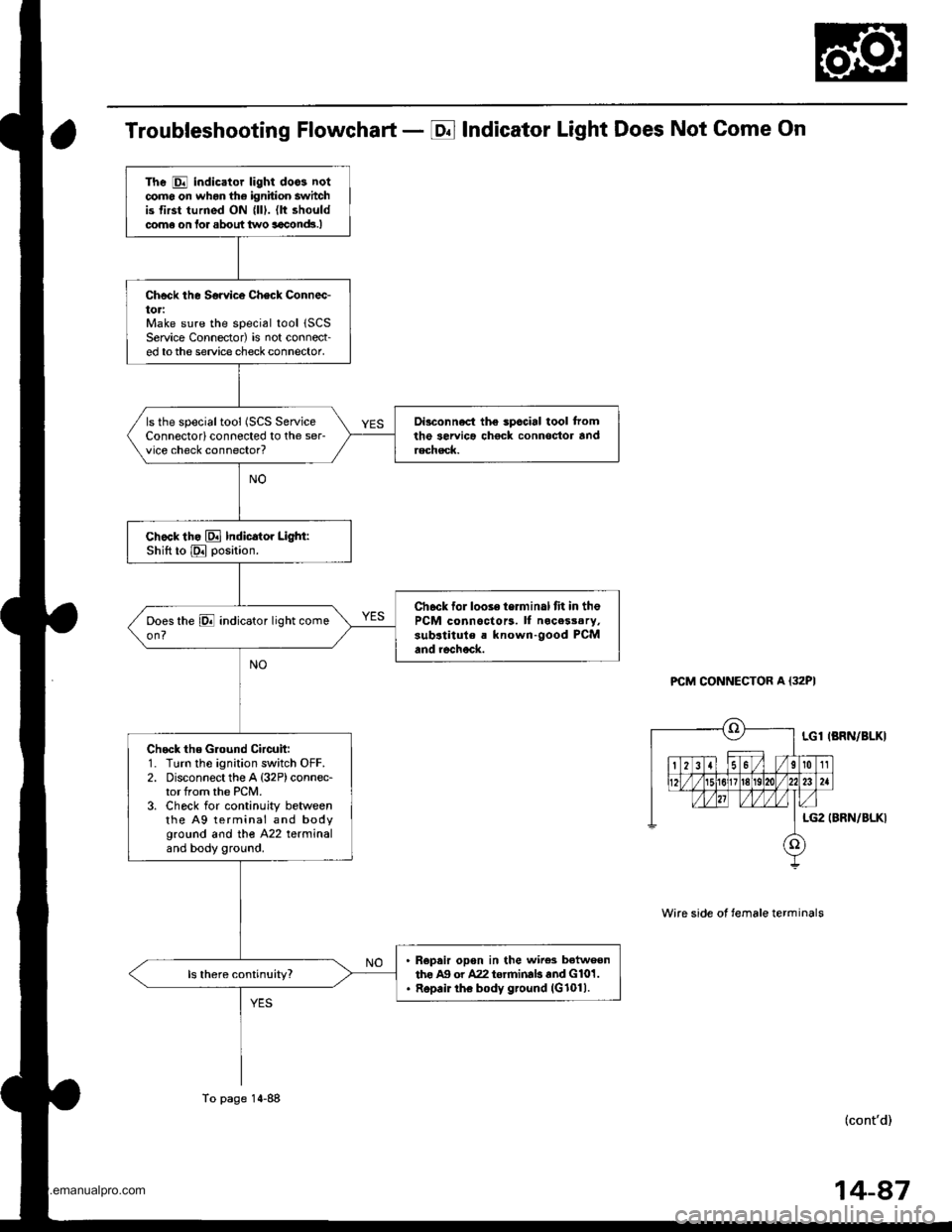
Troubleshooting Flowchart - E Indicator Light Does Not Come On
PCM CONNECTOR A {32PI
Wire side ot temale terminals
LGl IBRN/BLKI
LG2 (BRN/BLKI
(cont'd)
The E indicator light doos notcomo on whon the ignition switchis first turned ON {lll. (lt shouldcome on lor about two aaclnd!.I
Check the Sorvice Check Connec-toriMake sure the special tool 1SCSService Connector) is not connect-ed tothe service check connector,
Di3connect the spccial tool tromthe servica chock connoctor andrechsck.
ls the specialtool (SCS ServiceConnectorlconnected to the ser-vice check connector?
chock th. El Indicator Light:Shift to E position.
Ch6ck for looie terminal fit in thePCM connoctors. ll nocesssry,sub.titule a known-good PCMand rechock.
Check the Ground Circuit:1. Turn the ignition switch OFF.2. Disconnect the A {32P)connec-tor from the PCM.3. Check for continuity betweenthe A9 terminal and bodyground and tho A22 terminaland body ground.
R€pair opon in the wire3 betweenthe Ag or A22 torrninab and G101.Repair the body ground (G1011.
To page 14-88
14-87
www.emanualpro.com
Page 605 of 1395
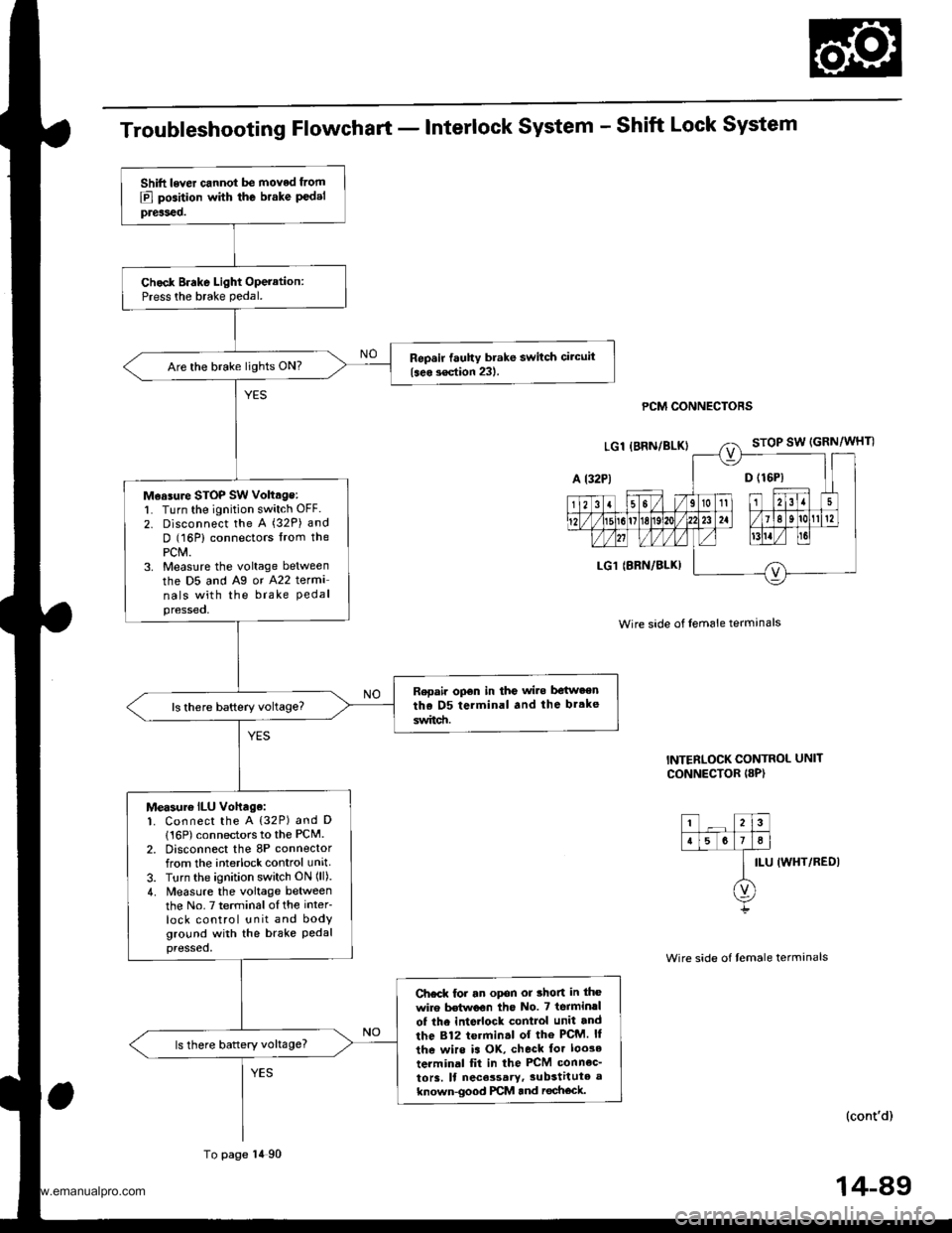
Troubleshooting Flowchart - Interlock System - Shift Lock System
PCM CONNECTORS
Wire side of lem6le termanals
INTERLOCK CONTROL UNIT
CONNECTOR I8P)
ILU IWHT/REDI
(cont'd)
Shift lever cannot be moved from
E] position with the brake P€delpreiseo.
Chock Brake Light Operation:Press the brake pedal.
Repsir fauhy brake switch circuit
{seo s€ction 231.Are the brake lights ON?
M€asure STOP SW voltage:l� Turn the ignition switch OFF.
2. Disconnect the A (32P) and
D (16P) connectors lrom thePCM.3. Measlre the voltage between
the D5 and Ag or A22 terma
nals with the brake Pedalpressed,
Repair opon in the wi.e be{w.enthe D5 terminal and the br.ke
switd!.
Measur€ ILU vohage:1. Connect the A {32P) and D
116P) connectors to the PCM.2. Disconnect the 8P connectorfrom the interlock control unit
3. Turn the ignition switch ON (ll).
4. Measure the voltage betweenthe No.7 terminalofthe inter
lock control unit and bodyground with the brake Pedalpressed,
Ch€ck for an opon or thon in the
wire Mwoon tho No. 7 terminrl
of the inte ock control unit and
the 812 termin.l of the PcM. ll
the wirs is OK, check tor loo3e
terminal fit in the PCM connec_
to13. ll nece3sary,3ubstitute a
known-good PCM and rechock.
ls there battery voltage?
To page 14 90
14-89
www.emanualpro.com
Page 606 of 1395
Electrical Troubleshooting ('97 Model)
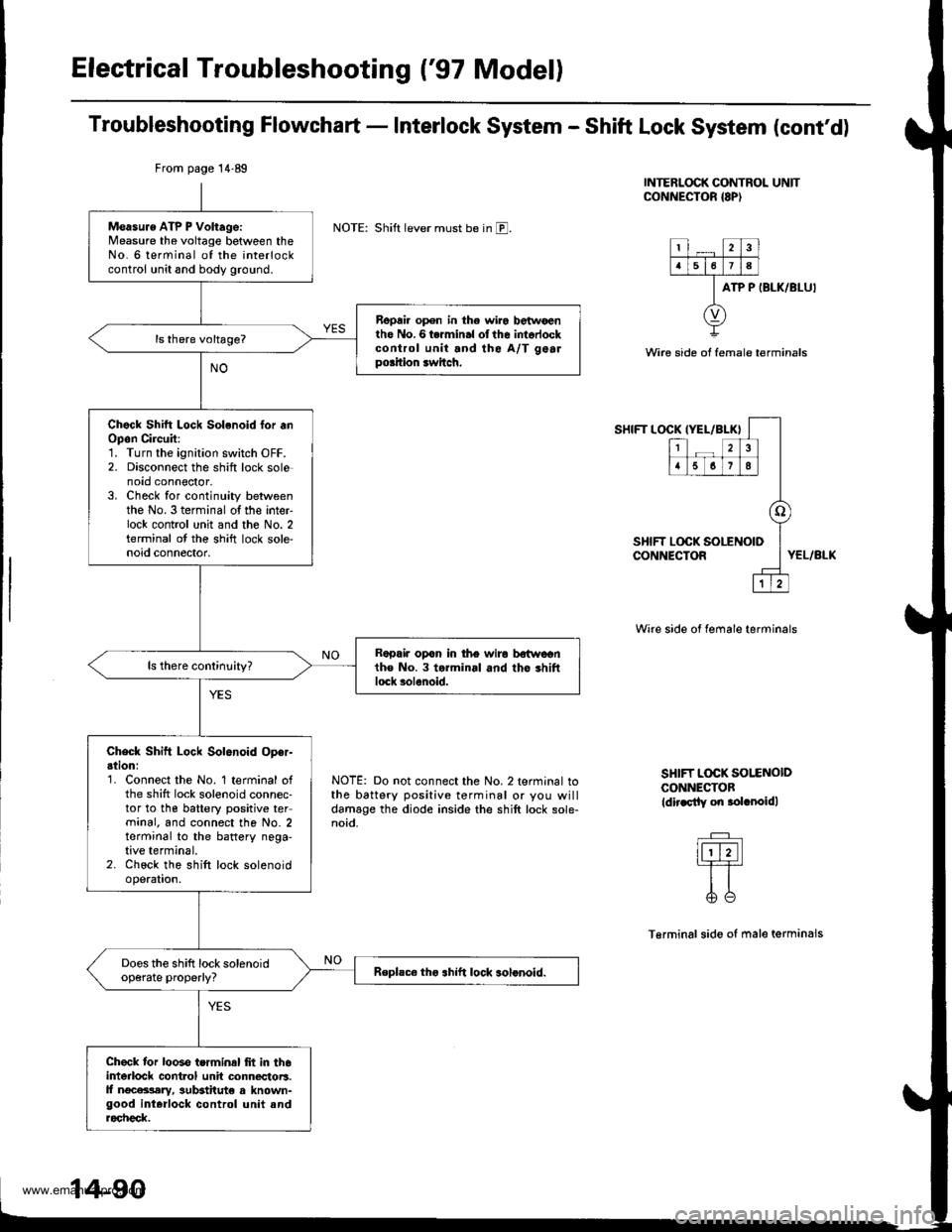
Troubleshooting Flowchart - Interlock System - Shift Lock System (cont'd)
INTERLOCK CONTROL UNITCONNECTOR {8P)
NOTE: Shift lever must be in E.
ATP P IBLK/BLU'
Wire side ot female terminals
SHIFT LOCKIYEL/BLK}
12
5678
o
LOCK SOLENOID
1
SHIFT LOCK !CONNECTORYEL/BLK
NOTE: Do not connect the No. 2 terminal tothe battery positive terminal or you willdamage the diode inside the shift lock sole-noid.
Wire side of female terminals
SHIFT L@K SOI.ENOIDCONNECTOBldir.sily on .olrnoidl
Terminalsido of male terminals
From page 14.89
Measu.e ATP P Voltage:Measure the voltage between theNo. 6 terminal of the interlockcontrol unit and body ground.
Repai. open in the wir6 betwoentho No.6 termin.l olthe intorlockcontrol unit and the A/T gealpo.ition rwitch.
Chock Shitt Lock Solenoid lor .nOpon Circuit:1. Turn the ignition switch OFF.2. Disconnect the shift lock solenoto connoctor.3. Check for continuity betweenthe No. 3 terminal of the inter-lock contrcl unit and the No. 2terminal ot the shift lock sole-noid connector.
Rapair opon in the wiro bstwcentho No. 3 torminal and tho shiftlock solenoid.
Check Shift Lock Solenoid Oper-ation:'1. Connect the No. 1 terminal ofthe shift lock solenoid connec-tor to the battery positive terminal. and connect the No. 2terminal to the battery nega-tive terminal.2. Chock the shift lock solenoidoperation.
Does the shift lock solenoidop€rate properly?Replsc€ tho .hift lock solonoid.
Check tor looso terminal frt in th6interlock cont.ol unit connectoB.ll ngcara,lary, sutEtitut€ a known-good interlock control unit androcheck.
www.emanualpro.com
Page 607 of 1395
![HONDA CR-V 1997 RD1-RD3 / 1.G Manual Online
Troubleshooting Flowchart - Interlock system - Key Interlock system
IGNITION SW]TCH 6P CONNECTOR
KEY LOCK SOL
{WHT/BLU)
ACC PUSH SW (WHT/YELI
Wire side oI female terminals
KEY LOCK SOL(WHT/BLUI
(cont HONDA CR-V 1997 RD1-RD3 / 1.G Manual Online
Troubleshooting Flowchart - Interlock system - Key Interlock system
IGNITION SW]TCH 6P CONNECTOR
KEY LOCK SOL
{WHT/BLU)
ACC PUSH SW (WHT/YELI
Wire side oI female terminals
KEY LOCK SOL(WHT/BLUI
(cont](/img/13/5778/w960_5778-606.png)
Troubleshooting Flowchart - Interlock system - Key Interlock system
IGNITION SW]TCH 6P CONNECTOR
KEY LOCK SOL
{WHT/BLU)
ACC PUSH SW (WHT/YELI
Wire side oI female terminals
KEY LOCK SOL(WHT/BLUI
(cont'd)
lgnition key cannot be moved
Irom ACC (l) pGition to LOCK (0)
position while Pushing the igni-
tion kev with the shift lever in lllposifio;, and the shift lever but-
ton rcleased.
Check Key Interlock Solenoid
Op€ration:1. Disconnect the ignition switch
connector (6P).
2. Connect the No. 4 terminal of
the ignition switch 6P connec-
tor to the battery Positive ter
minal, and connect the No. 3
terminal to the battery nega
tive terminal.3. Check the key interlock sole
noid operation A clicking
so!nd sho!ld be heard.
Faulty koy interlock solenoid.
Replace the ignition key cylinder/
steedng lock as36mbly
Does the key interlock
solenoid operate properly?
Check Key Interlock Switch OPer'
adon:1. Connect the No. 5 terminal of
the ignition switch connector
to the battery Positive termi
nal, and connect the No 3 ter
minal to the baftery negative
termrnal,2. Turn the ignition switch to
ACC (l), then push rt.
3. Check the key interlock sole'
noid operation. A clicking
sound should be heard whilepushing the ignition key.
Faulty key inte.lock switch
Replaco the ignition key cylindor/
stoering lock a3r.mblY.
Does the key interlocksolenoid operate ProPerlY?
To page 14 92
14-91
www.emanualpro.com
Page 608 of 1395
Electrical Troubleshooting {'97 Model)
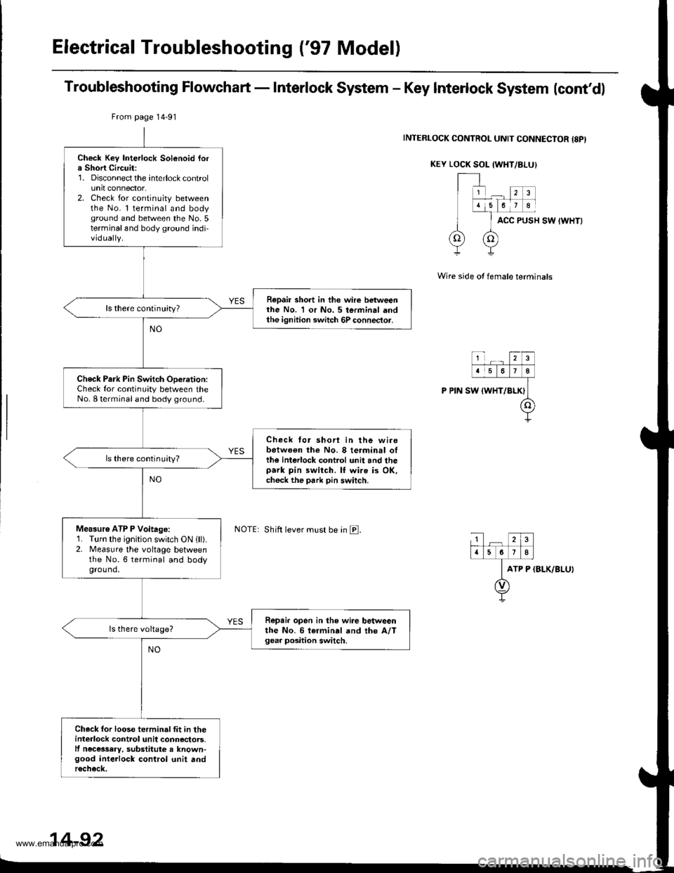
Troubleshooting Flowchart - Interlock System - Key Interlock System lcont'dl
INTERLOCK CONTROL UNIT CONNECIOR {8PI
KEY LOCK SOL {WHT/8I-UI
ACC PUSH SW IWHTI
Wire side of female terminals
ATP P (BLK/BLU)
Check Key Interlock Solenoid fora Short Circuit:1. Disconnect the interlock controlunit connector.2. Check for continuity betweenthe No. l terminal and bodyground and between the No.5terminaland body ground indi-vidually.
Repair short in the wire betweenthe No. 1 or No. 5 terminal andthe ignition switch 6P connector.
ls there continuity?
Check Park Pin Switch ODeration:Check for continuity between theNo. I terminal and body ground.
Check tor shori in the wirebetwo€n the No. 8 terminal otthe interlock control unit and thepark pin switch. lf wire is OK,ch6ck the park pin switch.
ls there continuity?
Measu16 ATP P Voltage:1. Turn the ignition switch ON lll).2. Measure the vohage betweenthe No.6 terminal and bodyground.
R6pei. open in the wire betweenthe No. 6 i€rminal and the A/Tgea. position switch.
Check for loose terminalfit in theinterlock control unil connectors.lf necessery, substitute a known-good interlock control unit andr6check.
From page 14-91
Shift lever must be in E.
14-92
www.emanualpro.com
Page 615 of 1395
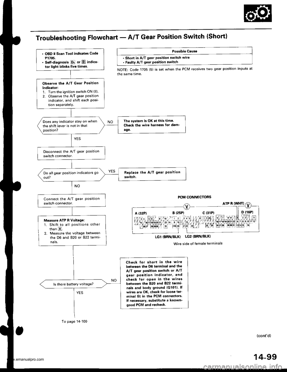
TroubleshootingFfowchart - AIT Gear Position Switch {Short)
Possible Cau3e
. short in A/T gear position switch wire. Faulty A/T gear pGition switch
NOTE: Code 1705 (5) is set when the PCM receives two gear position inputs at
the same time,
PCM CONNECTORS
A (32P1
LGl IBRN/BLK) LG2 (BRN/BLK)
Wire side of female terminals
' O8O ll Scan Tool indicatas Code
P1705.. self-diagnGi3 E or El indica'
tor light blinks five time3
Obs€rve the A/T Goar Position
lndicalor:1. Turn the ignition switch ON (ll).
2. Observe the A/T gear Positionindicator, and shift each Posi'tion seParatelY.
The system is OK at lhis time.
Check the wir€ harne3s fot dam'
age.
Does any indicator stay on when
the shift lever is not in thatposition?
Moasu.e ATP R Voltage:1. Shift to all positions other
than E.2. Measure the voltage between
the D6 and 820 or 822 termi-nals,
Check for short in the wire
betwoon thc DS terminal and tho
A/T gear position switch or A/Tgear porition indicatol, and
check for open in the wires
batween the 820 and 822 t6lmi'
nals and body ground 1G1011. lf
wires are OK, check lor loos€ i€r_
minel fit in the PCM connectors.
lf necBsarv, substittlle a known'good PCM and recheck.
To page'14-100
(cont'd)
14-99
www.emanualpro.com
Page 616 of 1395
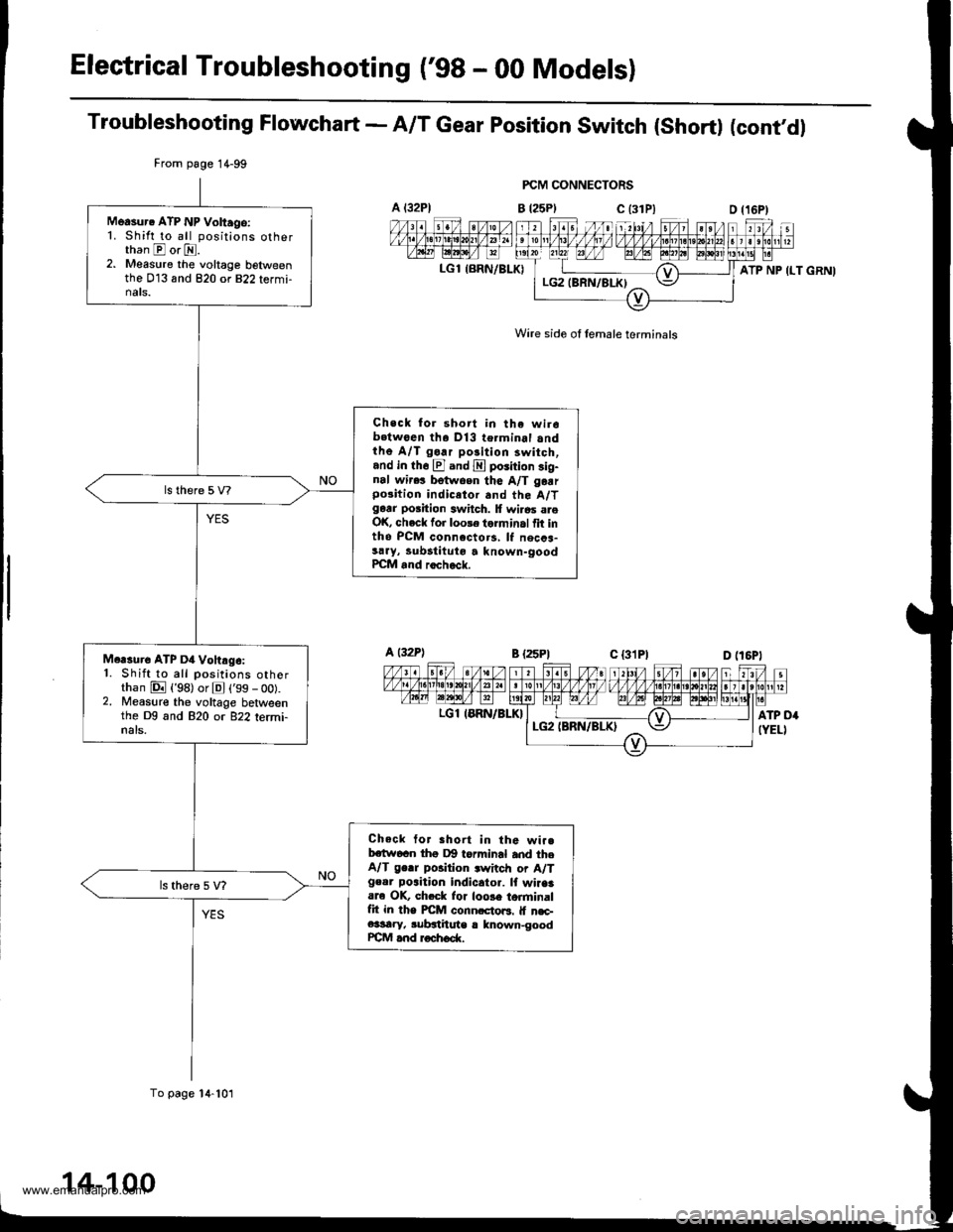
Electrical Troubleshooting ('98 - 00 Modelsl
Troubleshooting Flowchart - A/T Gear position switch (short) (cont'dl
FCM CONNECTORS
B t25Plc (31P)
Wire side of lemale terminals
A t32Pl
LGl {BRN/BLK)
From page 1 4-99
To page 14-101
Measur. ATP NP Voltago:1. Shift to all positions otherthan E or E.2. Measure the voltage belweenthe 013 and 820 or 822 termi-nats.
Check for short in the wir6b.twoen tha Dl3 terminal andthe A/T go.r polition 3witch,and in th6 El and E poiition sig-nal wir.! betwoen the A/T garrpo3ition indicetor and the A/Tgarr position switch. lf wi.6s areOK, check for loole torminal fit intho PCM connccto.s, lf necca-sary, lubstituto a known-goodPCM and rocheck.
Mcrsure ATP D4 Vohrg6:1. Shift to all positions otherthan E {'98) or El ('99 - oo).2. Measure the voltage betweenthe Dg and 820 or 822 termi-nals.
Check tor Bhort in the wi..bctw6cn thg Dg torminal and theA/T ge.r position .witch or A/Tgeor poaition indicator. lf wiaaaare OK, ch.ck lor loose torminalfit in the PICM conn.cto6. lf n€c-e3sary, subgthute r lnown-goodrcM and roch6d(.
ATP NP ILT GRNI
a t32Pl
LGl IERN/BLK}
14-100
www.emanualpro.com