178 HONDA CR-V 1997 RD1-RD3 / 1.G Workshop Manual
[x] Cancel search | Manufacturer: HONDA, Model Year: 1997, Model line: CR-V, Model: HONDA CR-V 1997 RD1-RD3 / 1.GPages: 1395, PDF Size: 35.62 MB
Page 33 of 1395
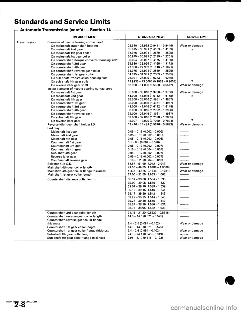
Standards and ServiceLimits
Section 14Automatic Transmission (cont'd)-
MEASUBEMENTSTANDARD {NEW}SERVICE LIMIT
TransmissionDiameter of needle bearing contact areaOn mainshaft stator shaft bearingOn mainshaft 2nd gear
On mainshaft 4th gear collarOn mainshaft 1st gear collarOn countershatt (torque converter housing side)On countershaft 3rd gear
On countershaft 4th gearOn countershaft reverse gear collarOn countershaft 1st gear collarOn sub-shaft {transmission housing sideiOn sub shaft 4th gear collarOn reverse idler gear shaftInside diameter of needle bearing contact areaOn mainshaft 1st gear
On mainshaft 2nd gearOn mainshaft 4th gear
On countershaft 1st gear
On countershaft 3rd gear
On countershaft 4th gear
On countershaft reverse gearOn sub-shaft 4th gear
On reverse idler gearfleverse idler gear shaft holder l.D.End playMainshaft 1st gearMainshaft 2nd gearMainshaft 4th gearCountershaft 1st gearCountershaft 3rd gearCountershaft 4th gear
Sub-shaft 4th gear
Reverse idler gearCountershaft reverse gear
Selector hub O.D.Mainshaft 4th gear collar lengthMainshaft 4th gear collar flange thicknessMainshaft 1st gear collar length
23.980- 23.993 (0.9441 - 0.9446)35.975 35.99'! (1.4163 1.4169)31.975 31.991 (1.2589 1.2595i30.975 - 30.991 11.2195 - 1.2201l'36.004 - 36.017 (1.4175 - 1.4180)35.980 35.996 (1.4165 1.4172)27.980 - 27.993 (1.1016 - 1.1021i31.975- 31.991 (1.2589 -'j.2595i
31.975- 31.991 (1.2589 - 1.2595)25.991 - 26.000 (1.0233 - 1.0236)22.9935 - 23.006s (0.9053 0.9058)13.990 - r4.000 (0.5508 - 0.5512)
35.000 35.016 (1.3780 1.3786)41.000 - 41.016 (1.6142 - 1.6148)38.000 - 38.016 (1.4961 -'1.4967)
38.000 - 38.016 (1.496'1 - 1.4967)41.000 41.016 (1.6142 1.6148)33.000 - 33.016 (1.2992 1.2998)38.000 - 38.016 (1.4961 - 1.4967)32.000 - 32.016 (1.2598 - 1.2605)18.007 - 18.020 (0.7089 - 0.7094)14.416 14.434 (0.5676 0.5683)
0.05 - 0.16 {0.002 - 0.006)0.05 - 0.13 (0.002 - 0.005)0.05,0.'16 (0.002 0.006)0.1 0.5 (0.004 0.020)0.05 0.17 {0.002 0.007)0.10 0.18 (0.004 0.007)0.0s 0.17 (0.002 - 0.007)0.05 - 0.18 (0.002 - 0.007)0.10,0.25(0.004 0.010)51.87 - 51.90 (2.042 - 2.043)49.50 - 49.55 (1.9488 - |.9508)4.435 4.525 (0.1746-0.1781)
27.00,27.05 {1.063'1.065i
Wear or damage
Wear or damage
Wear or damage
Wear or damage
il*=lo'. d"'.n"n"
Wear or damage
Countershaft distance collar length38.97 - 39.00 (1.534 - 1.535)39.02 39.05 (1.536, 1.537)39.07 39.10 (1.538 1.539)39.12 - 39.15 (1.540 - 1.541)39.17 - 39.20 (1.542 * 1.543)39.22 - 39.25 11.544 - 1.545)39.27 39.30 1'1.546 - 1.547i38.87 38.90 {1.530 1.531)38.92 38.95 (1.s32 1.533)
Countershaft 3rd gear collar lengthCountershaft reverse gear collar lengthCountershaft reverse gear collar flangethicknessCountershaft 1st gear collar lengthCountershaft lst gear collar flange thicknessSub-shaft 4th gear collar lengthSub shatt 4th gear collar flange thickness
21.15 - 21.20 rc.4327 - 0.4346)14.5, 14.6 (0.57't , 0.575)
2.4 - 2.6 (0.094 - 0.102)14.5 - 14.6 (0.571 - 0.575)2.4 - 2.6 (0.094 - 0.102)24.0 24.1 (0.945 0.949)2.95 - 3.10 (0.116 - 0.122)
Wear or damage
Wear or damage
Wear or damage
2-8
www.emanualpro.com
Page 204 of 1395
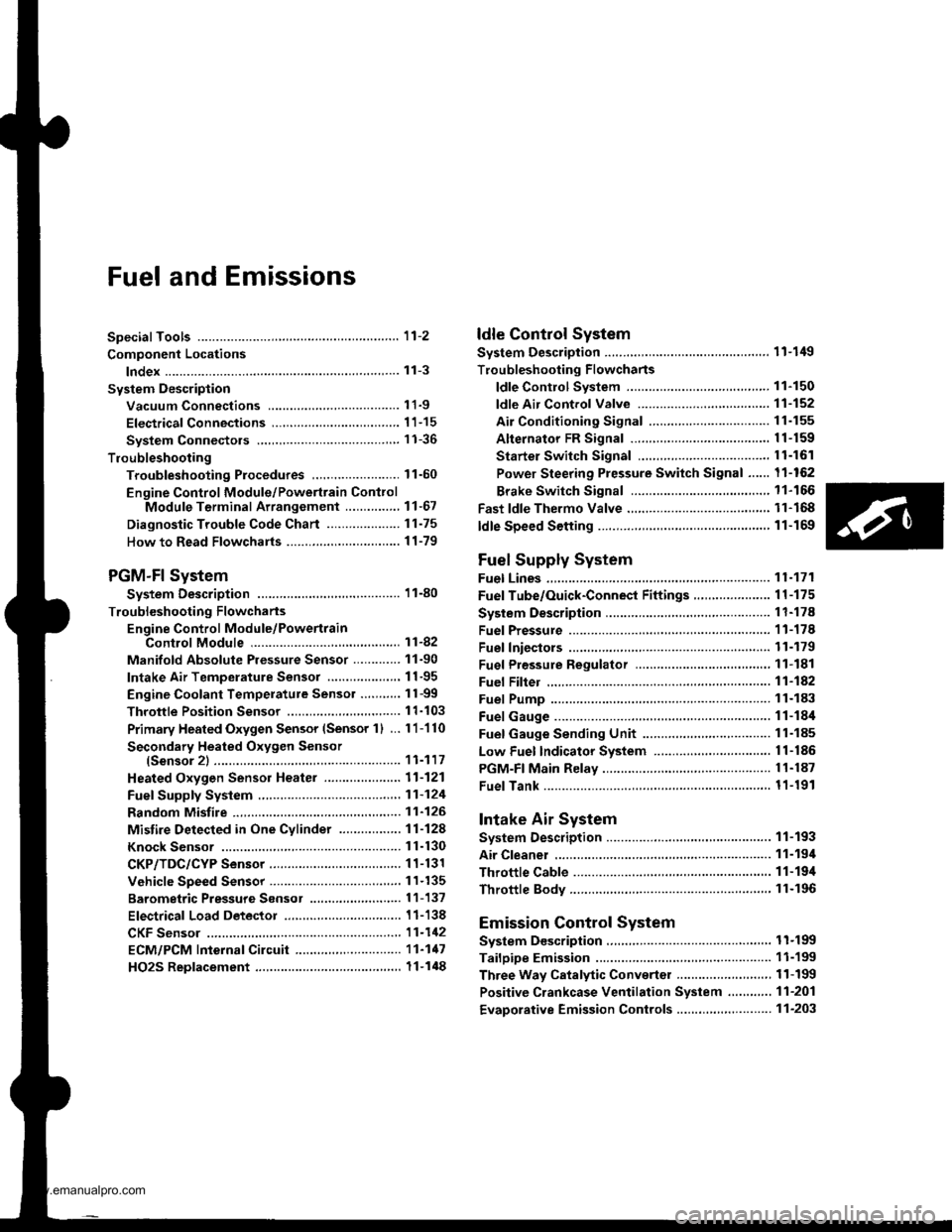
Fuel and Emissions
Special Tools ...................... 11-2
Component Locations
lndex ...................... ....,.... 11-3
Svstem Description
Vacuum Connections ...........,....,.,................. 1 1-9
Electrical Connections ................................... 1 1-15
System Connectors .,.,,.,............................,.,. 1 1-36
Troubleshooting
Troubleshooting Procedures,.,..................... 11-60
Engine Control Module/Powertrain ConttolModule Terminal Arrangement .............., 11-67
Diagnostic Trouble Code Chart .................... 1 t-75
How to Read Flowcharts .......,.....,.,............... I 1-79
PGM-Fl System
System Description .................,.,.,,,............... 1 1-80
Troubleshooting Flowcharts
Engine Control Module/PowertrainControl Module ........11-52
Manifold Absolute Pressure Sensor ............. 11-90
Intake Air Temperature Sensor .................... 1 1-95
Engine Coolant Temperature Sensor .,..,.,.... 1 1-99
Throttle Position Sensor ...........,.....,.,.,..,...... I 1'103
Primary Heated Orygen Sensor (Sensor 1) ... 11-110
Secondary Heated Oxygen Sensor{Sensor 2l .................. 1 1-117
Heated Oxygen Sensor Heater ..................... 11-121
Fuef Supply System ......11-124
Random Misfire ,....,.,..... 11-126
Mistire Detected in One Cylinder .....-........... 11-128
Knock Sensor ................ 11-130
CKP/TDC/CYP Sensor .................................... 1 1-131
Vehicle Speed Sensor ...............................,.... 1 1-135
Barometric Pressure Sensor .....,...,...,.,,........ 1 1-137
Electrical Load Detector ...,.,.......................... 1 1-138
CKF Sensor ................,.,, '11-112
ECM/PCM lnternaf Circuit ............................. 11'117
HO2S Replacement .,.,.,. 11-148
ldle Control System
System Description ............ 11-149
Troubleshooting Flowcharts
ldle Control System ...... 11-150
fdle Air Control Valve ......................,............. 11-152
Air Conditioning Signal ................................. I 1-155
Alternator FR Signal ...................................... 1 1-159
Starter Switch Si9na1 .................................... t l-161
Power Steering Pressure Switch Signal ...... 11-162
Brake Switch Si9na1 ...................................... 11-166
Fast ldle Thermo Valve .,.,.............................,.,.,. 11-168
ldle speed setting .............. 11-169
Fuel Supply System
Fuel Lines ............................ 11-171
Fuef Tube/Ouick-Conneci Fittings ..................... 11 -175
System Description ............ 11-178
Fuel Pressurg ...................... 11-178
Fuel Iniectors ................,..... 11-179
Fuel Pressure Re9u1ator .............................,.,...., f 1-181
Fuef Fifter ....,.,.,.,,,,.,............11-142
Fuel Pump ........................... 11-183
Fuel Gauge .......................... 11-184
Fuel Gauge Sending Unit ................................... I 1-185
Low Fuel Indicator System ...........,.,..,............... 1 1-185
PGM-FI Main Relay ............. 11-187
Fue|Tank................ ............. 11-191
Intake Air System
System Description ............ 11-193
Air Cleanel ,.,.,..................... 11-194
Throttle Cable ..................... 11-194
Throttle Body........ .............. 11-196
Emission Control System
System D$cription ...,....,.,. 11-199
Tailpipe Emission ............... 11-199
Three Way Catalytic Converter ..................,.,...,, 11-199
Positive Crankcase Ventilation System .,.,,,,.,.., 11-2O1
Evaporative Emission Controls .........,.,.,............ 11-203
www.emanualpro.com
Page 205 of 1395
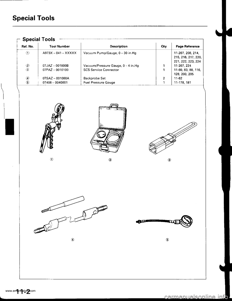
Special Tools
Ref. No. Tool NumberDescriptionOty Page Reference
q
t3'
,3)l
6rl
A973X_041 _XXXXX
07JAZ 0010008
07PAZ , 0010100
07sAz - 001000A
07405 - 0040001
Vacuum Pump/Gauge,0 - 30 in.Hg
Vacuum/Pressure Gauge, 0 4 in.Hg
SCS Service Connector
Backprobe Set
Fuel Pressure Gauge
1
1
2
1
'11-201 . 208,214,
215,2't6,217 ,220,
221 , 222, 223, 224
11 207 , 224
11-60, 83, 88, 1 16,
128,200,205
11-62
11-178, 181
Special Tools
I
11-2
www.emanualpro.com
Page 266 of 1395
Troubleshooting
Troubleshooting Procedures (cont'dl
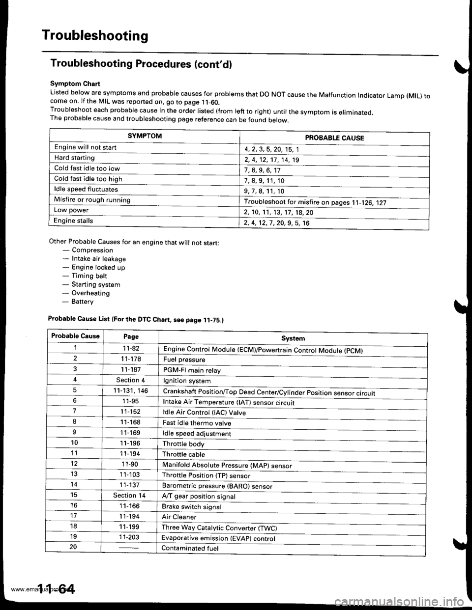
Symptom Chart
Listed below are symptoms and probable causes for problems that DO NOT cause the Malfunction Indicator Lamp (MlL) tocome on. lf the MIL was reported on, go to page 11-60.Troubleshoot each probable cause in the order listed (from left to right) until the symptom is eliminated,The probable cause and troubleshooting page reference can be found below.
Other Probable Causes for an engine that will not start:- Compression- Intake air leakage- Engine locked up- Timing belt- Starting system- Overheating- Battery
SYMPTOMPROBABLE CAUSE
Engine will not sta rt4, 2,3,5,20, 't5, 1
Hard starting2, 4, 12,17, 14, 't9
Cold fast idle too low7, a,9, 6, 17
Cold fast idle too high7,8,9,11,10
ldle speed fluctuates9,7,8, 't1, 10
Misfire or rough runningTroubleshoot for misfire on pages '11-126, 1|21LOl/\/ power2, 10,11, 13, '17, 18,20
Engine stalls2, 4, 12,1,20,9,5, 't6
Probable Cause List (For the DTC Ch8rt, see page ll-75.)
Probable CausePageSystem
Engine controt ruoaute (ecvtffi'I11-42
I 1-178Fuel oressure
PGM-Fl main relav
lgnition system
Crankshatt Position/Top Dead Center/Cylinder position sensor circuit
Intake Air Temperature (lAT) sensor ctrculr
ldle Air Control (lAC) Vatve
Fast idle thermo valve
ldle speed adjustment
Throttle body
Throftle cable
Manifold Absolute P."""rr"ffi
Throftle Position (TP) sensor
Barometric pressur" (gnno-
Ay'T gear position signal
Brake switch signal
Air Cleaner
Three Way Catalytic Converter (TWC)
Evaporative emission (EVAP) control
Contaminated fuel
1 1- 187
Section 4
5't1-'t31,146
6I 't-95
711-152
81'l-168
1 1- 169
1011-196'1111-'194
12'1 'l -90
1 1- 103
1411-137
15Section 14
161 1- 166
17r 1-194
181 1,199'1911-203
20
11-64
www.emanualpro.com
Page 312 of 1395
PGM-FI System
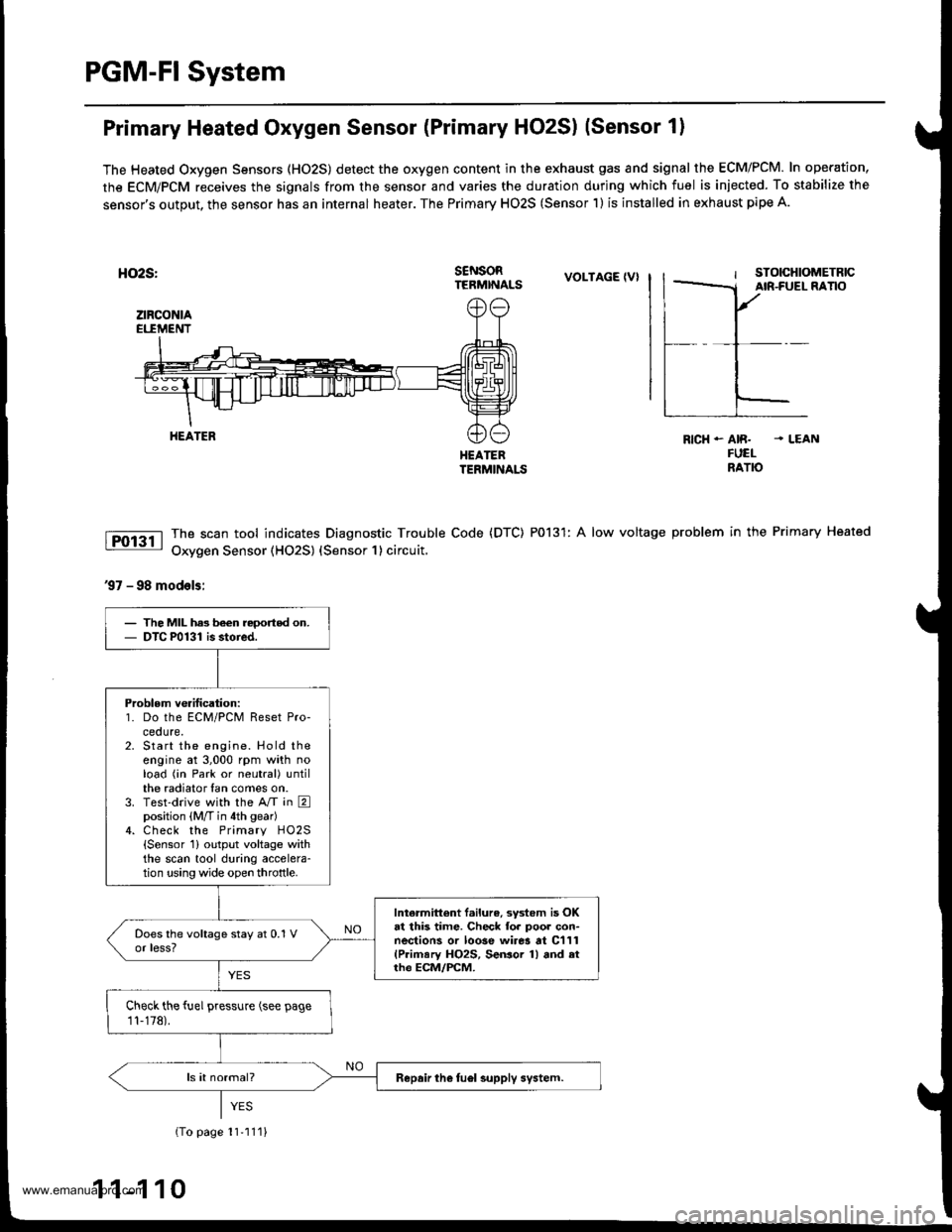
Primary Heated Oxygen Sensor (Primary HO2S) (Sensor 1)
The Heated Oxygen Sensors (HO2S) detect the oxygen content in the exhaust gas and signal the ECM/PCM. In operation,
the ECM/PCM receives the signals from the sensor and varies the duration during which fuel is iniected. To stabilize the
sensor's output, the sensor has an internal heater. The Primary HO2S (Sensor 1) is installed in exhaust pipe A.
HO2S:
ztRcoNtAEI.IMENT
s€NsoRTERMINALSVOLTAGE IVI
HEATEBTERMINALS
The scan tool indicates Diagnostic Trouble Code (DTC) P0131: A low voltage
Oxygen Sensor (HO2S) {Sensor 1} circuit,
RICH - AIR. . LEANFUELNATO
problem in the Primary Heated
37 - 98 models:
HEATER
The MIL has been reoorted on.DTC P0131 is stoied.
Problem verification:1. Do the ECM/PCM Reset Pro-ceoure.Start the engine. Hold theengine at 3,000 rpm with noload (in Park or neutral) untilthe radiator fan comes on.Test-drive with the A/T in Eposition (M/T in 4th gear)Check the Primary HO2S{Sensor 1} output voltage withthe scan tool during accelera-tion using wide open throttle.
Intermittent f.ilure, system is OKat this time. Check fo. poor con-nections or loose wirer at C111(Primary HO2S, SeGor 1) and atrh€ ECM/FCM.
Check the fuel pressure (see page
11-178).
Repair the fuel supply system.
{To page 11'111}
1 1-1 10
www.emanualpro.com
Page 314 of 1395
PGM-FI System
'99 - 00 models:
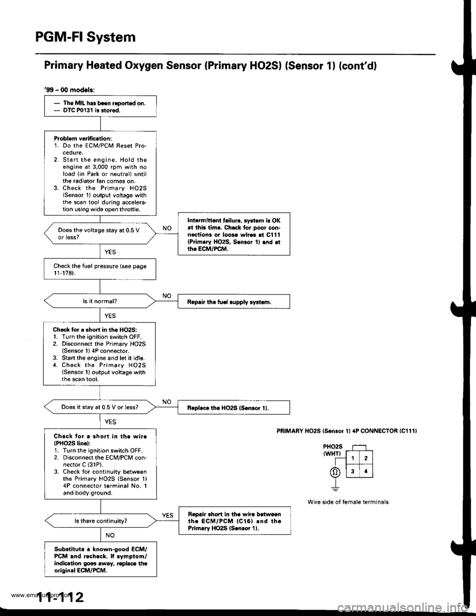
- The MIL has bsen reported on.- DTC P0131 ir storod.
Problem ve fication:1. Do the ECM/PCM Reset Pro-cedure,2. Start the engine. Hold theengine at 3,000 rpm with noload {in Park or neutral) untillhe radiator tan comes on.3. Check the Primary HO2S(Sensor 1) oltput voltage withthe scan tool during accelera-tion using wide op€n throttle.
Inl.rmittant failura, 3yrtam i! OKat thb tim.. Ch.ck tor poor con-nectiona oa looaa wlraa al C111{Pri|n.ry HO2S, Son3or 1l .nd .ttho ECM/FCM,
Does the voltage stay at 0.5 Vor less?
Check tho fuel pressure (see pago1r,178).
R.p.ir th. fu€l lupply ry!t.m.
Chock lor a short in tho HO2S:1. Turn the ignition switch OFF.2. Disconnect the Primary HO2S(Sensor 1) 4P connector.3. St6rt the engine and lot it idle.4. Check the Primary HO2S(Sensor 1) output voltage withthe scan tool,
Does it stay 6t 0.5 V or less?Rephc. th6 HO2S (S.n3or 11.
Chock for a short in tho wirc(PHO2S lino):1. Turn the ignition switch OFF.2. Disconnect the ECM/PCM con-nector C (31P).
3. Check tor continlity betweenthe Primary HO2S {Sensor 'l}
4P connector terminal No. Iand body ground.
Ragah rhort in tha wira balwoanth. ECM/PCM {Cl61 rnd thcPrirn.ry HO2S (S.n3or 11.
Substltut6 a known-good ECM/PCM and recheck. lf rymptom/indicrtion 00os away, raplaco thcoriginal ECM/PCM.
Primary Heated Oxygen Sensor (Primary HO2SI (Sensor 1l (cont'd)
PRIMARY HO2S (Son.or 1l aP CONNECTOR |C111)
PHO2S T--1rwHTr f-T---]
--1 1 2lI t--- 1t6)lslrlv L__r__J
_L
Wire side ol female terminals
11-112
www.emanualpro.com
Page 328 of 1395
PGM-FI System
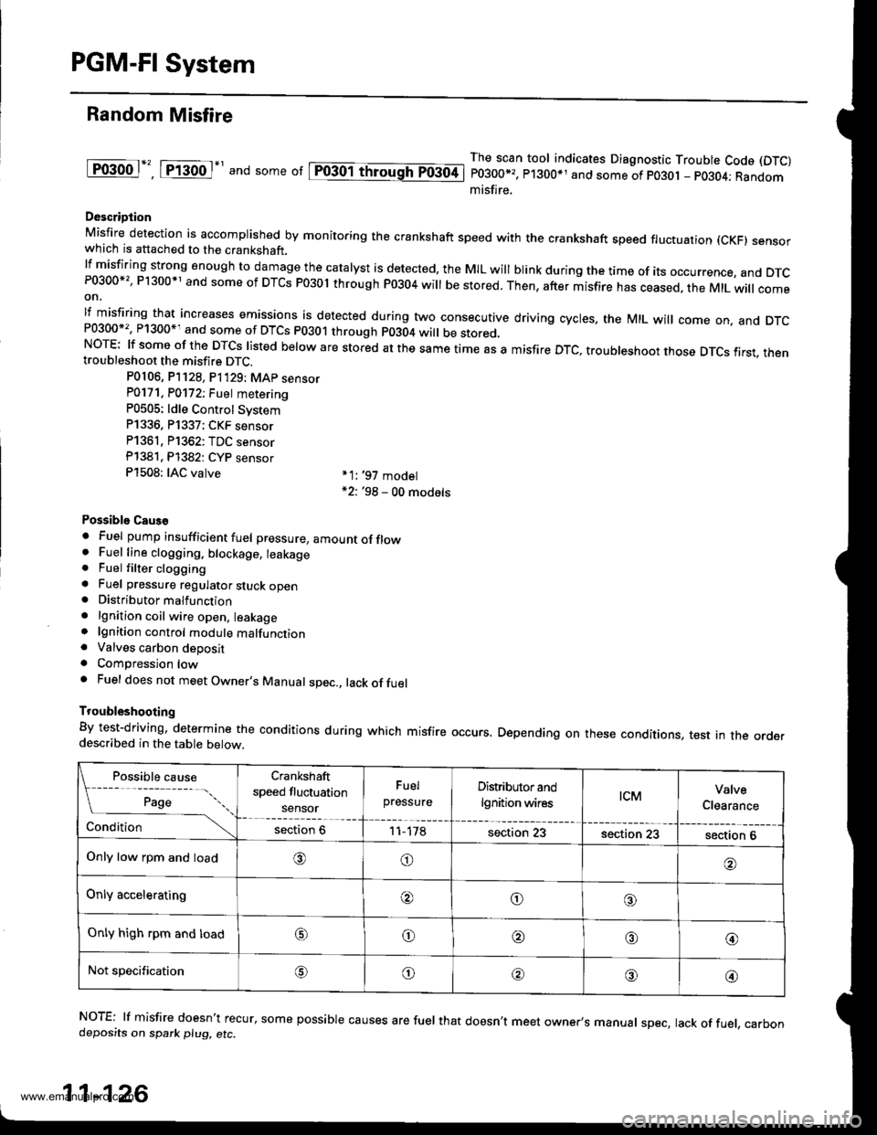
Random Misfire
lF()gool", tftod-' and some or lpiogol throughTo3oti
The scan tool indicates Diagnostic Trouble Code (DTC)
P0300*,, P1300*1 and some of po30t - pO3O4; Randommisfire.
Descriotion
Misfire detection is accomplished by monitoring the crankshaft speed with the crankshaft speed fluctuation (cKF) sensorwhich is attached to the crankshaft.lfmisfiring strong enough to damage the catalyst is detected, the MIL will blink during the time of its occurrence, and DTcP0300*', P1300*1 and some of DTCs P03ol through P0304 will be stored. Then, after misfire has ceased, the MtL will comeon,
lf misfiring that increases emissions is detected during two consecutive driving cycles, the MIL will come on, and DTcand some of DTCS p0301 through p0304 wi
be stored.NOTE: lf some of the DTCS listed below are stored at the same time as a misfire DTc, troubleshoot those DTcs first. thentroubleshoot the misfire DTC.
P0106, P]128, P1'129; MAp sensorP0171. P0172; Fuet metering
P0505: ldle Control Svstem
P1336, P1337; CKF sensor
P1361, P1362: TDC sensor
Pl381. Pl382: CYP sensor
P1508: IAC valve *1:,97 model*2: '98 - 00 models
Possiblo Caus€
. Fuel pump insufficient fuel pressure, amountofflow. Fuel line clogging. blockage, leakage. Fuel filter clogginga Fuel pressure regulator stuck open. Distributormalfunction
. lgnition coil wire open, leakage. lgnition control module malfunction. Valves carbon deposita Compression lowa Fuel does not meet Owner's Manual spec., lack offuel
Troubleshooting
By test-driving, determine the conditions during which misfire occurs. Depending on these conditions, test in the orderdescribed in the table below.
Possible cause
[ ;;;;- -....
Crankshaft
speed fluctuation
sensor
Fuel
pressureDistributor and
lgnition wirestcMValve
Clearance
Conditionsection 611-178section 23section 23section 6
Only low rpm and load,6)o
Only acceleratingooo
Only high rpm and loado@,a'@
Not specificationG\o@o@
NOTE: lf misfire doesn't recur, some possible causes are fuel that doesn't meet owner's manual spec, lack of fuel, carbondeposits on spark plu9, etc.
11-126
www.emanualpro.com
Page 377 of 1395
Fuel Tube/Ouick-Gonnect Fittings
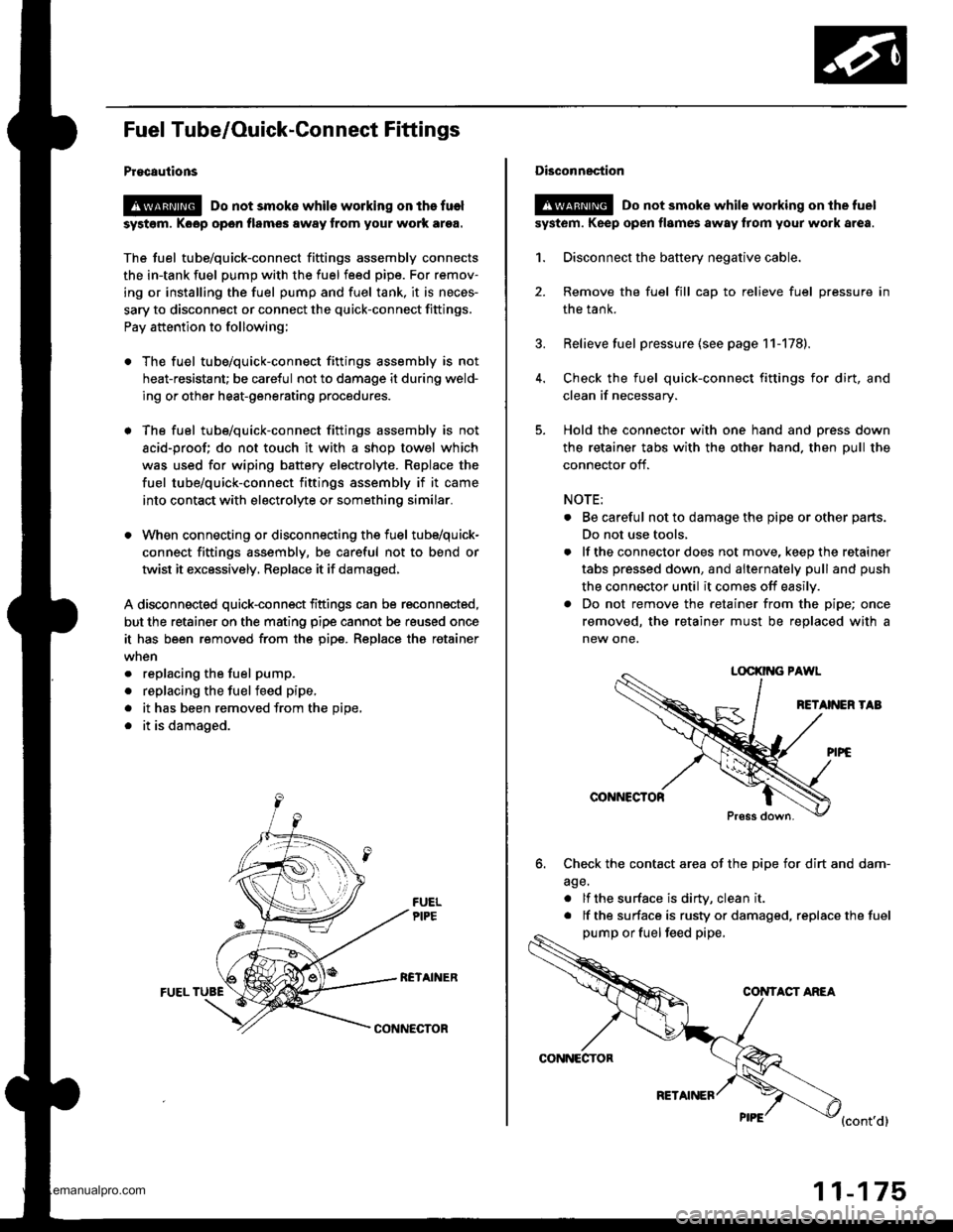
Procautions
@ Do not smoke whils working on the fuel
syst6m, Koop open flames away from your work ar9a.
The fuel tube/quick-connect fittings assembly connects
the in-tank fuel pump with the fuel feed pipe. For remov-
ing or installing the fuel pump and fuel tank, it is neces-
sary to disconnect or connect the quick-connect fittings.
Pay attention to following;
. The fuel tube/quick-connect fittings assembly is not
heat-resistant; be careful not to damage it during weld-
ing or other heat-generating procedures.
. The fuel tube/quick-connect fittings assembly is not
acid-proof; do not touch it with a shop towel which
was used for wiping battery electrolyte. R€place the
fuel tube/quick-connect fittings assembly if it came
into contact with electrolyte or somethino similar.
. When connecting or disconnecting the fuel tube/quick-
connect fittings assembly, be careful not to bend or
twist it excessively, Replace it if damaged,
A disconnected quick-connect fittings can be reconnected,
but the retainer on the mating pipe cannot be reused once
it has been removed from the pipe. Replace tha retainer
. replacing the fuel pump.
. replacing the fuelfeed pipe,
. it has been removed from the Dioe,
. it is damaged.
RCTAINERFUEL TUBE
CONNECTOR
CONNECTOR
RETAINER
11-175
Disconnection
!@ Do not smoke while working on the fuel
syst6m. Keep open flames away from your work area.
1. Disconnect the battery negative cable.
2. Remove the fuel fill cap to relieve fuel pressure in
the tank.
3. Relieve fuel pressure (see page 11-178).
4. Check the fuel quick-connect fittings for dirt, and
clean if necessary.
5. Hold the connector with one hand and press down
the retainer tabs with the other hand. then pull the
connector off.
NOTE:
. Be careful not to damage the pipe or other parts.
Do not use tools,
. lf the connector does not move, keep the retainer
tabs pressed down, and alternately pull and push
the connector until it comes off easily.
. Do not remove the retainer from the pipe; once
removed, the retainer must be replaced with a
new one.
LOCKII{G PAWL
RETANEN TAB
@NNCCTOR
Press down.
6. Check the contact area of the pipe for dirt and dam-
age.
. lf the surface is dirW, clean it
. lf the surface is rusty or damaged, replace the fuel
pump or fuel feed pipe,
CONTACT ANEA
{cont'd}
www.emanualpro.com
Page 380 of 1395
Fuel Supply System
System Description
The fuel supply system consists of a fuel tank, in-tank
high-pressure fuel pump. PGM-Fl main relay, fuel filter,
fuel pressure regulator, fuel injectors, and fuel delivery
and return lines. This system delivers pressure-regulat-
ed fuel to the fuel injectors and cuts the fuel delivery
when the engine is not running.
Fuel Pressure
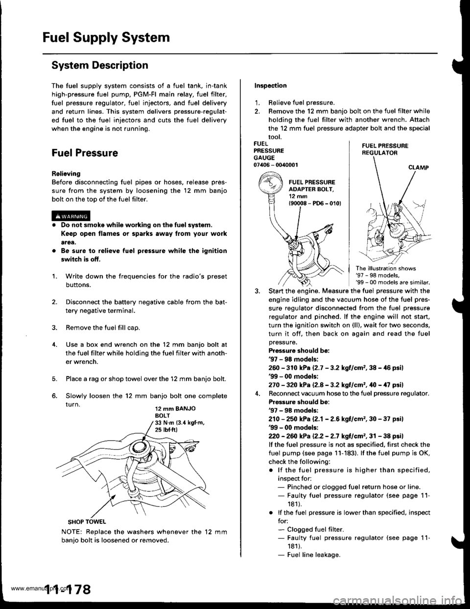
Relieving
Before disconnecting fuel pipes or hoses, release pres-
sure from the system by loosening the 12 mm banjo
bolt on the too of the fuel filter.
Do not smoke while working on the fuel system.
Ke€p open flames or sparks away from your work
area,
Be sure to relieve fuel pressure while the ignition
switch is off.
Write down the frequencies for the radio's preset
buttons.
Disconnect the battery negative cable from the bat-
tery negative terminal.
Remove the fuel fill cap.
Use a box end wrench on the 12 mm banjo bolt at
the fuel filter while holding the fuel filter with anoth-
er wrench.
Place a rag or shop towel over the '12 mm banjo bolt.
Slowly loosen the 12 mm banjo bolt one complete
rurn 12 mm BANJoBOLT
1.
SHOP TOWEL
NOTE: Replace the washers whenever the 12 mm
banio bolt is loosened or removed.
11-178
Inspection
1, Relieve fuel pressure.
2. Remove the 12 mm banjo bolt on the fuel filter while
holding the fuel filter with another wrench. Attach
the 12 mm fuel pressure adapter bolt and the special
tool.
FUEL PRESSUREREGULATON
FUELPRESSUREGAUGE07406 - 0040001
The illustration shows'97 - 98 models,'99 - 00 models are similar.
Start the engine. Measure the fuel pressure with the
engine idling and the vacuum hose of the fuel pres-
sure regulator disconnected from the fuel pressure
regulator and pinched. lf the engine will not start,
turn the ignition switch on (ll), wait for two seconds,
turn it off, then back on again and read the fuel
pressure.
Pressure should be:'97 - 98 mod€ls:
260 -31O kPa 12.7 - 3.2 kgf/cm,, 38 - 46 psil'99 - 0O models:
270 - 32O kPa Q.A - 3.2 kgf/cm', ifo - /U psil
Reconnect vacuum hose to the fuel pressure regulator.
Prgs3ure should be:'97 - 98 models:
210 - 25O kPa 12.1- 2.6 kgf/cm', 30 - 37 psi)'99 - 00 models:
22O -26iJ kPa 12.2 - 2.7 kgt/cm', 31 - 38 psi)
lf the fuel pressure is not as specified, first check the
fuel pump (see page 11- 183). lf the fuel pump is OK,
check the following:
. lf the fuel pressure is higher than specified,
inspect for:- Pinched or clogged fuel return hose or line.- Faulty fuel pressure regulator (see page 11-
181).
. lf the fuel pressure is lower than specified. inspect
for:- Clogged fuel filter.- Faulty fuel pressure regulator (see page 11-
1811.- Fuel line leakage.
www.emanualpro.com
Page 381 of 1395
Fuel Injectors
R6placomoni
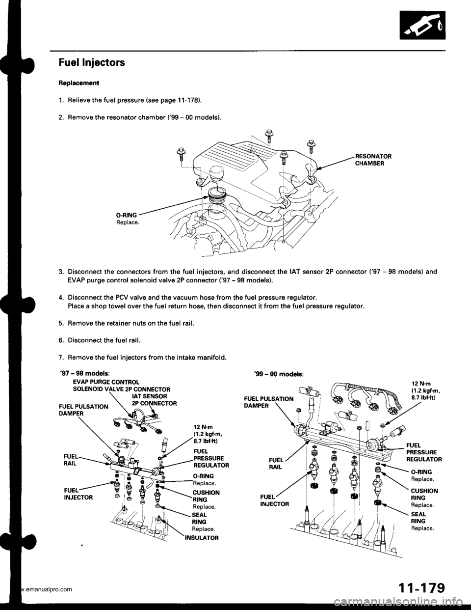
1. Relieve the fuel pressure (see page 11-178).
2. Remove the resonato. chamber ('99 - 00 models).
O.RINGBeplace.
Disconnect the connectors from the fuel injectors, and disconnect the IAT sensor 2P connector ('97 - 98 models) and
EVAP purge control solenoid valve 2P conn€ctor ('97 - 98 models),
Disconnect the PCV valve and the vacuum hose from the fuel pressure regulator.
Place a shop towel over the fuel return hose, then disconnect it from the fuel pressure regulator.
Remove the retainer nuts on the fuel rail.
Disconnect the fuel rail.
7, Remove the fuel injectors from the intake manifold.
'97 - 98 model3:
EVAP PURGE CONTROLSOLENOID VALVE 2P CONNECTORIAT SENSOR
FUEL PULSATION2P CONNECTOR
12 N.m{1.2 kgt'm,8.7 tbtft)
FUELPRESSUREREGULATOR
O.RING
FUELPRESSUREREGULATOR
CUSHION
O.RINGReplace.
CUSHIONRINGReplace.
SEALRINGReplace.
Replace.
SEALRINGReplace.
S
11-179
www.emanualpro.com