stop start HONDA CR-V 1997 RD1-RD3 / 1.G Workshop Manual
[x] Cancel search | Manufacturer: HONDA, Model Year: 1997, Model line: CR-V, Model: HONDA CR-V 1997 RD1-RD3 / 1.GPages: 1395, PDF Size: 35.62 MB
Page 177 of 1395
Oil Pressure SwitchOil Pressure
Testing
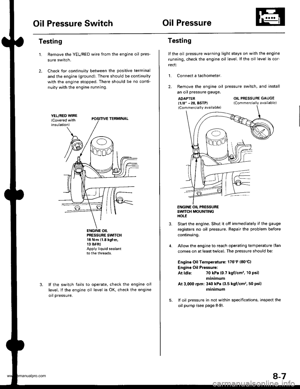
Remove the YEL/RED wire from the engine oil pres-
sure swrtcn.
Check for continuity between the positive terminal
and the engine {ground). There should be continuity
with the engine stopped. There should be no conti-
nuity with the engine running.
L
PRESSURE SWTCH18 N.m {1.8 kgf.m,13 tbr.ftlApply liquid sealantto the threads,
lf the switch fails
level. lf the engine
orl pressure.
to operate, check the engine oil
oil level is OK, check the engine
Testing
lf the oil pressure warning light stays on with the engine
running, check the engine oil level. lf the oil level is cor-
rect:
L Connect a tachometer.
2. Remove the engine oil
an oil pressure gauge.
ADAPTER(1/8" - 28, BSTP)(Commercially available)
pressure switch. and install
OIL PRESSURE GAUGE
{Commercially available)
4.
ENGINE OIL PRESSURESWTTCH MOUNNNGHOt-E
Start the engine. Shut it off immedjately if the gauge
registers no oil pressure. Repair the problem before
continuing.
Allow the engine to reach operating temperature (fan
comes on at least twice). The pressure should be:
Engino Oil Temperature: 176'F (80'C)
Engine Oil Pressure:
At ldle:70 kPa (0.7 kgt/cm'�, 10 psil
minimum
Ai 3,000 rpm: 3/r0 kPa {3.5 kgt/cm', 50 psi)
minimum
lf oil pressure in not within specifications, inspect the
oil pump (see page 8-9).
8-7
www.emanualpro.com
Page 273 of 1395

Engine/Powertrain Control Module Terminal Arrangement - 38 - 00 Models
ECM/PCM CONNECTOR A (32P}
,/./5aIsca
,/ l,/t5ItsTs
n2ls!uCI
Wire side ot female terminalsECM/FCM CONNECTOR A {32P)NOTE: Standard baftery voltage is '12 V.
D93criptionSignal
3BLU2WBS {EVAP BYPASSSOLENOID VALVE)Drives EVAP bvoass solonoid valve.With ignirion switch ON {ll)r battery voltage
LT GRNMHTVSV {EVAP CONTROL CANISTEB VENT SHUT VALVE)D.ives EVAP controlcanisler vent shutWith ig^ition switch ON (ll): battery voltage
5',BLUCRS (CRUISE CONTROL SIG'NAL)Shift Oown signalinputfrcm cruise conWhen cruise control is used: pulses
6RED/YEL
PCS (EVAP PURGE CONTROLSOLENOID VALVE)Drives EVAP purge controlsolonoid valve.With engins running, engine coolant, below 154'F(68'C)r battery voltageWith engine running, engine coolant, above 154"F{6a'C}r duty conl.olled
8ELIOWHTSO2SHTC (SECONDARVHEATED OXYGEN SENSORHEATER CONTROL)
Drives sacondary heated oxygen sensorWith ignition switch ON (ll): banery voltageWith fully warmed up engine running: duty
10BRNSCS (SERVICE CHECX SIGNAL)Detects seNics check conneclor signal(he signalcausing a DTC indicatjon)with rhe lerminal connected:0 vWith the rerminaldisconnectedrabout 5 v or
l4'rGRN/8LKD4IND (D4INDICATOR)+3DIND (D INDICATORTIDrives D4*3. Dr'indicaior light.W,rh 04' , O" indrcator light turned O batter,
With D4*3, D*. indicator light turned OFFr0 V
16GRNI/ELFLR (FUEL PUMP RELAY)Drivss fusl pump relay.0 V for iwo seconds after ru'nin9 ign'lion swilchON lll), then banery voltage
17AL|(/REDACC (I/C CLUTCH RELAY}Drives l,/C clurch rclay.With compressor ONr0 VWith compressor OFF: battery voltage
18GRN/ORNMIL (MALFUNCTION INDICA.TOR LIGHT)Driv€s MlL.With MlLturned ON:0 VWith MIL turned OFF: battery voltage
19BLUNEP (ENGINE SPEED PULSE)Outputs engine spsed pulse.With sngine runnin9: pulses
20GRNFANC {RADIATOR FAN CONTROL)Drives r6diator fan rslay.With radaator fan running:0 VWith radaatorfan stopped: battery vollage
218LU/t/ELK-LINESends and receiv€s scan toolsignal.With ignition switch ON (ll): p'rlses
23WHT/REDSHO2S (SECONDARY HEATEDOXYGEN SENSOR. SENSOR 2iDetects secondary h€at€d oxygen sensorWith throttle fully opened from idle wilh fullywalmed up engine: above 0.6 Vwith rhrottle quickly closed: below 0-4 V
21BLU/WHTSTS (STARTER SWITCH SIG,NAL}Dotocts srarter switch signal.Whh staner switch ON (lll): batlery voltageWith srarter switch OFF: 0 V
26GBNPSPSW {P/S PsESSUFESWITCH SIGNAL)Detecrs PSP switch signal.At idle with steeing wh€el in stBighl ahead position: 0 VAt idls with nee ng wheel al full lockr banory voltage
2fBLU/BEOACS (Ir'C SWTCH SIGNAL}D€tects ly'C switch signal.With Ay'C switch ON:0 VWith l/C swil€h OFF: about 5 V
2A'\WHT/NEDSLU {INTERLOCK CONTROLUNIT)Orives interlock control unil.With ignilion switch ON (ll)and brake pedaldepressed: battery vohage
29LT GRNPTANK (FUEL TANK PRES'SURE SENSOR)Detocts fueltank pressure sensor signal.With agnition switch ON (ll) and fuel fill capopensd; about 2.5 v
GBN/FEDEL (ELD}Detects ELD signal.Wirh paaing rightstumed on at idle:about 2.5 - 3.5 VWith low beam headlights tumed on at idle:about 1.5-2.5V
GRN/WHTBKSW (BRAKE SWTTCH)Dst€cts brake switch signal.Wirh brake pedal released:0 VWith brake pedal depressed: battery vollage
13: '98 modsl
15: USA(cont'd)
11-71
www.emanualpro.com
Page 281 of 1395
How to Read Flowcharts
A flowchart is designed to be used from start to final repair. lt's like a map showing you the shortest distance. But beware:
lf you go off the "map" anywhere but a "stop" symbol, you can easily get lost.
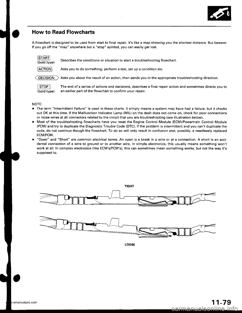
brARn
t.-OotO tw"t Describes the conditions or situation to start a troubleshooting flowchart.
FcTloNl Asks you to do something; perform a test, set up a condition etc.
@ Asks you about the result of an action, then sends you in the appropriate troubleshooting direction.
fS-OPl The end of a series of actions and decisions, describes a final repair action and sometimes directs you to
(bold type) an earlier part of the flowchart to confirm your repair.
NOTE:
. The term "lntermittent Failure" is used in these charts. lt simply means a system may have had a failure, but it checks
out OK at this time. lf the Malfunction Indicator Lamp (MlL) on the dash does not come on, check for poor connections
or loose wires at all connectors related to the circuit that you are troubleshooting (see illustration below).
. Most of the troubleshooting flowcharts have you reset the Engine Control Module (EcM)/Powertrain Control Module(PCM) and try to duplicate the Diagnostic Trouble Code (DTC). lf the problem is intermittent and you can't duplicate the
code, do not continue though the flowchart. To do so will only result in confusion and, possibly, a needlessly replaced
ECM/PCM,
o "Open" and "Short" are common electrical terms. An open is a break in a wire or at a connection. A short is an acci-
dental connection of a wire to ground or to another wire. ln simple electronics, this usually means something won't
work at all. In complex electronics (like ECM'S/PCM'S), this can sometimes mean something works, but not the way it's
suooosed to.
LOOSE
11-79
www.emanualpro.com
Page 283 of 1395

Fuel Cut-off Control
. During deceleration with the throttle valve closed, current to the fuel injectors iscutoffto improvefuel economyat
speeds over 970 rpm ('97 - 98 models), 920 rpm ('99 - 00 modelsl.
. Fuel cut-off action also takes place when engine speed exceeds 6,500 rpm ('97 - 98 models), 6900 rpm ('99 - 00
models), regardless of the position of the throttle valve, to protect the engine from over-rewing.
With Ay'T model. the PCM cuts the fuel at engine speeds over 5,000 rpm when the vehicle is not moving.*'�
4,./C Comoressor Clutch Relav
When the ECM/PCM receives a demand for cooling from the air conditioning system, it delays the compressor from
being energized, and enriches the mixture to assure a smooth transition to the Ay'C mode.
Evaporative Emission (EVAP) Purge Control Solenoid Valve
When the engine coolant temperature is above 154"F (68'C), the ECM/PCM controls the EVAP purge control solenoid
valve which controls vacuum to the EVAP purge control canister,
Alternator Control
The system controls the voltage generated at the alternator in accordance with the electrical load and driving mode.
which reduces the engine load to improve the fuel economy.
PCM Fail-saf e/Back-up Functions
1. Fail-safe Function
When an abnormality occurs in a signal from a sensor, the ECM/PCM ignores that signal and assumes a pre-pre
grammed value for that sensor that allows the engine to continue to run.
2. Back-up Function
When an abnormality occurs in the ECM/PCM itself, the fuel injectors are controlled by a back-up circuit independent
of the system in order to permit minimal driving.
3. Self-diagnosis Function IMalfunction Indicator Lamp (MlL)l
When an abnormality occurs in a signal from a sensor, the ECM/PCM supplies ground for the MIL and stores the DTC
in erasable memory. When the ignition is initially turned on {ll), the ECM/PCM supplies ground for the MIL for two
seconds to check the MIL bulb condition.
4. Two Trio Detection Method
To prevent false indications, the Two Trip Detection Method is used for the HO2S*1, fuel metering-related. idle control
system, ECT sensor and EVAP control system self-diagnostic functions. When an abnormality occurs, the ECM/PCM
stores it in its memory. When the same abnormality recurs after the ignition switch is turned OFF and ON (ll) again,
the ECM/PCM informs the driver by lighting the MlL. However, to ease troubleshooting, this function is cancelled
when you jump the service check connector, The MIL will then blink immediately when an abnormality occurs.
5. Two (or Three) Driving Cycle Detection Method {'97 model)
A "Driving Cycle" consists of starting the engine, beginning closed loop operation, and stopping the engine. lf misfir-
ing that increases emissions or EVAP control system malfunction is detected during two consecutive driving cycles.
or TWC deterioration is detected during three consecutive driving cycles, the ECM/PCM turns the MIL on. However, to
ease troubleshooting, this function is cancelled when you jump the service check connector. The MIL will then blink
immediately when an abnormality occurs.
*1: '97 - 98 models*2: '99 - 00 models
5.
www.emanualpro.com
Page 372 of 1395

ldle Control System
ldle Speed Setting (cont'd)
38 - 0O mod6l3:
NOTE: Before setting the idle speed, check the follow-
ing items:- The MIL has not been reported on.- lgnition timing- Spark plugs
- Air cleaner- PCV system
1. Start the engine. Hold the engine at 3.000 rpm with
no load (in Park or neutral) until the radiator fan
comes on, then let it idle.
Connect a tachometer.
Disconnect the IAC valve 2P connector and the EVAP
purge control solenoid valve 2P connector.
CONTROLSOLENOID VALVE
SOLENOID VALVE
lf the engine stalls, restart the engine with the accel-
erato. pedal slightly depressed. Stabilize the rpm at
1,000, then slowly release the pedal until the engine
idles.
Che€k the idle in no-load conditions: headlights, blow-
er fan, rear defogger, radiator fan, and air conditioner
are not operating,
ldle speed should bo:
480 t 50 rpm {in PErk or noutrall
11-170
lf necessary, adjust the idle speed, by turning the
idle adjusting screw.
After adjusting the idle speed, recheck the ignition
timing (see section 4). lf it is out of spec, go back to
steo 4.tDt.E
6. Turn the ignition switch OFF.
7. Reconnect the 2P connectors to the IAC valve and
the EVAP purge control solenoid valve, then do the
ECM/PCM reset procedure.
8. Restart and idle the engine with no-load conditions
for one minute, then check the idle speed.
ldle speod should be:,98 model:
750 t 50 rpm tin Park or neutral)'9!l - 00 modsls:
730 i 50 lpm lin Psrk or neutral)
NOTE: lf the idle speed increases to 780 t 50 rpm(770 1 50 rpml*, this means the EVAP system is
purging the canister. To stop the purging temporari-
ly, raise the engine speed above 1,000 rpm with the
accelerator pedal, then slowly release the pedal.*: '99 - 00 models
9. Let the engine idle for one minute with the head-
lights (Low) ON, and check the idle speed.
ldle speed should be:
38 mod6l:
750 f 50 rpm (in Palk or neutrall'99 - 00 modols:
730 t 50 rpm (in Palk or neutral)
10. Turn the headlights off. Let the engine idle for one
minute with the heater fan switch at Hl and air con-
ditioner on, then check the idle speed.
ldls spqed should be:'98 model:
780 t 50 rpm (in Park or neutrall'99 - 00 mod€ls:
7701 50 rpm lin Park or neutral)
lf the idle speed is not within specification. see the
Symptom Chart on page 11-64.
ADJUSTING
www.emanualpro.com
Page 520 of 1395
Description
General Operation (cont'dl
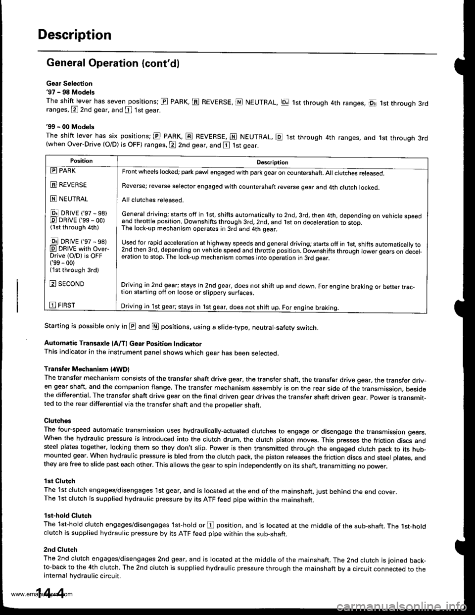
Gsar Selection'97 - 98 Models
The shift lever has seven positions; El PARK, ts REVERSE, N NEUTRAL, Ell 1st through 4th ranges, lpq 1st th.ough 3rdranges, P 2nd gear, and [ 1st gear
'99 - 00 Models
The shitt lever has six positions; El PARK, E REVERSE, E NEUTRAL. E ,lst through 4th ranges, and 1st through 3rd(when Over-Drive (O/D) is OFF) ranges. @ 2nd gear, and E 1st gear.
Starting is possible only in @ and @ positions. using a slide-type. neutral-safety switch.
Automatic Transaxle (A/T) Gear Position IndicatorThis indicator in the instrument panel shows which gear has been selected.
Transler Mochanism {4WD}
The transfer mechanism consists of the transfer shaft drive gear. the transfer shaft. the transfer drive gear, the transfer driv-en gear shaft, and the companion flange, The transfer mechanism assembly is on the rear side ot the transmission. besidethe differential. The transfer shaft drive gear on the final driven gear drives the transfer shaft driven qear. power is transmit-ted to the rear differential via the transfer shaft and the Drooeller shaft.
Clutches
The four-speed automatic transmission uses hydraulically-actuated clutches to engage or disengage the transmission gears.When the hydraulic pressure is introduced into the clutch drum, the clutch piston moves. This presses the friction discs andsteel plates together, locking them so they don't slip. Power is then transmifted through the engaged clutch pack to its hu$mounted gear. When hydraulic pressure is bled from the clutch pack, the piston releases the friction discs and steel plates, andthey are free to slide past each other. This allows the gearto spin independently on its shaft, transmitting no power.
lst Clutch
The 1st clutch engages/disengages lst gear, and is located at the end ofthe mainshaft, just behind the end cover.The 1st clutch is supplied hydraulic pressure by its ATF feed pipe within the mainshaft.
lst-hold Clutch
The 1st-hold clutch engages/disengages 1st-hold or E position, and is located at the middle of the sub-shaft. The 1st-holdclutch is supplied hydraulic pressure by its ATF feed pipe within the sub-shaft.
2nd Clutch
The znd ciutch engages/disengages 2nd gear, and is located at the middle of the mainshaft. The 2nd clutch is joined back-to-back to the 4th clutch. The 2nd clutch is supplied hydraulic pressure through the mainshaft by a circuit connected to theinternal hydraulic circuit.
PositionDescription
Reverse; reverse selector engaged with countershaft reverse gear and 4th clutch locked.
Allclutches released.
General driving; starts off in 1st, shifts automatically to 2nd, 3rd, then 4th, depending on vehicle speedand throftle position. Downshifts through 3rd,2nd, and lst on deceleration to stop.The lock-up mechanism operates;n 3rd and 4th gear.
used for rapid €cceleration at highway speeds and general driving; stans off in 1st, shifts automatically to2nd_then 3rd, dejending on vehicle speed and throttle position. Downshifts through lower gears on decel-eration to stop. The lock-up mechanism comes into operation in 3rd gear.
Driving in 2nd_gear; stays in 2nd gear, does not shift up and down. For engine braking or better trac_tion starting off on loose or slippery surfaces.
Driving in 1st gear; stays in 1st gear, does not shift up. For engine braking.
tll PARK
t!!l l|EvEn>E
E NEUTRAL
Ell DRrvE ('97 - sB)E DRrvE ('ss - oo)(1st through 4th )
E DRrvE {'97 - s8)O DRTVE with over-Drive (O/D) is OFF('99 - 00)(1st through 3rd)
E SECOND
E FIRST
14-4
www.emanualpro.com
Page 859 of 1395
Inspection and Adjustment
Pump Belt
When using a new belt. first adjust the deflection or ten-
sion to the values for the new belt, then readjust the
deflection or tension to the values for the used belt after
running engine for five minutes.
Inspection
Note these items during inspection:
a lf there are cracks or any damage evident on the belt,
replace it with a new one.
. Follow the manufacturer's instructions lor the tension
gauge.
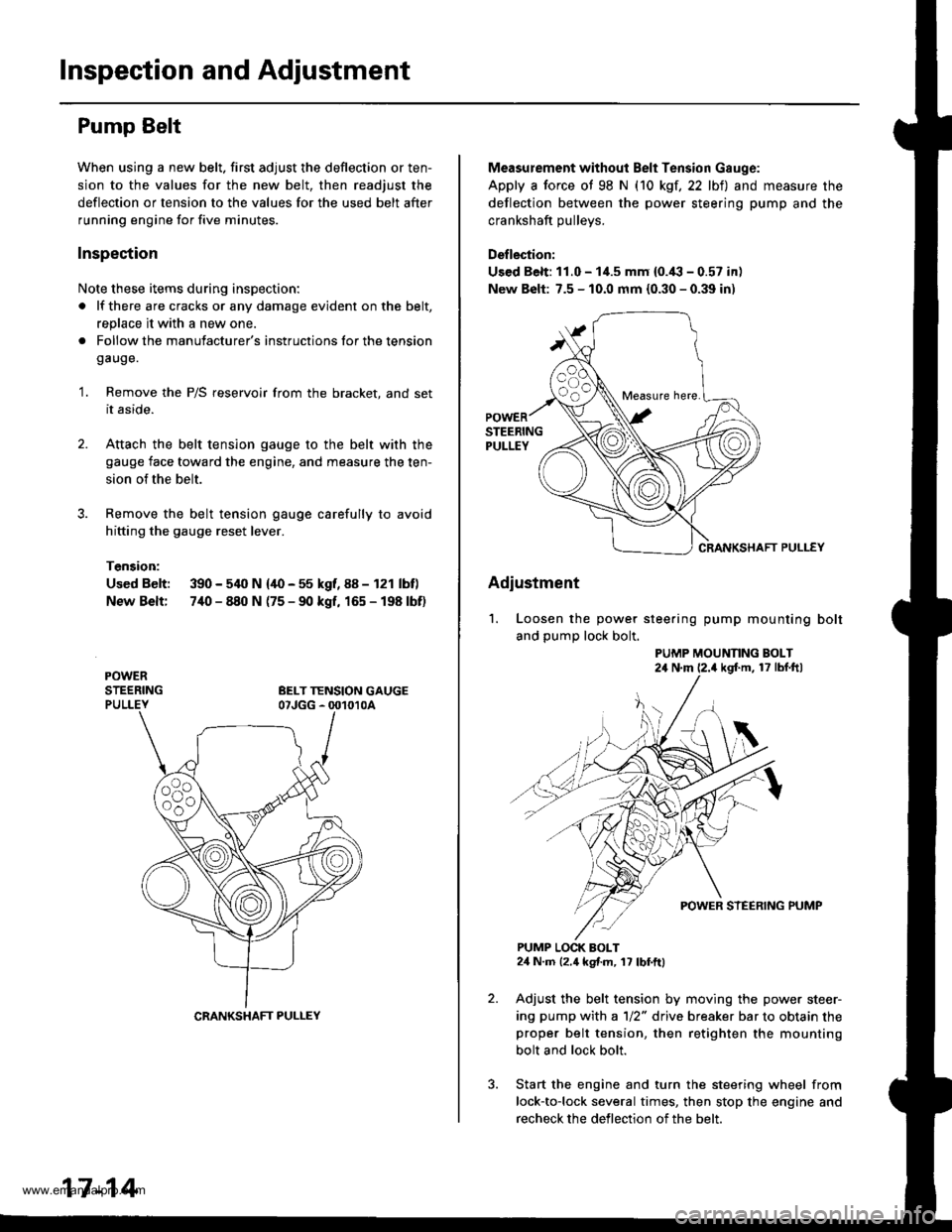
'1. Remove the P/S reservoir from the bracket, and set
it aside.
2. Attach the belt tension gauge to the belt with the
gauge face toward the engine, and measure the ten-
sion of the belt.
Remove the belt tension gauge carefully to avoid
hitting the gauge reset lever.
Tension:
Used Belt: 390 - 540 N {40 - 55 kgf, 88 - 121 lbf)
New Belt: 7,[0 - 840 N (75 - 90 kgf, 165 - 198 lbf)
CRANKSHAFT PULLEY
17-14
Measurement without Belt Tension Gauge:
Apply a force ot 98 N (10 kgf,22 lbt) and measure the
deflection between the power steering pump and the
crankshaft oullevs.
Deflection:
Used Belt: 11.0 - 1i1.5 mm {0.'(l - 0.57 in)
New Belt: 7.5 - 10.0 mm {0.30 - 0.39 in)
CRANKSHAFT PULLEY
Adiustment
'1. Loosen the power steering pump mounting bolt
and pump lock bolt.
PUMP MOUNNNG BOLT24 N'm (2.4 kgf'm, 17 lbf ftl
PUMP LOCK BOLT24 N.m 12.4 kgf.m, 17 lbf.ftl
Adjust the belt tension by moving the power steer-
ing pump with a 1/2" drive breaker bar to obtain theproper belt tension, then retighten the mounting
bolt and lock bolt.
Start the engine and turn the steering wheel from
lock-to-lock several times, then stop the engine and
recheck the deflection of the belt.
Measure here.
www.emanualpro.com
Page 860 of 1395
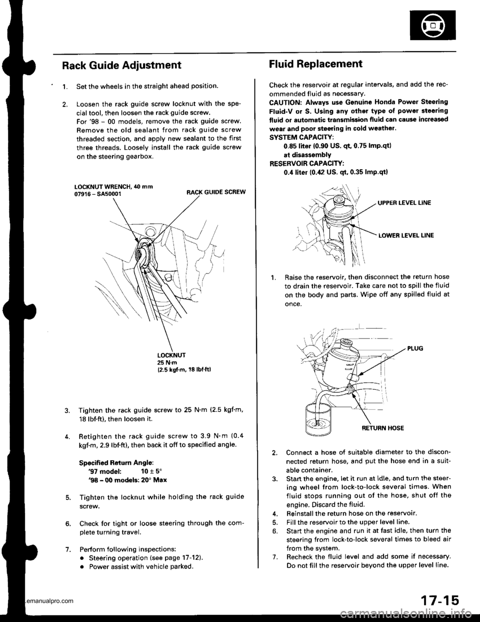
Rack Guide Adjustment
1.
6.
7.
5.
4.
Set the wheels in the straight ahead position.
Loosen the rack guide screw locknut with the spe-
cialtool, then loosen the rack guide screw.
For'98 - 00 models, remove the rack guide screw.
Remove the old sealant from rack guide screw
threaded section, and apply new sealant to the first
three threads. Loosely install the rack guide screw
on the steering gearbox.
RACK GUIDE SCREW
LOCKNUT25 N.m
12.5 kgt m, 18lbtftl
Tighten the rack guide screw to 25 N.m (2.5 kgf'm,
18 lbf.ft), then loosen it.
Retighten the rack guide screw to 3.9 N'm (0.4
kgf.m, 2.9 lbf.ft), then back it off to specified angle.
Specified Return Anglo:
37 model: 10 r 5"'98 - 00 modeb: 20' Max
Tighten the locknut while holding the rack guide
screw.
Check for tight or loose steering through the com-
plete turning travel.
Perform following inspections:
. Steering operation (see page 17-12).
. Power assist with vehicle parked
Fluid Replacement
Check the reseryoir at regular intervals, and add the rec-
ommended fluid as necessary.
CAUTION: Always use Gsnuine Honda Power Steering
Fluid-V or S. Using any other type of power steering
tluid or automatic transmission fluid can cause increassd
wear and poor steering in cold w3athel.
SYSTEM CAPACITY:
0.85 liter {0.90 US. qt. 0.75 lmp.qtl
at disasssmbly
RESERVOIR CAPACITY:
0.,1 liter (0.42 US. gt, 0.35 lmp.qi)
UPPEN LEVEL LINE
LOWER LEVEL LINE
1.Raise the reservoir. then disconnect the return hose
to drain the reservoir. Take care not to spill the fluid
on the body and parts. Wipe off any spilled fluid at
once.
2, Connect a hose of suitable diameter to the discon-
nected return hose, and put the hose end in a suit-
able container.
3. Stan the engine. let it run at idle, and turn the steer-
ing wheel from lock-to-lock several times. When
fluid stops running out of the hose, shut off the
engine. Discard the fluid.
4. Beinstallthe return hose on the reservoar.
5. Fill the reservoir to the upper level line,
6. Start the engine and run it at fast idle. then turn the
steering from lock-to-lock several times to bleed air
from the system.
7. Recheck the fluid level and add some if necessary.
Do not fill the reservoir beyond the upper level line.
www.emanualpro.com
Page 939 of 1395
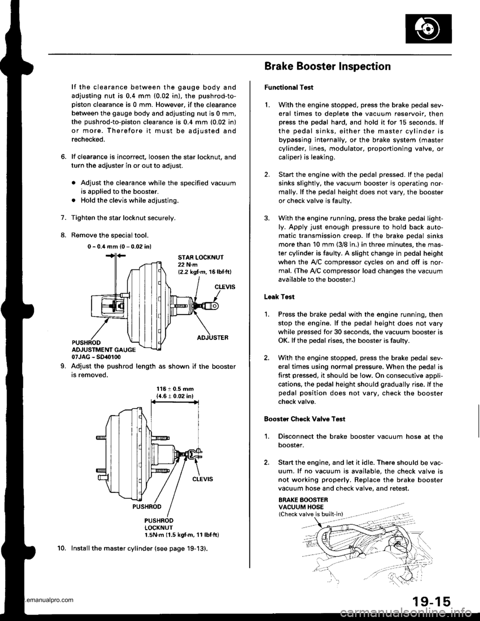
6.
7.
8.
lf the clearance between the gauge body and
adjusting nut is 0.4 mm (0.02 in), the pushrod-to-
piston clearance is 0 mm. However. if the clearance
between the gauge body and adjusting nut is 0 mm,
the pushrod-to-piston clearance is 0.4 mm (0.02 in)
or more. Therefore it must be adjusted and
recheck€d.
lf clearance is incorrect, loosen the star locknut, and
turn the adjuster in or out to adjust.
. Adjust the clearance while the specified vacuum
is applied to the booster.
. Hold the clevis while adjusting.
Tighten the star locknut securely.
Remove the special tool.
0 - 0.4 mm (0 - 0.02 inl
Adjust the pushrod length as shown if the
is removed,
booster
11610.5 mm{4.6 t 0.02 inl
PUSHRODLOCKNUT1.5N.m 11.5 kgf.m. '11 lbtfl)
Install the master cylinder (see page 19-13).
9.
STAR LOCKNUT22 N.m12.2 kgt m. 16 lbtftl
10.
(Check valve is built-in)
Brake Booster Inspection
FunctionalTest
1. With the engine stopped, press the brake pedal sev-
eral times to deplete the vacuum reservoir. thenpress the pedal hard, and hold it for 15 seconds. lf
the pedal sinks, either the master cylinder is
bypassing internally, or the brake system (master
cylinder, lines, modulator, proportioning valve. or
caliper) is leaking.
2. Start the engine with the pedal pressed. lf the pedal
sinks slightly. the vacuum booster is operating nor-
mally. lf the pedal height does not vary, the booster
or check valve is faultv.
3. With the engine running, press the brake pedal light-
ly. Apply just enough pressure to hold back auto-
matic transmission creep. lf the brake pedal sinks
more than 10 mm (3/8 in.) in three minutes, the mas-
ter cylinder is faulty. A slight change in pedal height
when the Ay'C compressor cycles on and off is nor-
mal. (The Ay'C compressor load changes the vacuum
available to the booster.)
Leak Test
1.Press the brake pedal with the engine running, then
stop the engine. lf the pedal height does not vary
while pressed for 30 seconds, the vacuum booster is
OK. lf the pedal rises, the booster is faulty.
With the engine stopped, press the brake pedal sev-
eral times using normal pressure. When the pedal is
first pressed. it should be low, On consecutive appli-
cations, the pedal height should gradually rise. lf thepedal position does not vary. check the booster
check valve.
Boostor Chock Valve Test
1. Disconnect the brake booster vacuum hose at the
booster.
2. Start the engine, and let it idle. There should be vac-
uum. lf no vacuum is available, the check valve is
not working properly. Replace the brake booster
vacuum hose and check valve. and retest.
ERAKE BOOSTERVACUUM HOSE
www.emanualpro.com
Page 953 of 1395
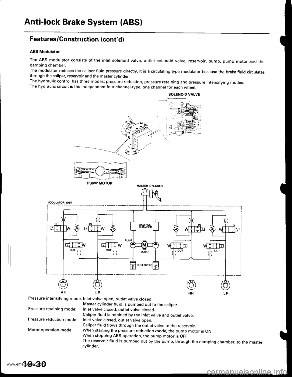
Anti-lock Brake System (ABS)
Features/Gonstruction (cont'd)
ABS Modulator
The ABS modulator consists of the inlet solenoid valve, outlet solenoid valve, reservoir, pump, pump motor and thedampjng chamber.
The modulator reduces the caliper fluid pressure directly. lt is a circulating-type modulator because the brake fluid circulatesthrough the caliper, reservoir and the master cylinder.The hydraulic control has three modes: pressure reduction, pressure retaining and pressure intensifying modes.The hydraulic circuit is the independent four channel-type, one channel for each wheel.
SOLENOID VALVE
t-
Pressure intensifying mode: Inlet valve open, outlet valve closed,
Pressure retaining mode:
Pressure reduction mode:
Motor operation mode:
Master cylinder fluid is pumped out to the caliper.Inlet valve closed, outlet valve closed.
Caliper fluid is retained by the inlet valve and outlet valve.Inlet valve closed, outlet valve ooen
Caliper fluid flows through the outlet valve to the reservoir.When starting the pressure reduction mode. the pump motor is ON.When stopping ABS operation, the pump motor is OFF.The reservoir fluid is pumped out by the pump, through the damping chamber, to the mastercylinder.
PUMP MOTOR
19-30
www.emanualpro.com