Heater cable HONDA CR-V 1997 RD1-RD3 / 1.G Workshop Manual
[x] Cancel search | Manufacturer: HONDA, Model Year: 1997, Model line: CR-V, Model: HONDA CR-V 1997 RD1-RD3 / 1.GPages: 1395, PDF Size: 35.62 MB
Page 105 of 1395
rd
te
n-
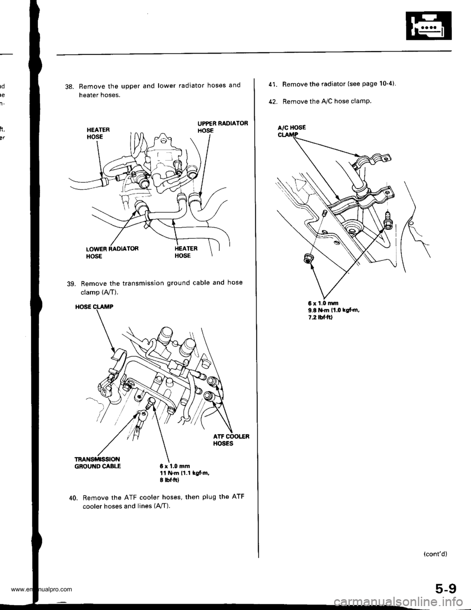
38. Remove the upper and lower radiator hoses and
heater hoses.
39. Remove the transmission ground cable and hose
clamp (A,/T).
GBOUI{DCABLE 6x 1,0 mm11 N.m 11.1 lof'm,I tbf.ftl
40. Remove the ATF cooler hoses, then plug the ATF
cooler hoses and, n"" lAfI).
rt,
BT
6xl,0mm
A/C HOSE
41.
42.
Remove the radiator (see page 10"4).
Remove the IVC hose clamp.
9.8 'm lt.o klt m,l.2tutal
(cont'd)
5-9
www.emanualpro.com
Page 112 of 1395
Engine Removal/lnstallo cton
Installation (cont'd)
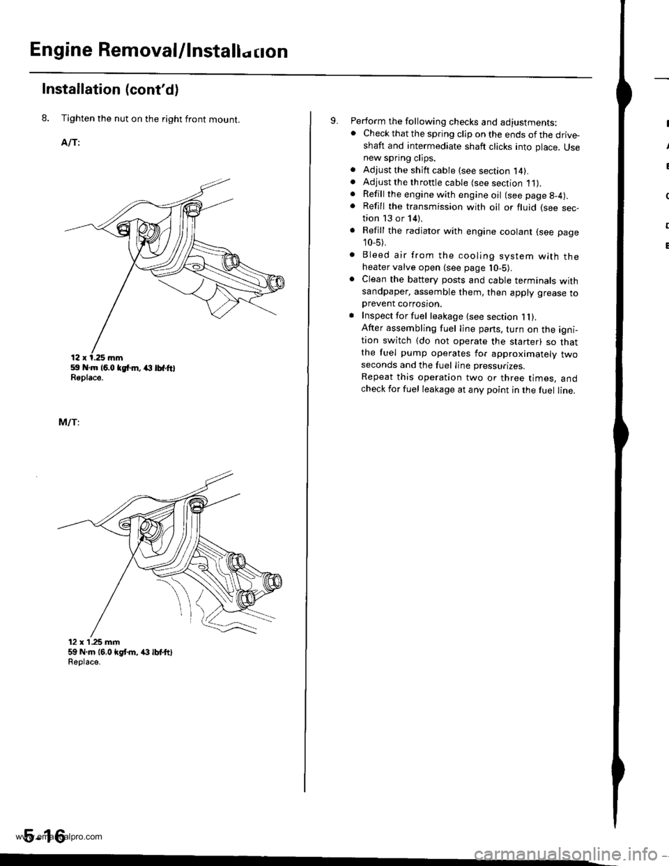
8. Tighten the nut on the right front mount.
AlTi
59 .m 16.0 tgt m, (l lbfftlReplace.
MlTi
12 x'1.25 mm59 N.m 16,0 kgt m, /(} lbt ttlReolace.
5-16
9. Perform the following checks and adjustments:. Check that the spring clip on the ends of the drive-shaft and intermediate shaft clicks into place. Usenew spring clips.. Adjust the shift cable (see section l4).. Adjust the throttle cable (see section 11).. Refill the engine with engine oil (see page g-4).
. Refill the transmission with oil or fluid (see sec-tion 13 or 14).
. Refill the radiator with engine coolant (see page
10_5).
. Bleed air from the cooling system with theheater valve open (see page l0-5).. Clean the battery posts and cable terminals withsandpaper, assemble them, then apply grease toDrevent corrosron.. Inspect for fuel leakage (see section 1l).After assembling fuel line pans, turn on the igni-tion switch (do not operate the starter) so thatthe fuel pump operates for approximately twoseconds and the fuel Iine pressurizes.
Repeat this operation two or three times, andcheck for fuel leakage at any point in the fuel line.
www.emanualpro.com
Page 204 of 1395

Fuel and Emissions
Special Tools ...................... 11-2
Component Locations
lndex ...................... ....,.... 11-3
Svstem Description
Vacuum Connections ...........,....,.,................. 1 1-9
Electrical Connections ................................... 1 1-15
System Connectors .,.,,.,............................,.,. 1 1-36
Troubleshooting
Troubleshooting Procedures,.,..................... 11-60
Engine Control Module/Powertrain ConttolModule Terminal Arrangement .............., 11-67
Diagnostic Trouble Code Chart .................... 1 t-75
How to Read Flowcharts .......,.....,.,............... I 1-79
PGM-Fl System
System Description .................,.,.,,,............... 1 1-80
Troubleshooting Flowcharts
Engine Control Module/PowertrainControl Module ........11-52
Manifold Absolute Pressure Sensor ............. 11-90
Intake Air Temperature Sensor .................... 1 1-95
Engine Coolant Temperature Sensor .,..,.,.... 1 1-99
Throttle Position Sensor ...........,.....,.,.,..,...... I 1'103
Primary Heated Orygen Sensor (Sensor 1) ... 11-110
Secondary Heated Oxygen Sensor{Sensor 2l .................. 1 1-117
Heated Oxygen Sensor Heater ..................... 11-121
Fuef Supply System ......11-124
Random Misfire ,....,.,..... 11-126
Mistire Detected in One Cylinder .....-........... 11-128
Knock Sensor ................ 11-130
CKP/TDC/CYP Sensor .................................... 1 1-131
Vehicle Speed Sensor ...............................,.... 1 1-135
Barometric Pressure Sensor .....,...,...,.,,........ 1 1-137
Electrical Load Detector ...,.,.......................... 1 1-138
CKF Sensor ................,.,, '11-112
ECM/PCM lnternaf Circuit ............................. 11'117
HO2S Replacement .,.,.,. 11-148
ldle Control System
System Description ............ 11-149
Troubleshooting Flowcharts
ldle Control System ...... 11-150
fdle Air Control Valve ......................,............. 11-152
Air Conditioning Signal ................................. I 1-155
Alternator FR Signal ...................................... 1 1-159
Starter Switch Si9na1 .................................... t l-161
Power Steering Pressure Switch Signal ...... 11-162
Brake Switch Si9na1 ...................................... 11-166
Fast ldle Thermo Valve .,.,.............................,.,.,. 11-168
ldle speed setting .............. 11-169
Fuel Supply System
Fuel Lines ............................ 11-171
Fuef Tube/Ouick-Conneci Fittings ..................... 11 -175
System Description ............ 11-178
Fuel Pressurg ...................... 11-178
Fuel Iniectors ................,..... 11-179
Fuel Pressure Re9u1ator .............................,.,...., f 1-181
Fuef Fifter ....,.,.,.,,,,.,............11-142
Fuel Pump ........................... 11-183
Fuel Gauge .......................... 11-184
Fuel Gauge Sending Unit ................................... I 1-185
Low Fuel Indicator System ...........,.,..,............... 1 1-185
PGM-FI Main Relay ............. 11-187
Fue|Tank................ ............. 11-191
Intake Air System
System Description ............ 11-193
Air Cleanel ,.,.,..................... 11-194
Throttle Cable ..................... 11-194
Throttle Body........ .............. 11-196
Emission Control System
System D$cription ...,....,.,. 11-199
Tailpipe Emission ............... 11-199
Three Way Catalytic Converter ..................,.,...,, 11-199
Positive Crankcase Ventilation System .,.,,,,.,.., 11-2O1
Evaporative Emission Controls .........,.,.,............ 11-203
www.emanualpro.com
Page 1094 of 1395
Component Location
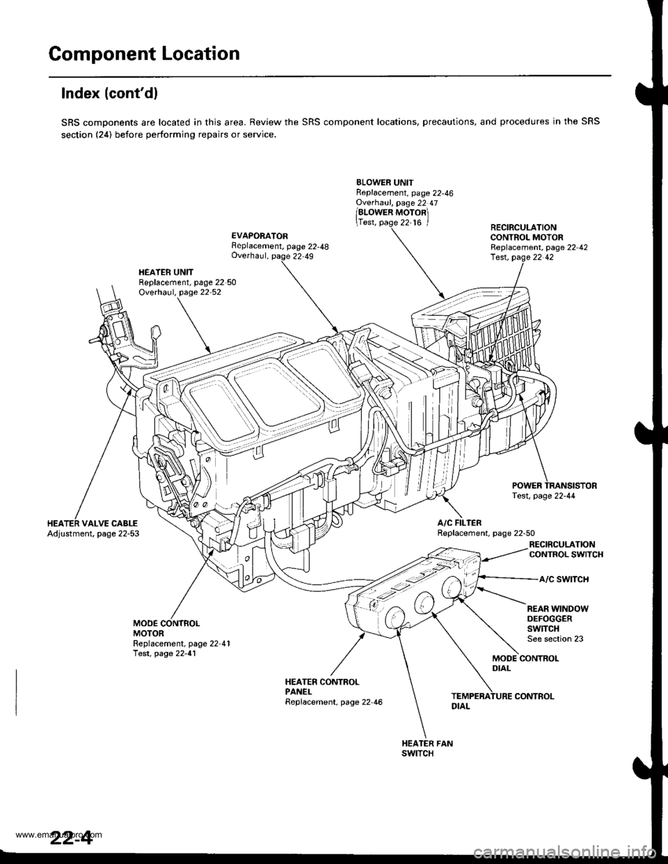
lndex (cont'dl
SRS components are located in this area. Review the SRS component locations, precautions, and procedures in the SRS
section (24) before performing repairs or service.
BLOWER UNITReplacement, page 22-46Ovethaul, page 22 47
/alowen ruoronl
\Test, page 22-16 /
EVAPORATORFeplacement, page 22-48Overhaul, page 22,49
RECIRCULATIONCONTROL MOTORReplacement, page 22 42
HEATER UNITReplacement, page 22 50Overhaul, page 22 52
lest, pag.e 22 42
A/C FILIERReplacement. page 22-50VALVE CABLEAdjustment, page 22-53
RECIRCULATIONCONTROL SWITCH
a/c swtTcH
MODEMOTOR
REAR WINDOWDEFOGGERSwlTCHSee section 23Replacement, page 22-41Test, page 22-41MODE CONTROLDIAL
HEATER CONTROLPANELReplacement, page 22 46
swtTcH
22-4
CONTROL
www.emanualpro.com
Page 1140 of 1395
A/C FilterHeater Unit
Replacement
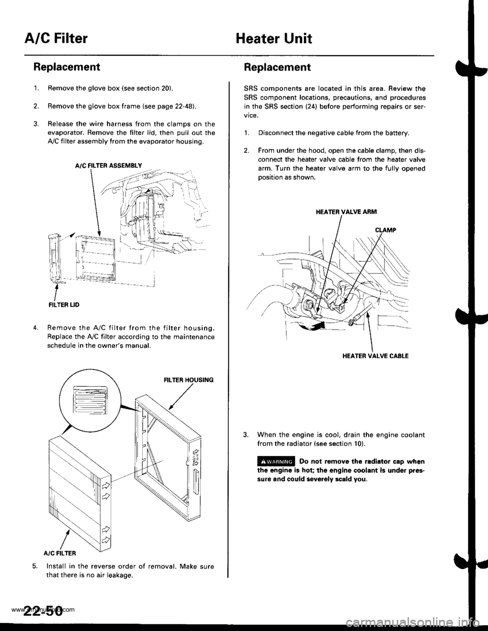
1.Remove the glove box (see section 20).
Remove the glove box frame {see page 22-4A).
Release the wire harness from the clamps on the
evaporator. Remove the filter lid, then pull out the
,VC filter assembly from the evaporator housing.
A/C FILTER ASSEMELY
Remove the A/C filter from the filter housing.
Replace the Ay'C filter according to the maintenance
schedule in the owner's manual.
Install in the reverse order of removal. Make sure
that there is no air leakage.
22-50
Replacement
SRS components are located in this area. Review the
SRS component locations, precautions, and procedures
in the SRS section {24) before performing repairs or ser-
1. Disconnect the negative cable from the battery.
2. From under the hood, open the cable clamp, then dis-
connect the heater valve cable from the heater valve
arm. Turn the heater valve arm to the fullv ooened
oosition as shown.
When the engine is cool, drain the engine coolant
from the radiator (see section 10).
@ Do not remove the rldiator cap when
the engine is hot; the engine coolant is under pres-
sure and could sevo.ely scald you.
HEATER VALVE ARM
HEATER VALVE CABLE
www.emanualpro.com
Page 1141 of 1395
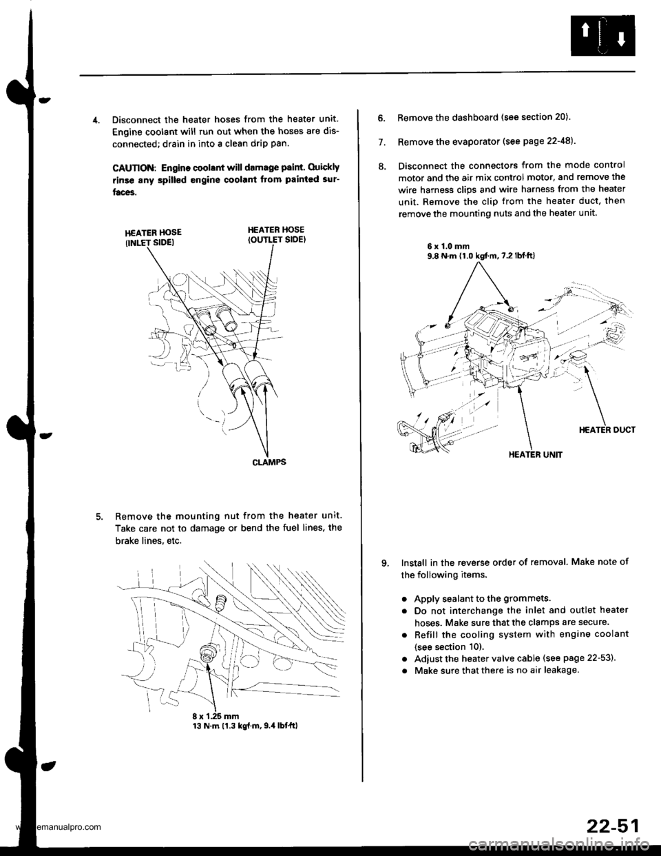
4. Disconnect the heater hoses from the heater unit.
Engine coolant will run out when the hoses are dis-
connected; drain in into a clean drip pan.
CAUTION: Engino coolant will damage p8int. Ouickly
rinse any spill€d engine coolant Itom painted sur-
faces.
HEATER HOSEIOUTLET SIDE)
Remove the mounting nut from the heater unit.
Take care not to damage or bend the fuel lines, the
brake lines. etc.
CLAMPS
13 N.m 11.3 kg{.m,9.4 lbtftl
22-51
7.
ll.
Remove the dashboard (see section 20).
Remove the evaporator (see page 22-48).
Disconnect the connectors from the mode control
motor and the air mix control motor, and remove the
wire harness clips and wire harness from the heater
unit. Remove the clip from the heater duct, then
remove the mounting nuts and the heater unit
6x1.0mm9,8 N.m (1.0 kgt m,7.2lblft)
qInstall in the reverse order of removal. Make note of
the following items.
a
a
a
a
Apply sealant to the grommets.
Do not interchange the inlet and outlet heater
hoses. Make sure that the clamps are secure.
Refill the cooling system with engine coolant
{see section 10).
Adiust the heater valve cable (see page 22-53).
Make sure that there is no air leakage.
HEATER UNIT
www.emanualpro.com
Page 1143 of 1395
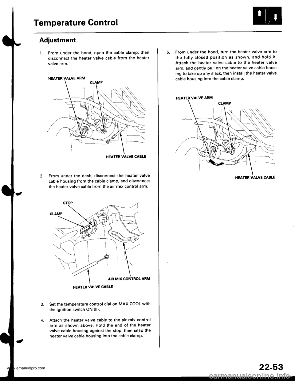
Temperature Control
Adjustment
l. From under the hood, open the cable clamp, then
disconnect the heater valve cable from the heater
vatve arm.
From under the dash, disconnect the heater valve
cable housing from the cable clamp. and disconnect
the heater valve cable from the air mix contlol arm
Set the temperature control dial on MAX COOL with
the ignition switch ON (ll).
Attach the heater valve cable to the air mix control
arm as shown above. Hold the end of the heater
valve cable housing against the stop, then snap the
heater valve cable housing into the cable clamp.
HEATER VALVE ARM
HEATER VALVE CABLE
5. From under the hood. turn the heater valve arm to
the fullv closed position as shown, and hold it.
Attach the heater valve cable to the heater valve
arm, and gently pull on the heater valve cable hous-
ing to take up any slack, then install the heate. valve
cable housing into the cable clamp.
HEATER VALVE ARM
HEATER VALVE CABLE
22-53
www.emanualpro.com
Page 1171 of 1395

Gonnector ldentification and Wire Harness Routing
How to ldentity Connectors:
ldentification numbers have been assigned to all connectors, The number is preceded by the letter "C" for connectors.
"G" for ground terminals or "T" for non-ground terminals.
Location
HarnessEngine CompartmsntDashboardOthers lFloor, Door,
8oof, Tailgate)
Starter cableT1, T2 and @
Battery ground cableG1 and O
Engine ground cableT3
Transmission ground cableT4
G3
Engine wire harnessC101 through C137
T101 and T102
G101
Engine compartment ware harnessC201 through C218
G201 and G202
Under-hood ABS fuse/relay box
wire harness
t5ano9
Main wire harnessC301 through C309
C351 through C361
C401 through C447
G401 and G402
Dashboard wire harnessC501 through C524 (C525)
G501
Left side wire harnessC551 through C581
G551, G552 and G553
Right side wire harnessC601 through C605
lnterior wire harnessC701 through C703
Rear bumper wire harnessC641 through C643
Heater sub-harnessC731 through C740
Secondary heated oxygen sensor
sub-harness
C721 through C722
Combination switch sub-harnessC751 through C760
Driver's door wire harnessC661 through C667
Front passenger's door wire harnessC6Tl through C676
Left rear door wire harnessC681 through C684
Right rear door wire harnessC69'l through C694
Rear wire harnessC611 through C520
Tailgate wire harnessC631 through C634
G631
SRS main harnessC801 through C808
G801
High mount brake light sub-harnessC651 through C653
Fuel tank oressure sensor sub-harnessC645 through C647
www.emanualpro.com