boot HONDA CR-V 1997 RD1-RD3 / 1.G User Guide
[x] Cancel search | Manufacturer: HONDA, Model Year: 1997, Model line: CR-V, Model: HONDA CR-V 1997 RD1-RD3 / 1.GPages: 1395, PDF Size: 35.62 MB
Page 821 of 1395
Front Driveshafts
Disassembly (cont'd)
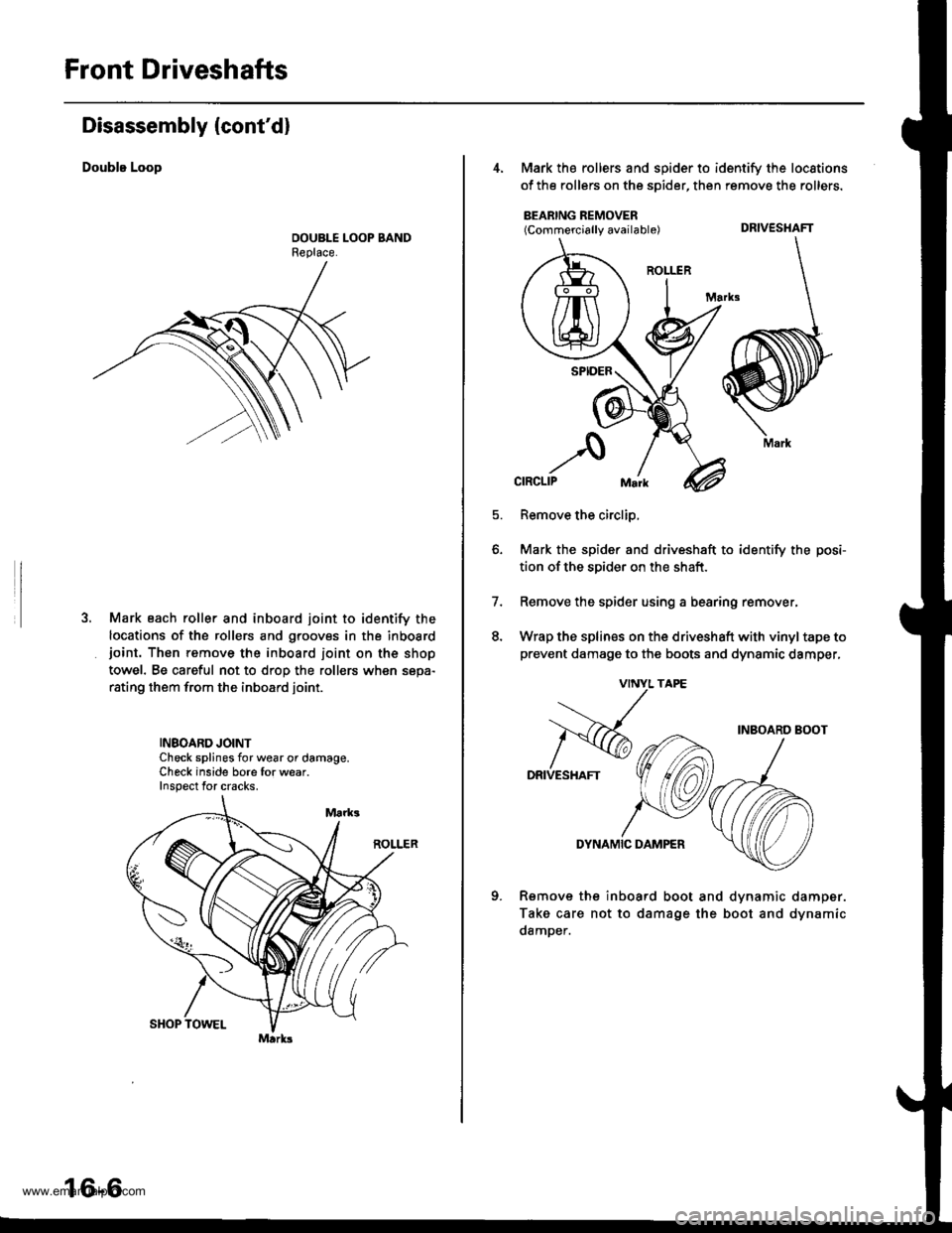
Double Loop
Mark each roller and inboard joint to identify the
locations of the rollers and grooves in the inboardjoint. Thon remove the inboard ioint on the shop
towel. Be careful not to drop the rollers when sepa-
rating them from the inboard joint.
INBOARD JOINTCheck splines for wear or damage.Check inside bore for wear.Inspect for cracks.
16-6
4, Mark the rollers and spider to identify the locstions
of the rollers on the sDider, then remove the rollers.
BEARING REMOVER(Commercially available) DRIVESHAFT
Remove the circlip,
Mark the spider and driveshaft to identify the posi-
tion ofthe spider on the shaft.
Remove the spider using a bearing remover,
Wrap the splines on the driveshaft with vinyl tape to
prevent damage to the boots and dynsmic damper,
7.
q
INBOARD BOOT
DRIVESHAFT
DYNAMIC DAMPER
Rsmove the inboard boot and dvnamic
Take care not to damage the boot and
damDer.
damper.
dynamic
DRIVESHAFT
Mark
www.emanualpro.com
Page 822 of 1395
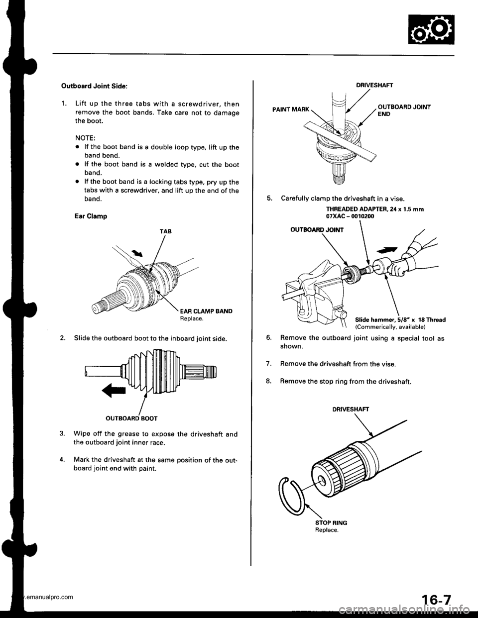
Outboard Joint Side:
1. Lift up the three tabs with a screwdriver, then
remove the boot bands, Take care not to damage
the boot.
NOTE:
. lf the boot band is a double loop type, lift up the
band bend.
. lf the boot band is a welded type, cut the boot
band.
. lf the bootband isa lockingtabstype. pry upthe
tabs with a screwdriver, and lift up the end of the
oano.
Ear Clamp
EAR CLAMP BANDReplace.
2. Slide the outboard boot to the inboard ioint side.
Wipe off the grease to expose the driveshaft andthe outboard joint inner race.
Mark the driveshaft at the same position of the out-
board joint end with paint.
TAB
DRIVESHAFT
PAINT MARK
5, Carefullv clamD the driveshaft in a vise.
THREADED AOAPTER,2iI x 1.5 mm07xAc - 0010200
Remove the outboard joint using a special tool asshown.
Remove the driveshatt trom the vise
Remove the stop ring from the driveshaft.
o.
7.
8.
STOP RINGReplace.
Slide hammc..5/8'x lS Throad(Commerically, available)
DRIVESHAFT
www.emanualpro.com
Page 823 of 1395
![HONDA CR-V 1997 RD1-RD3 / 1.G User Guide
Front Driveshafts
parts with solvent.
o *4@] :Thoroughly pack the inboard and outboard joints and both joint boots with the joint grease included in the
new driveshaft set.. The98 Canada model andal HONDA CR-V 1997 RD1-RD3 / 1.G User Guide
Front Driveshafts
parts with solvent.
o *4@] :Thoroughly pack the inboard and outboard joints and both joint boots with the joint grease included in the
new driveshaft set.. The98 Canada model andal](/img/13/5778/w960_5778-822.png)
Front Driveshafts
parts with solvent.
o *4@] :Thoroughly pack the inboard and outboard joints and both joint boots with the joint grease included in the
new driveshaft set.. The'98 Canada model andall '99 - 00 models use a TPE (Thermoplastic Polyester E lastomer) outboard joint boot.
Use the ear clamp type boot band in the outboard boot set.
Grease quantity:
Inboard Joint: All models 120 - 130 g (i1.2 - 4.6 oz)
Left inboard joint splines (Al: 0.5 - 1.0 g (0.018 - 0.035 oz)
Outboard Joint: '97 model and'98 USA model 130 - 140 g (4.6 -,1.9 oz)'98 Canada model and all '99 - 0O models 140 - 150 g 14.9 - 5.3 oz)
Reassembly
Note these items during reassembly
. Clean the disassembled parts with solvent, anddry them thoroughly with compressed air. Do not wash the rubber
INBOARO JOINT
SPIOERINBOARD BOOT
SET RINGReplace.
LEFT INBOAROJOINT
SPLINES: (Al-6rPack cavity with grease.
wtn grease.
BANDS
DYNAMIC DAMPER
STOP RINGReplace.
OUTBOARD BOOT
EAR CLAMPReplace.
ITPE)*I
-611
-/ Pack cavity with grease.
DOUELEReplace.BAND+'BAND*1
__G1Pack cavitywrtn grease.
OUTBOARD BOOT*'(RUBBERI
-GrjPack cavity*l: '98 Canada models, all '99-00models
*2: '97 - 98 models (except'98 Canada model)
16-8
wtrn grease.
www.emanualpro.com
Page 824 of 1395
Inboard Joint Side:
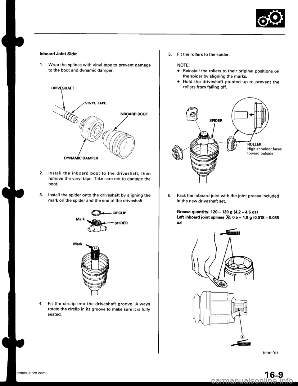
1. Wrap the splines with vinyl tape to prevent damage
to the boot and dynamic damper.
DRIVESHAFT
,..',NYL rAPE
V6
uu.oa.Dsoo.�
,",^_Y,C@
Install the inboard boot to the driveshaft, then
remove the vinyl tape. Take care not to damage the
boot.
Install the spider onto the driveshaft by aligning the
mark on the spider and the end of the driveshaft.
@+-crncr-rr
4.Fit the circlip into
rotate the circlip in
seated.
the driveshaft groove. Always
its groove to make sure it is fully
5. Fit the rollers to the spider.
NOTE:
. Reinstall the rollers to their original positions onthe spider by aligning the marks.
. Hold the driveshaft pointed up to prevent therollers from falling off.
Pack the inboard joint with the joint grease included
in the new driveshaft set,
Grease quantity: 120 - 130 g {4.2 - 4.6 oz)
Left inboad ioint splines @:0.5 - 1.0 g (0.018 - 0.m5
ozl
(cont'd)
F
16-9
www.emanualpro.com
Page 825 of 1395
Front Driveshafts
Reassembly {cont'd)
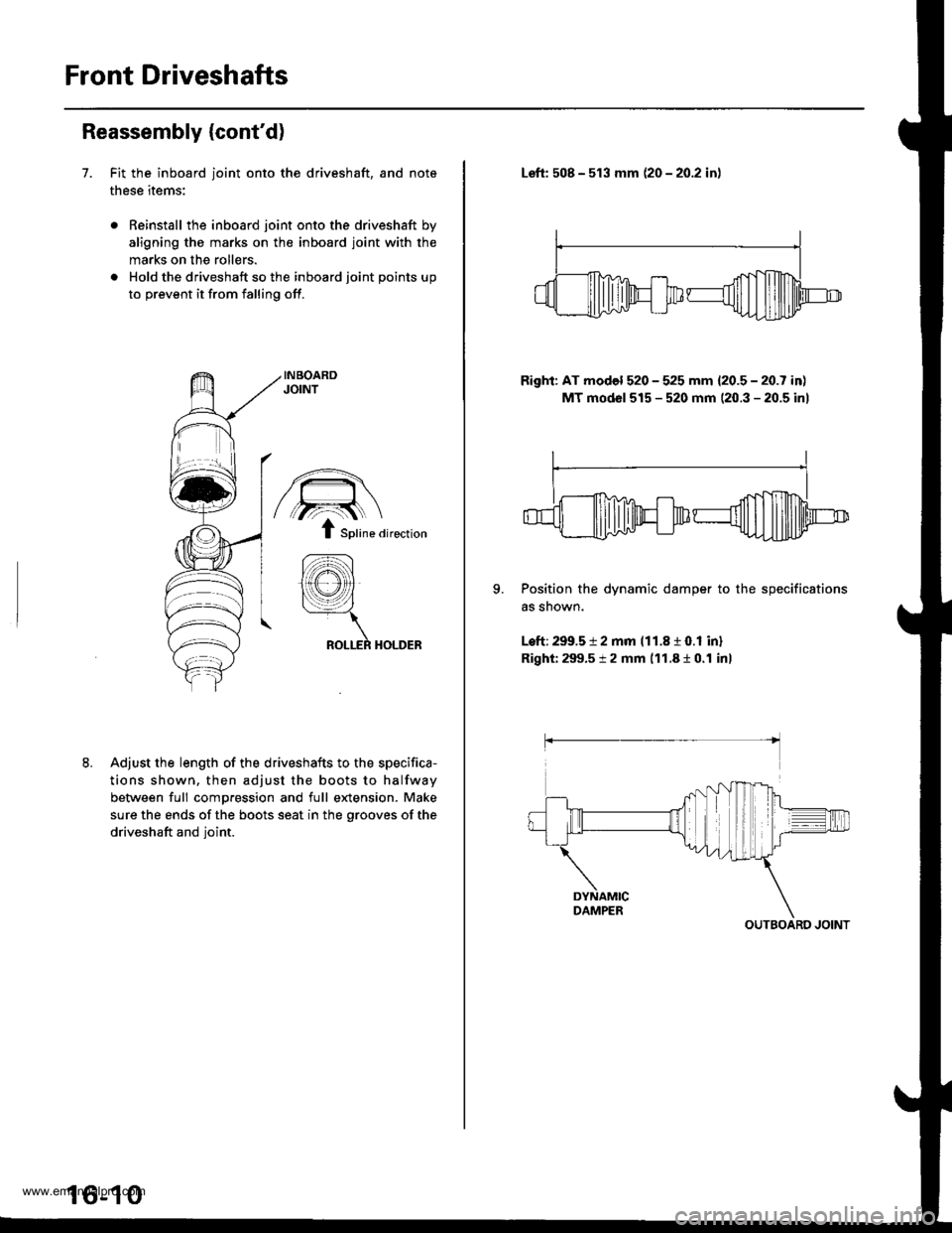
7. Fit the inboard joint onto the driveshaft, and note
these items:
Reinstall the inboard joint onto the driveshaft by
aligning ths marks on the inboard joint with the
marks on the rollers.
Hold the driveshaft so the inboard joint points up
to prevent it from falling off.
Adjust the length of the driveshafts to the specifica-
tions shown. then adjust the boots to halfway
between full compression and full e)dension. Make
sure the ends of the boots seat in the grooves of the
driveshaft and Ioint.
/€\
/,?:..�{ \
t Sptine airection
lffi
tYl:\
ROLLER HOLDER
16-10
Left: 508 - 513 mm 120 - 2O.2 inl
Right: AT model 520 - 525 mm {20.5 - 20.7 in)
MT mod6l 515 - 520 mm (20.3 - 20.5 inl
II
-flm+dm@
9. Position the dynamic damper to the specifications
as snown.
Left: 299.5 t 2 mm 111.8 r O.l inl
Right: 299.5 t 2 mm 111.810.1 inl
OUTBOARO JOINT
www.emanualpro.com
Page 826 of 1395
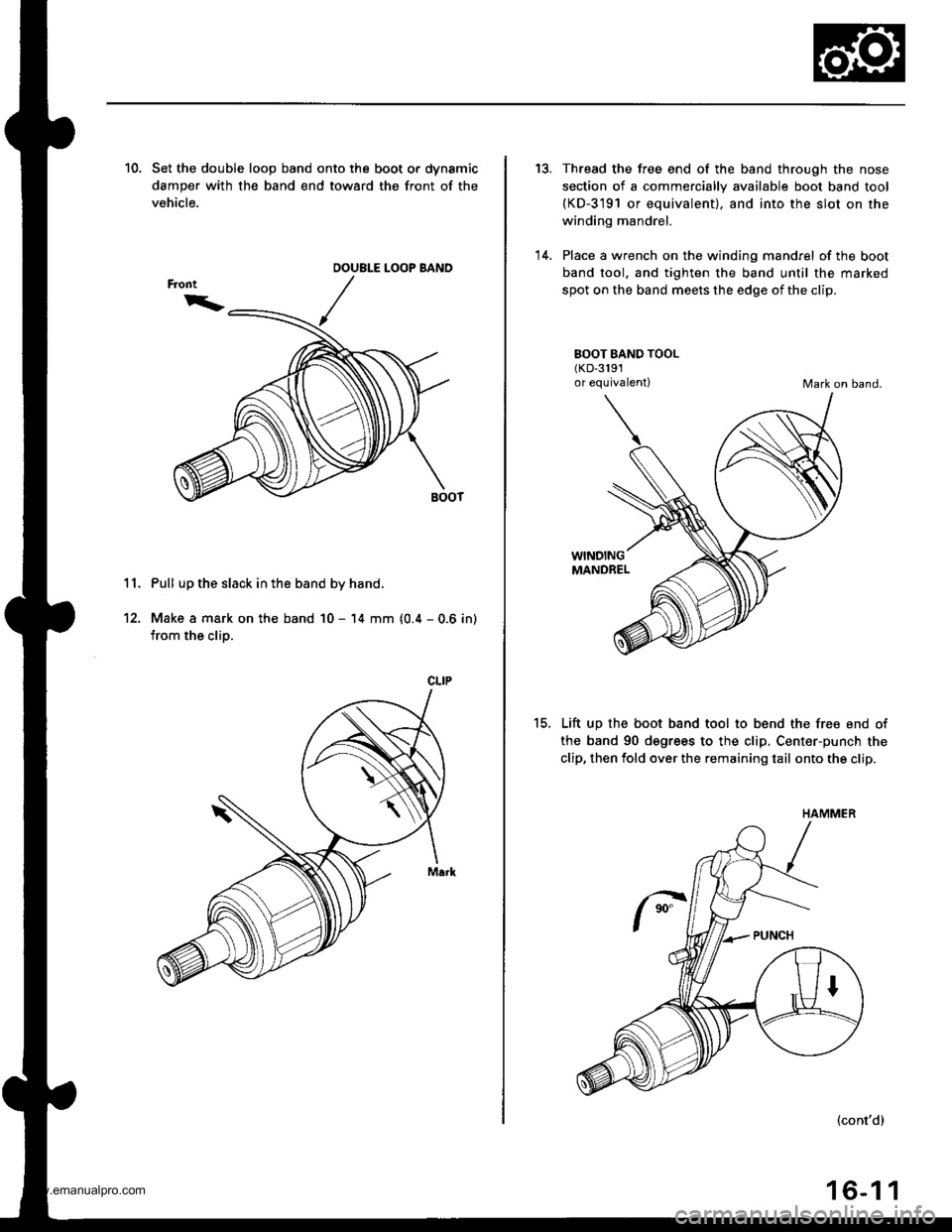
10. Set the double loop band onto the boot or dynamic
damper with the band end toward the front of the
vehicle.
11. Pull up the slack in the band by hand.
12. Make a mark on the band 10 - 14 mm (0.4 - 0.6 in)
from the clip.
OOUBLE LOOP BAND
CLIP
13.
'14.
Thread the free end of the band through the nose
section of a commercially available boot band tool(KD-3191 or equivalent). and into the slot on the
winding mandrel.
Place a wrench on the winding mandrel of the boot
band tool. and tighten the band until the marked
spot on the band meets the edge of the clip.
BOOT BAND TOOL(KD-3191
or equivalentlMark on band.
15.
WINDINGMANDREL
Lift up the boot band tool to bend the free end of
the band 90 degrees to the clip, Center-punch the
clip, then fold over the remaining tail onto the clip.
(cont'd)
16-1 1
HAMMER
www.emanualpro.com
Page 827 of 1395
Front Driveshafts
Reassembly (cont'd)
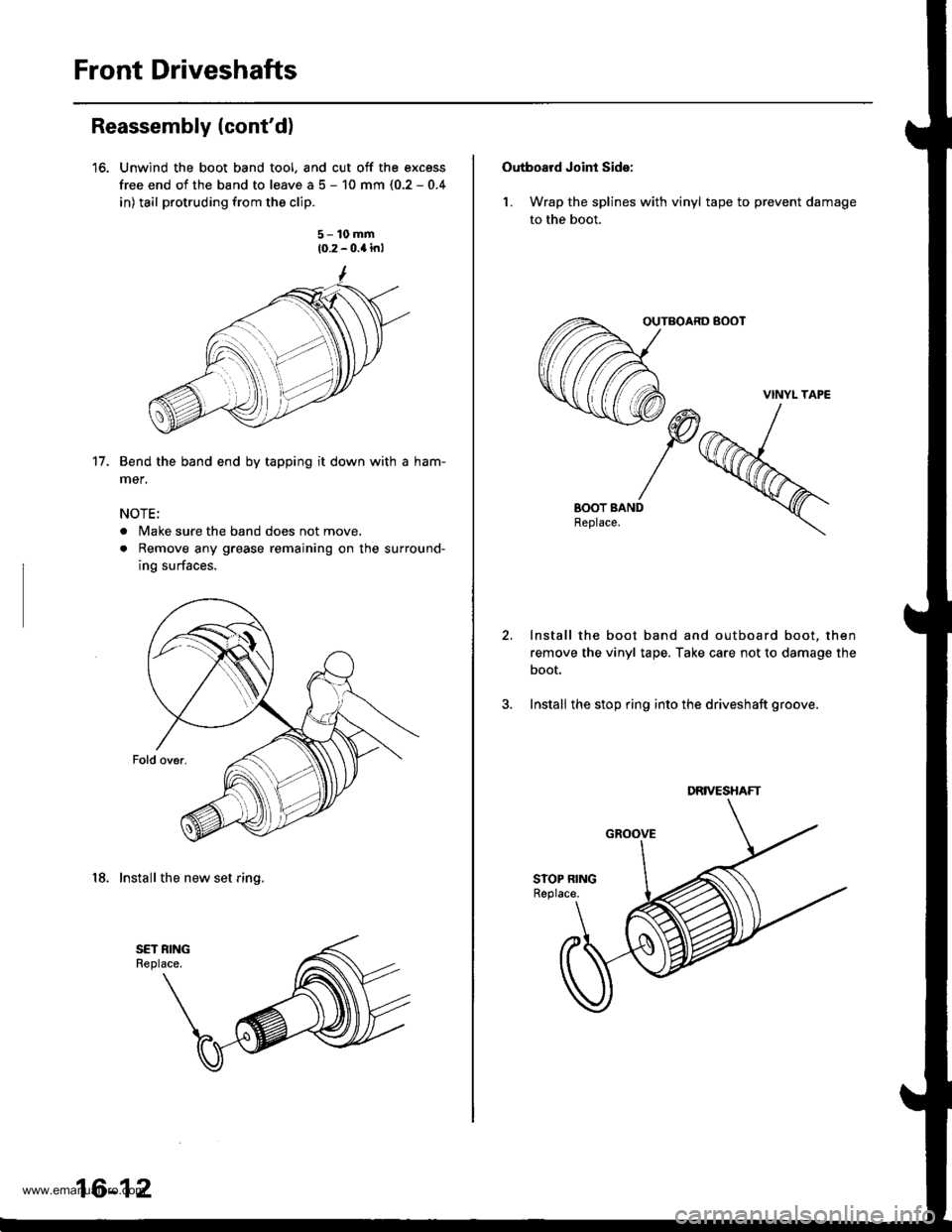
16. Unwind the boot band tool. and cut off the excess
free end of the band to leave a 5 - 10 mm (0.2 - 0.4
in) tail protruding from the clip.
5- 10 mm
10.2 - 0.4 in,
Bend the band end by tapping it down with a ham-
mer,
NOTE;
. Make sure the band does not move,
. Remove any grease remaining on the surround-
ing surfaces.
18, Install the new set ring.
17.
16-12
Outbosrd Joint Sids:
1. Wrap the splines with vinyl tape to prevent damage
to the boot.
OUTBOARD BOOT
2, Install the boot band and outboard boot, then
remove the vinyl tape. Take care not to damage the
boot.
3. Install the stop ring into the driveshaft groove.
VINYL TAPE
DRIVESHAFT
www.emanualpro.com
Page 828 of 1395
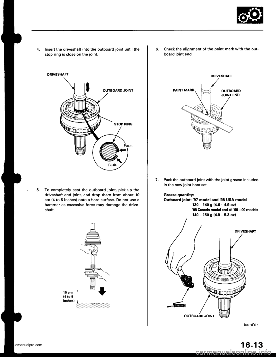
4. lnsert the driveshaft into the outboard ioint until the
stop ring is close on the joint.
DRIVESHAFT
To completely seat the outboard joint, pick up the
driveshaft and joint. and drop them from about 10
cm (4 to 5 inches) onto a hard surface, Do not use a
hammer as excessive force may damage the drive-
shaft.
i/,,,t| :l,r;;:,:.'i,,1;'/l
6. Check the alignment of the paint mark with the out-
board joint end.
DRIVESHAFT
1.Pack the outboard joint with the joint grease included
in the new joint boot set.
Grease quantity:
Outboard ioini: '97 model and '98 USA model
130 - 140 g {,1.6 - ,0.9 oz}'98 C8n8d8 modsl 8nd all '99 - 00 models
ll0 - tso g {i1.9 - 5.3 ozl
DRIVESHAFT
(cont'd)
16-13
www.emanualpro.com
Page 829 of 1395
Front Driveshafts
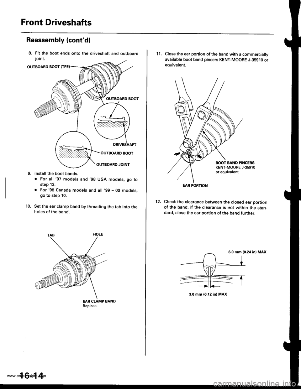
8. Fit the boot ends onto the driveshaft and outboard
lornt.
OUTBOARD BOOT fiPE)
OUTBOARD BOOT
OUTBOARD BOOT
Reassembly (cont'd)
Install the boot bands,
. For all '97 models and'98
step 13.
. For'98 Canada models andgo to step 10.
OUTBOARD JOINT
USA models, go to
all '99 - 00 models,
10. Set the ear clamp band by threading the tab into theholes of the band.
16-14
11. Close the ear portion of the band with a commercially
available boot band pincers KENT-MOORE J-35910 or
equivalent.
BOOT BAND PINCERSKENT.MOORE J-35910or equivalent
12.Check the clearance between the closed ear Dortionof the band, lf the clearance is not within the stan-dard, close the ear portion of the band further.
6.0 mm 10.24 in) MAX
3.0 mm {0.12 in} MAX
EAR PORTION
www.emanualpro.com
Page 830 of 1395
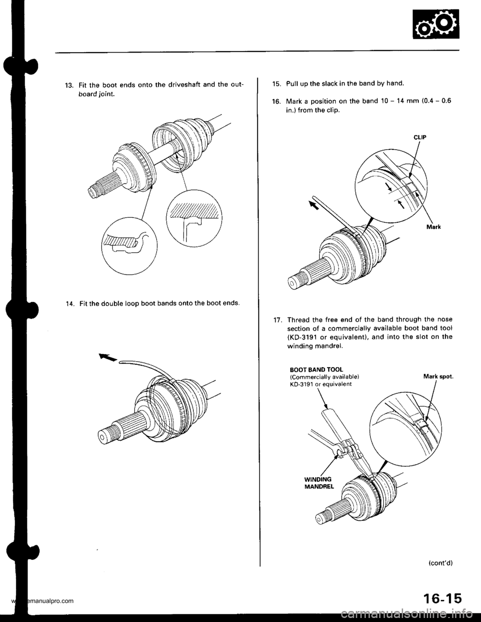
13. Fit the boot ends onto the driveshaft and the out-
board joint.
14. Fit the double looD boot bands onto the boot ends
15.
16.
Pull up the slack in the band by hand.
Mark a position on the band 10 - 14 mm (0.4 - 0.6
in.) from the clip.
Thread the free end of the band through the nose
section of a commercially available boot band tool
(KD-3191 or equivalentl, and into the slot on the
winding mandrel.
17.
BOOT BAND TOOL(Commercially available)KD-3191 or equivalentMark spot.
(cont'd)
16-15
CLIP
www.emanualpro.com