clearance HONDA CR-V 1997 RD1-RD3 / 1.G Workshop Manual
[x] Cancel search | Manufacturer: HONDA, Model Year: 1997, Model line: CR-V, Model: HONDA CR-V 1997 RD1-RD3 / 1.GPages: 1395, PDF Size: 35.62 MB
Page 27 of 1395
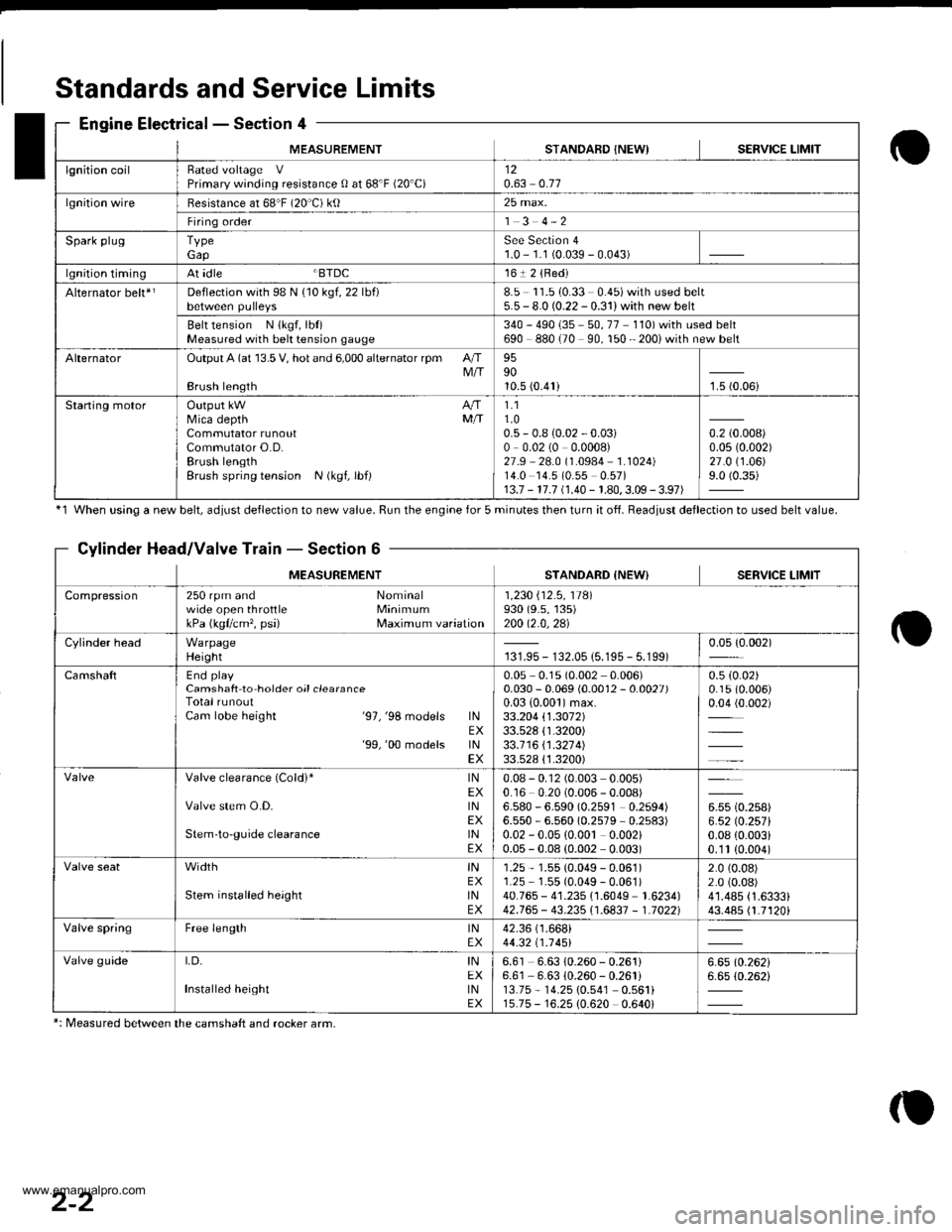
MEASUREMENTSTANDAFD INEWISERVICE LIMIT
lgnition coilRated voltage VPrimary winding resistance 0 at 68'F (20'C)120.63 0.77
lgnition wireBesistance at 68"F (20 C) ktl25 max.
Firing order1 3 4-2
Spark plugTypeGapSee Section 41.0 - 1.1 (0.039 - 0.043)
lgnition timingAt idle BTDC161 2 {Red)
Alternator belt*rDeflection with 98 N {10 kgf, 22 lbf)8.5 11.510.33 0.45)with used belt5.5 - 8.0 (0.22 - 0.31) with new belt
Belt tension N {kgf, lbt)Measured with bek tension gauge340 - 490 {35 - 50, 77 110) with used belt690 880 (70 90, 150 - 200i with new belt
AlternatorOutput A (at 13.5 V, hot and 6,000 alternator rpm AIIM/IBrush length
959010.5 (0.41)1.5 (0.06i
Staning motorOutput kW A/fMica depth MfiCommutator runoutCommutator O.D.Brush lengthBrush spring tension N (kgf, lbf)
1.11.00.5 - 0.8 {0.02 - 0.03)0,0.02 (0 0.0008)27.9 28.0 (1.0984 1.1024)14.0 14.5 (0.55 0.57)13.7 - 17.7 (1.40 - 1.80,3.09 - 3.97)
0.2 (0.008)
0.0s (0.002)
27.0 (1.06)
9.0 (0.35)
Standards and Service Limits
Engine Electrical - Section 4
'1 When using a new belt, ddiust deflection to new value. Run the engine for 5 minutes then turn it of{. Beadiust deflection to used belt value.
Cylinder Head/Valve Train - Section 6
MEASUREMENTSTANDARD {NEW} SERVICE LIMIT
Compression250 rpm and Nominalwide open throttle MinimumkPa (kgflcm'�, psi) Maximum variation
1 ,230 i'12 .5 , 11Al930 (9.s, 135)200 12.0,2al
Cylinder headWarpageHeight131.95 - 132.05 {5.195 - 5.199)0.05 {0.002)
CamshaftEnd playCamshaft to hoider oil clearanceTotal runoutCam lobe height '97,'98 models lNEX'99,'00 models lNEX
0.05 0.1s (0.002 0.006)0.030 - 0.069 (0.0012 - 0.0027)0.03 {0.001)max.33.204 \1.3072133.528 {1.3200)33.1 16 \1 .321 4)33.528 {'1.3200)
0.5 (0.02)
0.15 (0.006)
0.04 (0.002)
Valve clearance (Cold)* lNEXValve stem O.D. lNEXStem'to-guide clearance lNEX
0.08 - 0.12 (0.003 0.005)0.16 0.20 (0.006 - 0.008)6.580 - 6.590 (0.2591 0.2594)6.550 - 6.560 (0.2579 0.2s83)0.02 - 0.05 {0.00t 0.002)0.05 - 0.08 (0.002 0.003)
u* to.rutt6.52lO.257l0.08 {0.003i0.'1t (0.004)
width tNEXStem installed height lNEX
1.25 - 1.55 (0.049 - 0.061)1.25 1.55 (0.049 - 0.061)40.765 - 41.235 {1.6049 1.6234)42.765 - 43.235i'1.6837 - 1.70221
2.0 (0.08)
2.0 (0.08)
41.485 {1.6333}43.485 {1.7120i
Valve springFree length lNEX42.36 (1.668i
44.32 t1 .1 451
Valve guideI,D, INEXInstalled height tNEX
6.61 6.63 10.260 - 0.261)6.61 6.63 {0.260 - 0.261i13.75 - 14.25 10.541 0.561i15.75 - 16.25 {0.620 0.640i
6.6510.26216.65 (0.262i
*: Measured between the camshaft and rocker arm,
2-2
www.emanualpro.com
Page 28 of 1395
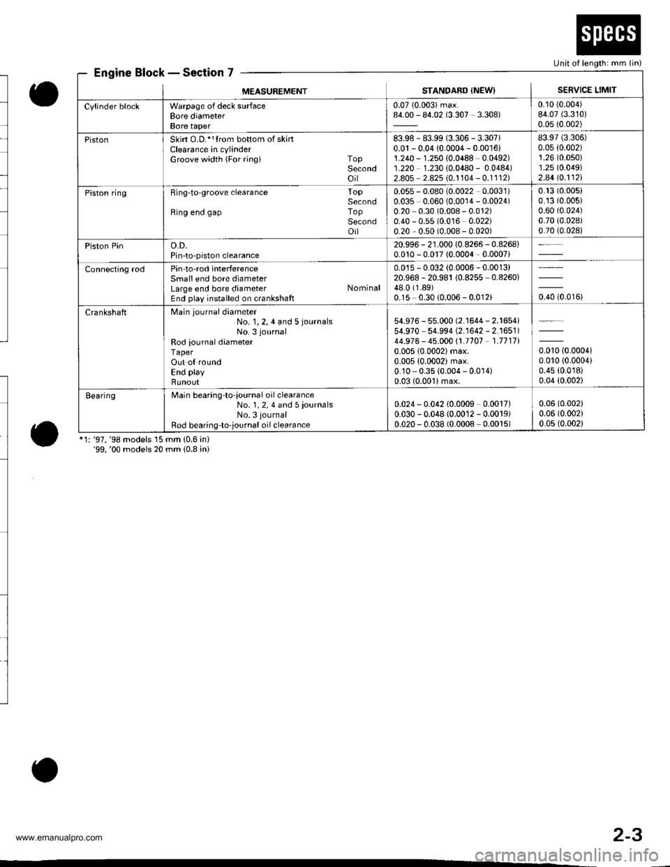
Engine Block - Section 7
o
o*1: '97,'98 models 15 mm (0.6 in)'99,'00 models 20 mm (0.8 ini
Unit of length: mm (in)
MEASUREMENTSTANDARD (NEWISERVICE LIMIT
Cylinder blockWarpage of deck surfaceBore diameterBore taper
0.07 (0.003) max.84.00 - 84.02 (3.307 3.308)0.10 (0.004)
84.07 (3.310)
0.05 (0.002)
PistonSkirt O.D.*1trom bottom of skartClearance in cylinderGroove width {For ringi TopSecondoil
83.98 - 83.99 (3.306 - 3.307)0.01 - 0.04 (0.0004 - 0.001611.240 - 1.250 {0.0488 - 0.0492)1.220 1.230 {0.0480 - 0.0484)2.805 2.825 10.1104 - 0.1112)
83.97 (3.306)
0.05 {0.002)1.26 (0.0s0)
1.25 (0.049)
2.44lo.112l
Piston ringRing-to'groove clearance ToPSecondRing end gap ToPSecondoil
0.055 - 0.080 (0.0022 0.0031)0.035 0.060 (0.0014 - 0.0024)0.20 0.30 (0.008 - 0.012)0.40 - 0.55 (0.016 0.022)0.20 - 0.50 (0.008 - 0.020)
0.13 (0.005)
0.13 (0.005)
0.60 (0.024)
0.70 (0.028)
0.70 (0.028)
Piston Pino.D.Pin-to-piston clearance
20.996 - 21.000 (0.8266 - 0.8268i0.010 - 0.017 (0.0004 - 0.0007)
Connecting rodPin-to-rod interferenceSmall end bore diameterLarge end bore diameter NominalEnd play installed on crankshaft
0.015 - 0.032 (0.0006 - 0.0013)20.968 -20.981 10.8255 -0.8260)
48.0 (1.89)
0.15 - 0.30 {0.006 - 0.012ioro to.oroi
CrankshaftMain journaldiameter
No. 1,2,4 and 5 iournalsNo. 3 journal
Rod iournal diameterTaperOut ol roundEnd play
Bunout
54.976 - 55.000 (2.'�l644 - 2.1654)54.970 54.994 (2.1642 - 2.1651)44.976 - 45.000 /.1.1707 - 1.711110.005 (0.0002)max.
0.005 (0.0002) max.0.10 - 0.35 (0.004 - 0.0 r 4)0.03 (0.001)max.
0.010 (0.00041
0.010 (0.0004)
0.45 (0.0r8)
0.04 (0.002)
BearingMain bearing-to-iournal oil clearanceNo. 1, 2, 4 and 5 iournalsNo. 3 journal
Rod bearing-to-,ournal oil clearance
0.024 - 0.042 10.0009 0.0017)0.030 - 0.048 (0.0012 - 0.0019)0.020 - 0.038 (0.0008 0.0015)
0.06 (0.002)
0.06 (0.002)
0.05 (0.002)
o
2-3
www.emanualpro.com
Page 29 of 1395
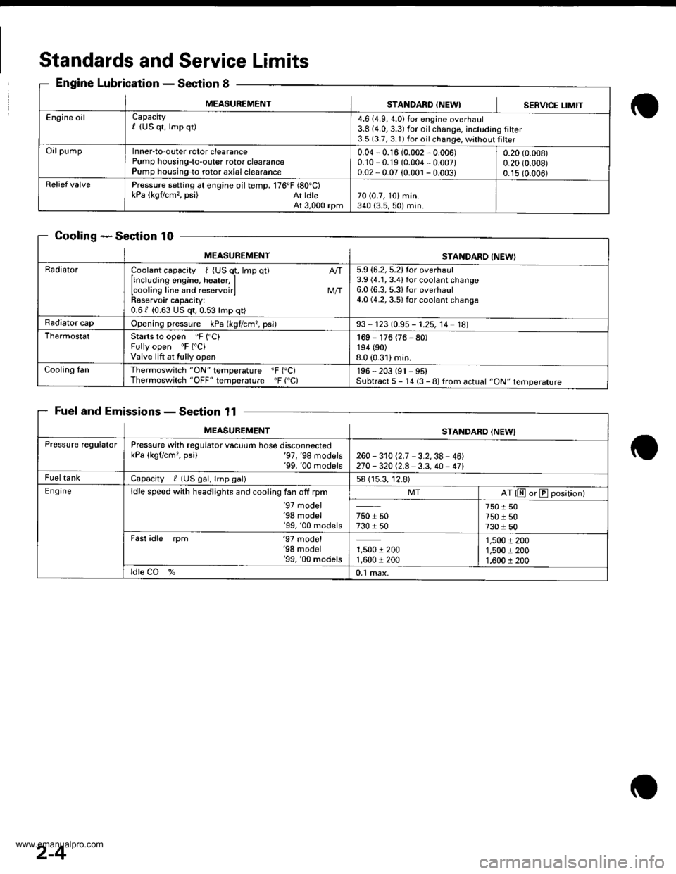
Standards andService Limits
Engine LubricationSection 8
CoolingSection 10
Fuel and EmissionsSection 11
MEASUREMENTSTANDARO {NEWISERVICE LIMIT
Engine oilCapacityf (US qt, lmp qt)4.6 (4.9, 4.0)Ior engine overhaul3.8 {4.0,3.3)for oilchange, including filter3.5 (3.7, 3.1) for oil change, without Iilter
OilpumpInner-to-outer rotor clearancePump housing-to-outer rotor clearancePump housing-to rotor axial clearance
0.04 - 0.16 (0.002 - 0.006)0.10 -0.19 (0.004 - 0.007)0.02 -0.07 (0.001 - 0.003i
0.20 (0.008)
0.20 (0.008)
0.15 (0.006)
Relief valvePressure setting at engine oil temp. 176'F (80'C)kPa (kgt/cm,, psi) At ldleAt 3,000 rpm70 (0.7, 10) min.340 {3.5,50) min.
MEASUREMENTSTANDARO INEW}
RadiatorCoolant capacity , (US q1, lmp qt)
llncluding engine, heater, ILcooling line and reservoirlReservoir capacity:0.61 (0.63 US qt,0.53lmp qt)
M/T
5.9 {6.2, 5.2}tor overhaul3.9 (4.1, 3.4ifor coolant change6.0 (6.3, 5.3ifor overhaul4.0 (4.2, 3.5) for coolant change
Radiator capOpening pressure kPa (kgf/cm?, psi)93 - 123 (0.95 - 1.25, 14 18)
ThermostatStarts to open 'F 1"C)Fully open 'F ("C)
Valve lift at tully open
169 - 176 (76 - 80)194 (90)
8.0 (0.31imin.
Cooling fanThermoswitch "ON" temperature "F {'C)Thermoswitch "OFF" temperature 'F ('C)196 - 203 (91 - 95)Subtract 5 - 14 (3 - 8) trom actual "ON" temperature
MEASUREMENTSTANDARD INEW}
Pressure regulatorPressure with regulator vacuum hose disconnectedkPa (kgflcm'�, psi) '97,'98 models'99, '00 rnodels260 - 31012.7 3.2,38- 46)270 -32012.8 3.3,40 - 471
FueltankCapacity / (US gal, lmp gal)58 (15.3, 12.8)
E ngineldle speed with headlights and cooling fan off rpm'97 model'98 model'99, '00 models
MTAT {E or E position)
750 r 50730 1 50
750 t 50750 r 507301 50
Fast idle rpm '97 model'98 model'99, '00 models1,5001 2001,600 r 200
1,5001 2001,5001 2001,600 r 200
ldle CO %0.1 max.
2-4
www.emanualpro.com
Page 30 of 1395
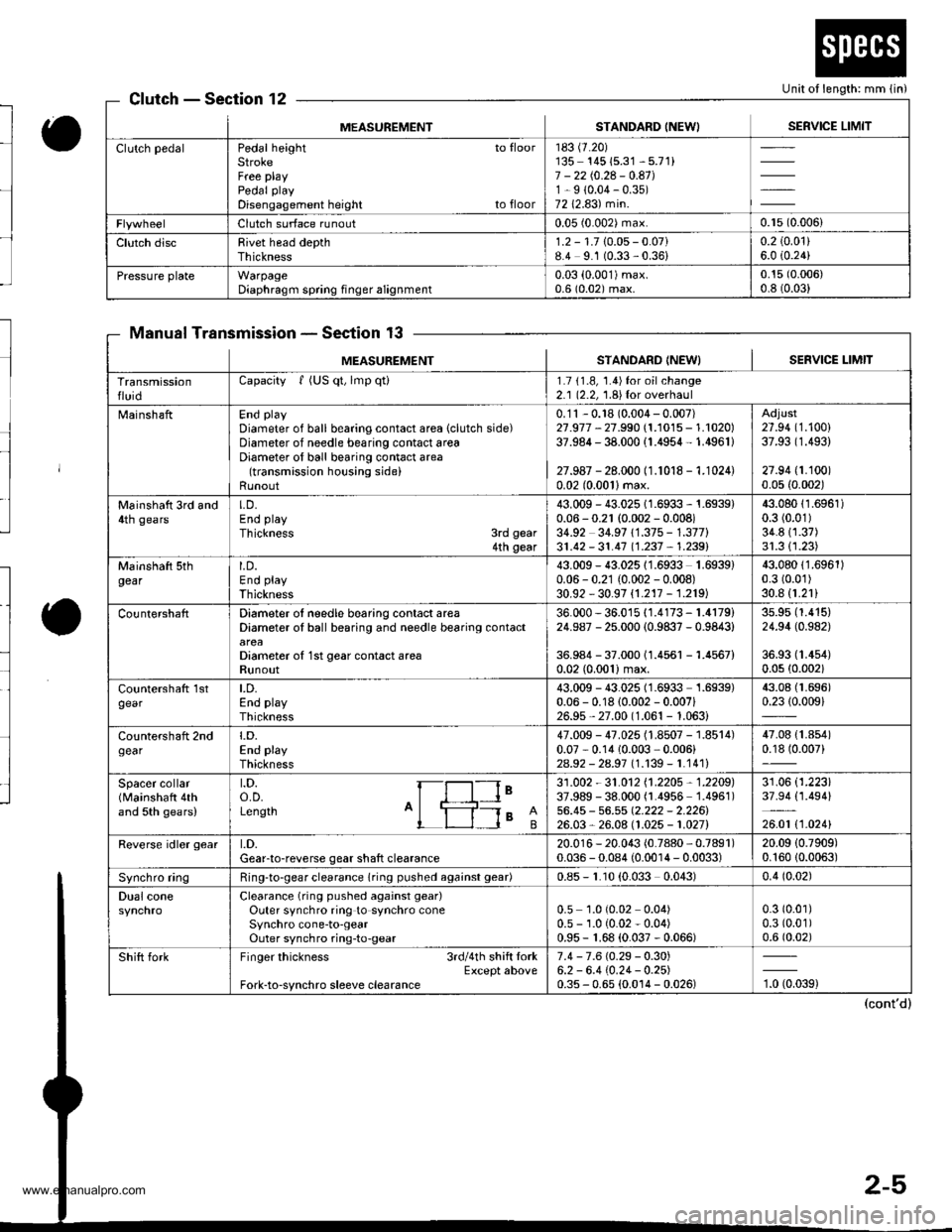
Unit of length: mm lin)ClutchSection 12
Manual TransmissionSection 13
MEASUREMENTSTANDARD INEWISERVICE LIMIT
Clutch pedalPedal height to floorStrokeFree playPedal play
Disengagement height to floor
183 (7.20)
135- 14515.31 - 5.71)7 - 2210.24 - 0.41J1-9 (0.04-0.35)
7212.83) min.
Clutch surface runout0.05 (0.002) max.0.r5 (0.006)
Clutch discRivet head depthThickness1.2 - 1.710.05- 0.07)8.4 9.1 (0.33,0.36)0.2 (0.01)
6.0 i0.24)
Pressure plateWarpageDiaphragm spring finger alignment0.03 (0.001)max.
0.6 (0.02) max.0.15 (0.006)
0.8 (0.03)
MEASUREM€NTSTANDARD INEW} I SERVICE I-IMIT
TransmissionfluidCapacity f (US qt, lmp qti1.7 11.8, 1.4)for oilchange2.1 (2.2, 1.8){or overhaul
MainshaftEnd play
Diameter of ball bearing contact area (clutch side)Diameter of needle bearing contact areaDiameter of ball bearing contact area(transmission housing side)Runout
0.'11 - 0.18 (0.004 - 0.007)27.977 - 27.990 (1.1015 - 1.1020)37.984 - 38.000 (1.4954- 1.4961)
27.987 - 28.000 (1.1018 - 1.1024)0.02 (0.0011max.
Adjust27.94 (1.100)
37.93 (1.493)
27.94 (1.100)
0.05 {0.002)
Mainshatt 3rd and4th gearsLD.End play
Thickness 3rd gear4th gear
43.009 - 43.025 1 1.6933 - 1.6939)0.06 - 0.21 (0.002 - 0.008)34.92 34.97 11.375 - 1.377)31.42 - 31.4'7 11.237 , 1.2391
43.08011.6961)0.3 (0.01)
34.811.37)31.311.23)
Mainshaft sthgearLD.End play
Thickness
43.009 - 43.02511.6933 1.6939)0.06 - 0.21 (0.002 - 0.008)30.92 - 30.97 {1.217 - 1.219)
43.08011.6961)0.3 (0.01)
30.8 (1.21)
CountershaftDiameter ol needle bearing contact areaDiameter oI ball bearing and needle bearing contact
Diameter o{ 1st gear contact areaRunout
36.000 - 36.015 {1.4173 - 1.4179)24.987 - 25.000 (0.9837 - 0.9843)
36.984 - 37.00011.4561 -1.4567)
0.02 (0.001)max.
3s.95 (1.415)
24.94 (0.982)
36.93 (1.4s4)
0.0s (0.002)
countershatt 1stgearLD.End playThickness
43.009 - 43.025 (1.6933 1.6939)0.06 - 0.18 (0.002 - 0.007i26.9s,27.00 (1.061 - 1.063)
43.08 (1.696)
0.2310.009)
Countershaft 2ndgeart.D.End playThickness
47.009 - 47.025 (1.8507 - 1.8514)0.07 - 0.14 10.003 ,0.006)
2As2 - 2a.97 l�1.139-1.1411
47.08 {1.854)0.18 (0.007)
Spacer collar(Mainshaft 4thand 5th gears)
t.D.o.D.Length A'ls I
le31 .002 - 31 .O12 11 .2205 , 1 .2205)37.989 - 38.000 (1.4956 1.4961)56.45 - 56.55 Q.222 - 2.226126.03,26.08 (1.025 - 1.027)
31.06 (1.223)
37.94 (1.494)
26.01 t1 .0241
Reverse idler geart.D.Gear-to-reverse gear shaft clearance20.01 6 - 20.043 (0.7880, 0.7891)0.036 - 0.084 (0.0014 - 0.0033)20.09 (0.7909)
0.16010.0063)
Synchro ringRing-to-gear clearance (ring pushed againsl gear)0.85 - r.10 (0.033 0.043)0.4 (0.02)
Dual coneClearance (ring pushed against gear)
Outer synchro ring to synchro coneSynchro cone-to-gearOuter synchro ring-to-gear
0.5 1.0 (0.02 0.04)0.5 - 1.0 (0.02 - 0.04)0.95 - 1.68 (0.037 - 0.066)
0.3 (0.01)
0.3 (0.01)
0.6 (0.02)
Shift forkFinger thickness 3rdl4th shift lorkExcept aboveFork-to-synchro sleeve clearance
7.4 - 7.6 (0.29 - 0.30)6.2 - 6.4 (0.24- 0.2s)0.35 - 0.65 (0.0't4 - 0.026)'t, torag)
www.emanualpro.com
Page 31 of 1395
Standards and Service Limits
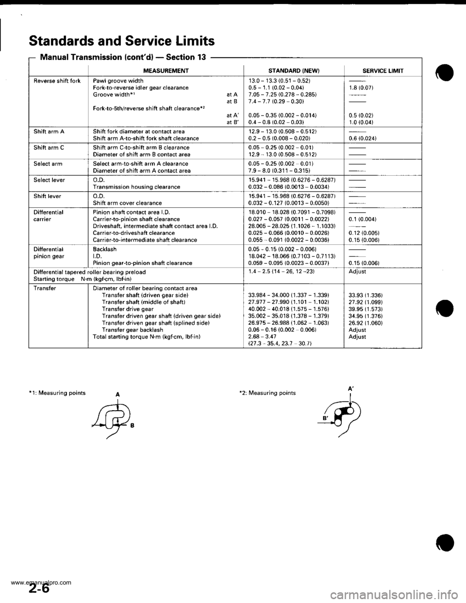
Manual Transmission {cont'd} - Section 13
11: fuleasuring points A
A
'Ay"
-l-...
_{-P)
A'*2: Measuring points
MEASUREMENTSTANDARO INEW) SERVICE LIMIT
Raverse shift IorkPawl groove widthFork-to-reverse idler gear clearanceGroove width*l at AatBFork-to-5th/reverse shift shaft clearance*'�
at B'
'13.0 - 13.3 (0.5'�j - 0.52)0.5 - 1.1 (0.02 - 0.04)7.O5 - 7.25 i.0.21 4 - 0.24517.4 -7.7 t0.29 0.301
0.05 - 0.35 (0.002 - 0.014)0.4,0.8 (0.02 0.03)
18 (0.07)
0.5 {0.02)1.0 (0.04)
Shift arm AShift fork diameter at contact areaShift arm A-to-shitt tork shaft clearance12.9 - 13.0 (0.508 - 0.512)0.2 - 0.5 (0.008- 0.020)0.6 {0.024i
Shift arm CShift arm C'to-shift arm B clearanceDiameter of shift arm B contact area0.05 0.25 (0.002 0.01)r2.9 - 13.0 (0.508 - 0.512)
Select armSelect arm'to-shift arm A clearanceDiameter of shift arm A contact area0.05 - 0.25 (0.002 0.01)7.9 - 8.0 (0.311 - 0.31s)
Select levero.D.Transmission housing clearance15.94r - 15.968 (0.6276 - 0.6287)0.032 - 0.086 (0.0013 - 0.0034)
Shift levero.D.Sh ift arm cover clearancer5.941 - 15.968 (0.6276 - 0.6287)0.032 - 0.127 (0.0013 - 0.0050)
DifferentialcarnerPinion shaft contact area LD.Carrier-to-pinion shaft clearanceDriveshaft, intermediate shatt contact area LD,Carrier-to-driveshaft clearanceCarrierto-interrnediate shaft clearance
18.010 18.028 (0.7091 - 0.7098)0.027 - 0.057 (0.0011 - 0.0022)28.005 - 28.025 (1.1026, 1.1033)0.025 - 0.066 (0.0010,0.0026)
0.055 - 0.091 10.0022 - 0.0036)
0.1 (0.004)
0.12 {0.005i0.15 (0.006i
Differentialpinion gearBacklasht.D.Pinion gearto-pinion shaft clearance
0.05-0.r5 {0.002 - 0.006)18.042 - 18.066 (0.7103 - 0.7113)0.059 - 0.095 10.0023 - 0.0037)oru ro.ooor
Ditferential tapered roll€r besring preloacStaning torque N.m (kgf.cm, lbl.ini
1.4 2.5i'14 26,12 -231Adjust
TransterDiameter of roller bearing contact areaTransler shaft {driven gear side}Translor shaft {middle of shaft)Transter drive gearTranslor driven gear shaft {driven gear side)Transter driven gear shaft (splined side)Trans{er gear backlashTotalstarting torque N.m (kgicm, lbiin)
33.984 - 34.000 (1.337 - 1.339)21.977 - 27.99011.101 1.102140.002 - 40.01811.575 - 1.576)35.002 - 35.01811.378 - 1.379)26.975, 26.988 (1.062 1.063)0.06 - 0.16 {0.002 0.006)2.64 3.41\21.3,35.4,23.1 30.t|
33.93 (1.336)
27 .92 (1 .O99)39.95 (1.573)
34.95 (1.376)
26.92 (1.060)
AdjustAdjust
2-6
www.emanualpro.com
Page 32 of 1395
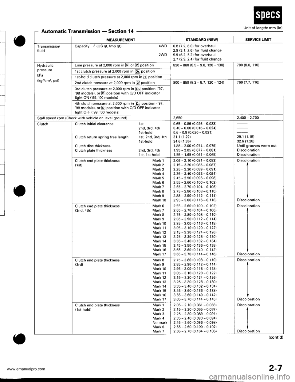
Unit of length: mm (in)Automatic TransmissionSection 14
MEASUREMENTSTANDARO INEW}SERVICE LIMIT
TransmissionfluidCapacity I {US qt, lmp q0 4WD
2WD
6.8 (7.2, 6.0) for overhaul2.9 (3.1, 2.6) for fluid change5.9 {6.2, 5.2)for overhaul2.7 {2.9, 2.4}for fluid change
Hydraulicpressure
kPa
(kgflcm'�, psi)
Line pressure at 2,000 rpm in LII or El position830 - 880 (8.5 - 9.0, 120 130)780 (8.0, 1'�t0)
1sl clutch pressure at 2,000 rpm in Da position
1st-hold clutch pressure at 2,000 rpm In l position
2nd clutch pressure at 2,000 rpm in El position800 - 850 (8.2 4.7,120 1241760 t7.7, 1101
3rd clutch pressure at 2,000 rpm in E position ('97,'98 models), or E position with O/D OFF indicatorlight ON ('99,'00 models)
4th clutch pressure at 2,000 rpm in gl position ('97,'98 models), or E position with O/D OFF indicatorlight oFF ('99,'00 models)
Stall speed rpm (Check with vehicle on level ground)2,5502,400,2,700
Clutch initial clearance 1st2nd,3rd,4th'lst-hold
Clutch return spring free length 1st, 2nd, 3rd, 4th'1st-hold
Clutch disc thicknessClutch plate thickness 2nd, 3rd, 4th1st, 1st-hold
0.65 - 0.85 (0.026 -0.033)
0.40 - 0.60 (0.016 - 0.024)0.5 - 0.8 (0.020 - 0.031)31 .1 11 .22)34.6 (1.36)
1.88 - 2.00 (0.074 - 0.079)'r.95 - 2.05 {0.077 0.081)'1.55- 1.65 (0.061 - 0.065)
29.1 (1.15)
32.6 (r.28)
Until grooves worn outDiscolorationDiscoloration
Clutch end plate thickness Mark 1(lsti Mark 2Mark 3Mark 4Mark 5Mark 6Mark 7Mark 8Mark IMark 10
2.05 - 2.r0 (0.081 - 0.083)2.15 2.20 (0.085 - 0.08712.25 2.30 (0.089,0.091)
2.35 2.40 {0.093 - 0.094}2.45 - 2.50 {0.096- 0.098}2.55 - 2.60 (0.100 - 0.102)2.65 - 2.70 (0.104 - 0.106)2.75 2.80 i0.108 - 0.110)2.85 - 2.9010.r 12 0.114)2.95 - 3.0010.116 0.118)
Discoloration
Discoloration
Clutch end plate thickness Mark 6{2nd, 4th) Mark 7Mark 8Mark 9Mark 10Mark 11lvlark 12Mark 13Mark 14Mark 15Mark 16Mark 17
2.55 2.60 10.100 - 0.102)2.65 2.70(0.104,0.106)2.75 - 2.80 (0.108 0.110)2.85 - 2.90 (0.112 -0.rr4)
2.95 3.00 (0.116-0.118)
3.05 - 3.10 (0.120 - 0.122)3.15 3.20 (0.124-0.126)
3.25 - 3.30 (0.128 0.130)3.35 - 3.40 (0. r32 - 0.134)3.45 - 3.50 (0.136 - 0.138)3.55 3.60 (0.140 - 0.142)3.65 - 3.70 (0.144 - 0.146)
Discoloration
Discoloration
Clutch end plate thickness Mark 8
{3rdi Mark IMark 10Mark 11Mark 12Mark 13Mark 14Mark 15Mark 16Mark 17
2.75 - 2.80 (0.108 0.110)2.85- 2.90 (0.112 - 0.114)2.95 - 3.00 (0.116 - 0.1'�j8)3.05 3.10 (0.120 - 0.122)3.15-3.20 {0.124 0.126)3.25 - 3.30 (0.128 - 0.r30)3.35 - 3.40 (0.132 - 0.r34i3.45 - 3.50 (0.136 - 0.138)3.55 - 3.60 {0.140 - 0.142)3.65 - 3.70 {0.144 - 0.r46)
Discoloration
Discoloration
Clutch end plate thickness Mark 1(1st hold) Mark 2Mark 3
No markMark 6Mark 7
2.05 2.10 (0.081 - 0.08312.r5 2.20 (0.085 - 0.087)2.25 - 2.30 {0.089 - 0.091}2.35 - 2.40 10.093 - 0.094i2.45 - 2.50 (0.096- 0.098i2.55 - 2.60 (0.r00 - 0.102)2.65 - 2.70 (0.r04 - 0.106)
(cont'd)
2-7
www.emanualpro.com
Page 34 of 1395
2-9
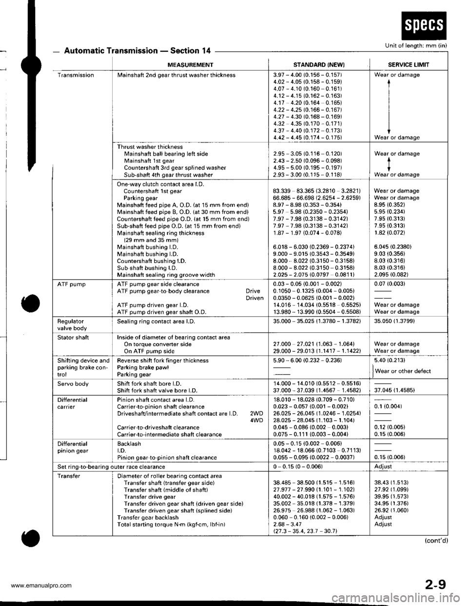
Automatic Transmission - Section 14
o
Unit of length: mm (in)
o
MEASUREMENTSTANDARD (NEWISERVICE LIMIT
TransmissionMainshaft 2nd gear thrust washer thickness3.97 - 4.00 10.156 - 0.157)4.02 - 4.05 {0.158 - 0.159)4.07 - 4.1010.160 0.161)4.12 - 4.15 (0.162 - 0.163)4.17 4.20 (0.164 0.165)4.22 - 4.25 10.166 - 0.167 )4.27 - 4.30 (0.168 - 0.169)4.32 4.35 (0.170-0.171)
4.37 - 4.40 (0.172 0.173)4.42 - 4.45 (0.174 - 0. r75)
I
I
IWear or damage
Thrust washer thicknessl'rainshaft ball bearing left sideMainshaft 1st gear
Countershaft 3rd gear splined washerSub-shaft 4th gear thrust washer
2.95 3.05 (0.116 0.120)2.43 - 2.50 (0.096 - 0.098)4.9s - 5.00 (0.195 - 0.197)2.93 - 3.00 (0.115 - 0.1181
Wear or damage
tIWear or damage
One-way clutch contact area LD.Countershaft 1st gearParking gearMainshaft feed pipe A, O.D. (at 15 mm trom end)Mainshaft feed pipe B, O.D. (at 30 mm from end)Countershaft teed pipe O.D. lat 15 mm from end)Sub-shaft feed pipe O.D. (at 15 mm from end)Mainshatt sealing ring thickness(29 mm and 35 mm)Mainshaft bushing I.D.Mainshaft bushing l.D.Countershaft bushing l.D.Sub shatt bushing LD.Mainshaft sealing ring groove width
83.339 83.365 (3.2810 3.2821)66.685 - 66.698 (2.6254 - 2.6259)8.97 - 8.98 (0.353 - 0.354)5.97 5.98 {0.2350 - 0.2354)7.97 - 7.98 (0.3138 - 0.3142)7.97 ,7.98 (0.3138 - 0.3142)1.87 - 1.97 (0.074-0.078)
6.018 - 6.030 (0.2369 - 0.2374)9.000 - 9.015 (0.3543 - 0.3549)8.000 - 8.022 (0.3150-0.3158)
8.000 - 8.022 (0.3150 0.3158)2.025 - 2.075 (0.0797 0.0811)
Wear or damageWear or damage8.95 (0.352)
5.95 (0.234)
7.95 (0.313)
7.95 {0.313)1 .42 $.O72)
5.045 (0.2380)
9.03 (0.356)
8.03 (0.316)
8.03 (0.316)
2.095 (0.082)
ATF pumpATF pump gear side clearanceATF pump gear'to body clearance DriveDrivenATF pump driven gear LD.ATF pump driven gear shaft O.D.
0.03 - 0.05 (0.001 - 0.002)0.1050 0.1325 (0.004, 0.005)0.0350 - 0.0625 10.001 - 0.002)14.016* 14.034 (0.5518 0.5525)13.980 - 13.990 {0.5504 0.5508)
0.0710.003)
Wear or damageWear or damage
Regulatorvalve bodySealing ring contact area l.D,35.000 35.025 {1.3780 - 1.3782)35.050 (1.3799)
Stator shaftInside of diameter oI bearing contact areaOn torque convener sideOn ATF pump side2't .o00 27 .021 I '1 .063 , 1 .064)29.000 - 29.01311.r417 1.1422)Wear or damageWear or damage
Shifting device andparking brake con'trol
Reverse shitt fork finger thicknessParking brake pawl
Parking gear
5.90 - 6.00 {0.232,0.236)5.40 (0.213)
lWear or other defect
Servo bodyShift fork shatt bore l.D.Shift fork shatt valve bore l.D.14.000 - 14.010 (0.55'�l2 - 0.5516)37.000 - 37.039 (1.4567 - 1.4582)37.045 (1.4585)
DifferentialcarrierPinion shaft contact area LD.Carrierto-pinion shaft clearanceDriveshafvintermediate shaft contact are l.D. 2WD4WDCarrier to driveshalt clearanceCarrier-to-intermediate shaft clearance
'18.010 - 18.028 10.709 - 0.710)0.023 - 0.057 {0.001 - 0.002}26.025 - 26.045 (1.0246 - 1.0254)28.025 - 28.045 (1.103 - 1.104)0.045 - 0.08610.002 0.003)0.075 - 0.111 10.003- 0.004)
0.r {0.004)
0.12 (0.005)
0.15 (0.006)
Differentialprnron gearBacklasht.D.Pinion gear'to-pinion shaft clearance
0.05 - 0.15 (0.002 - 0.006)18.062 - 18.066 (0.7103 - 0.7113)0.055 - 0.095 10.0022 - 0.0037)otu to.oout
Set ring-to-bearing outer race clearance0 0.15 (0 - 0.006)Adjust
TransferDiameter of roller bearing contact areaTransfer shaft (transfer gear side)Transfer shaft (middle of shaft)Transfer drive gearTransfer driven gear shaft {driven gear side)Transfer driven gear shaft {splined side)Transfer gear backlashTotalstarting torque N.m (kgf.cm, lbf.in)
38.485 38.500 (1.515 - 1.516)27 .917 - 21 .990 |.1.101 - 1.102)40.002 - 40.018 (1.575 - 1.576)35.002 35.018 (1.378 - 1.379)26.975 26.988 (1.062 -'�l.063)
0.060 0.160 (0.002 - 0.006)2.64 - 3.41127.3 - 35.4,23.1 30.71
38.43 (1.513)
27.92 (1.099)
39.95 (1.573)
34.95 (1.376)
26.92 (1.060)
AdiustAdiust
(cont'd)
www.emanualpro.com
Page 36 of 1395
to
l
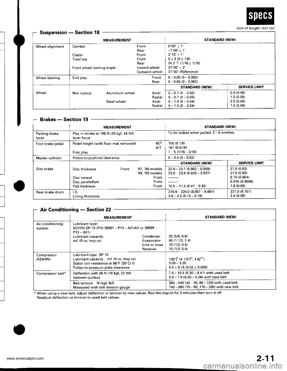
SuspensionSection 18
BrakesSec'tion 19
Air ConditioningSection 22
* When using a new belt, adjust deflection or tension to new values. Run the engine for 5 minutes then turn it off.
Readjust deflection or tension to used belt values.
o
Unit of length: mm {in)
MEASUREMENTSTANDARD {NEW)
WheelalignmentCamber FrontRearCaster FrontTotaltoe FrontnearFront wheel turning angle Inward wheelOutward wheel
0"00' 1 1'- 1"00' 1 1'2"10' ! 1"0J3(011/8)rN 2 ri (1/161 1/r6)37"00' ! 231'30'(Referencei
Wheel bearingEnd playFrontRear0 - 0.05 {0- 0.002}0 - 0.05 (0 0.002i
Rim runout Aluminum wheel AxialBadialSteelwheel AxialRadial
STANOARD (NEW)SERVICE LIMIT
0 - 0.7 (0 0.03)0,0.7 (0 - 0.03)0 1.0 (0 - 0.04)0 - 1.0 {0 - 0.04)
2.0 (0.08)'r.5 {0.06)2.0 {0.08)1.s (0.06)
MEASUREMENTSTANDARD INEWI
Parking brakeleverPlay in stroke at 196 N (20 kgf,44lbf)lever force
To be locked when Dulled: 2 - 6 notches
Foot brake pedalPedal height (with tloor mat removed)
Free playNT
155 (6 1/8)161 (6 5/16)1 5 (1/16 - 3/16)
Master cylinderPiston-to-pushrod clearance0 - 0.4 (0- 0.02)
Disc brakeDisc thickness Front '97, '98 models'99, '00 modelsDisc runoutDisc parallelismPad thickness
FrontFrontFront
STANDARD {NEW'SERVICE LIMIT
22.9 - 23.1 (0.902 - 0.909)23.6 23.8 (0.929 - 0.937)
10.5 - 11.5 (0.4'�t 0.45)
21.0 (0.83)
21.0 (0.83)
0.10 {0.004)0.015 (0.0006)
1.6 (0.06)
Rear brake drumLD.Lining thickness
2r9.9 220.0 (8.657 - 8.661)3.9 - 4.5 (0.15 - 0.18)221.O 8.70112.0 (0.08)
MEASUREMENTSTANDARD {NEWI
Air conditioningLubricant type:KEIHIN SP 10 (P/N 38897 - Pl3 - A01AH or 38899 -
Pl3 - A01)Lubricant capacity Condensermf {floz, lmp oz) EvaporatorLine or hoseReceiver
25 (5/6,0.9)
40 {1 1/3, 1.4)10 {1/3,0.4)10(.]/3,0.4)
Compressor(KEIHIN)Lubricant type: SP 10Lubricant capacity ml ({l 02, lmp oz}Stator coil resistance at 68'F (20"C) OPulley-to-pressuae plate clearance
130'3'{4 1fi'3o, 4.6;"}3.05 - 3.350.51 0.15 (0.02 1 0.006)
Compressor belt*Deflection with 98 N (10 kgl,22lblibetween pulleys7.5 - 10.5 {0.30 - 0.41) with used belt5.0 - 7.0 (0.20 - 0.28) with new belt
Belt tension N (kgf, lbf)Measured with belt tension gauge390 - 540 (40 55,88-120)withusedbelt740 - 880 {75 90, 170 - 200) with new belt
2-11
www.emanualpro.com
Page 114 of 1395
Cylinder Head/Valve Train
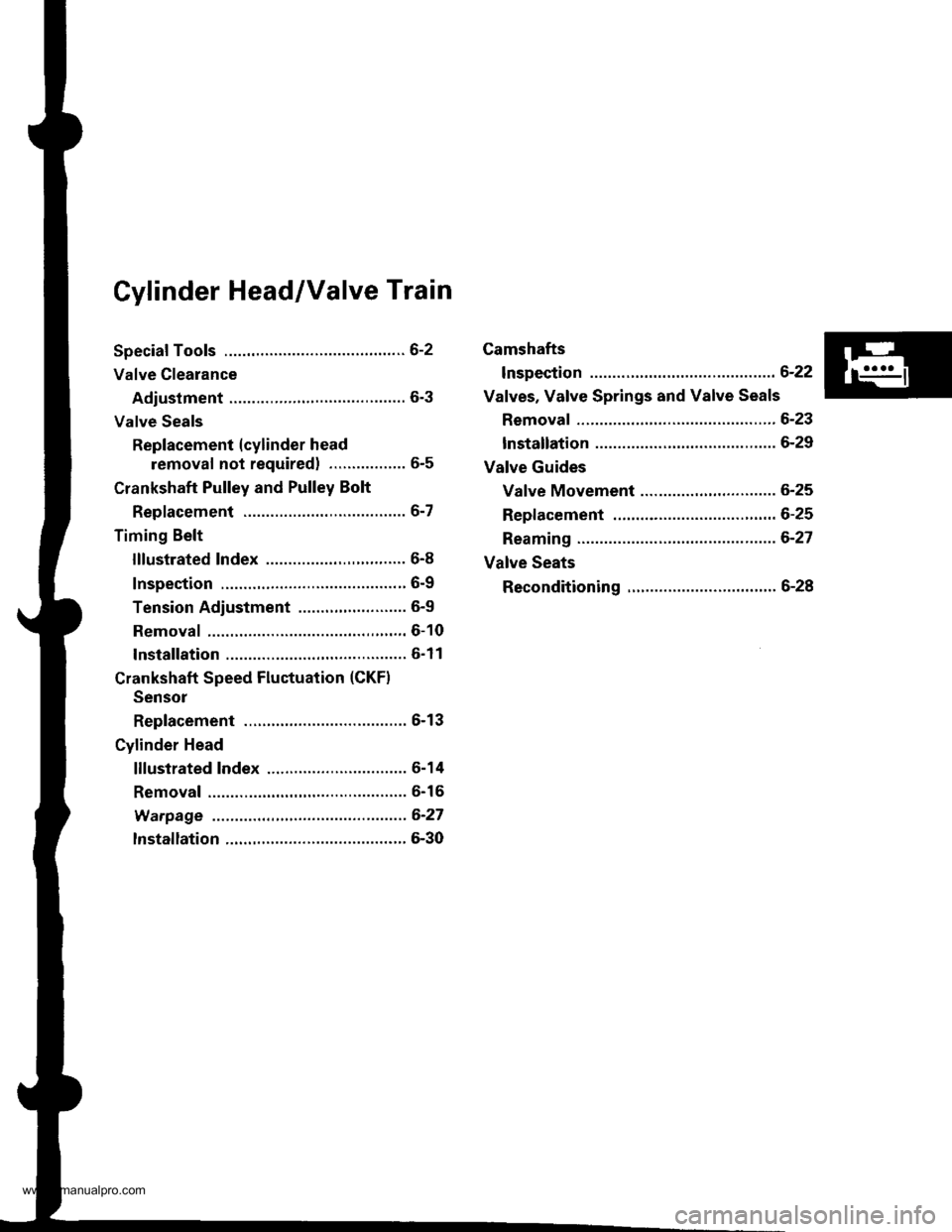
Speciaf Tools .............6-2
Valve Clearance
Adiustment ............6-3
Valve Seals
Replacement (cylinder head
removal not requiredl ................. 6-5
Crankshaft Pulley and Pulley Bolt
Replacement .........6-7
Timing Belt
I llustrated lndex ............................... 6-8
Inspection ............., 6-9
Tension Adjustment ........................ 6-9
Removal ...........,..... 6-10
lnstallation .............6-11
Crankshaft Speed Fluctuation (CKFI
Sensor
Replacement .........6-13
Cylinder Head
lllustrated lndex ............................... 6-14
Removal .................6-16
Warpage ................6-27
lnstallation ............. 6-30
Camshafts
lnspection ..............6-22
Valves, Valve Springs and Valve Seals
Removal ................, 6-23
lnstallation ............. 6-29
Valve Guides
Valve Movement ............,,,,.,............ 6-25
Replacement .........6-25
Reaming .................6-27
Valve Seats
Reconditioning ......6-28
www.emanualpro.com
Page 116 of 1395
Valve Clearance
Adiustment
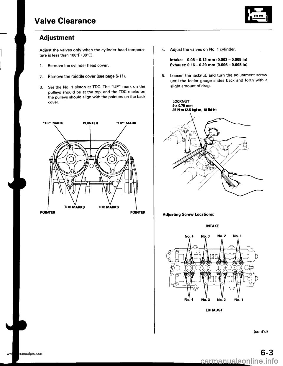
Adjust the valves only when the cylinder head tempera-
ture is less than 100"F (38"C).
1. Remove the cylinder head cover.
Remove the middle cover (see page 6-11).
Set the No. 1 piston at TDC. The "UP" mark on the
pulleys should be at the top, and the TDC marks on
the pulleys should align with the pointers on the back
POINTERPOINTER
Adjust the valves on No. 1 cylinder.
Intake: 0.08 - 0.12 mm (0.003 - 0.005 inl
Exhaust: 0.16 - 0.20 mm (0.006 - 0.008 in)
Loosen the locknut, and turn the adiustment screw
until the feeler gauge slides back and forth with a
slight amount of drag.
LOCI(NUT9 x 0.75 m.n
Adiusting Screw Locations:
INTAKE
No.4 No.3 No.2
(cont'd)
6-3
25 N.m 12.5 kgf.m, 18lbf.ft)
EXHAUST
No. 1
www.emanualpro.com