iacv HONDA CR-V 1997 RD1-RD3 / 1.G Workshop Manual
[x] Cancel search | Manufacturer: HONDA, Model Year: 1997, Model line: CR-V, Model: HONDA CR-V 1997 RD1-RD3 / 1.GPages: 1395, PDF Size: 35.62 MB
Page 269 of 1395

Powertrain Control Module Terminal Arrangement -'97 Model
FCM CONNECTOR A (32P)NOTE: Standard battery voltage is 12 V.
Wire side of lemale terminals
f€rminalnumlreJWirecolor
Telminalnama
DescriptionSignal
YELlNJ4 (No.4 FUELINJECTOR)Drives No. 4 {uel injector.With engine running: duty controlled
2BLUlNJ3 (No.3 FUELINJECTOR)Drives No. 3luel injector.
REDlNJ2 {No.2 FUELINJECTOR)Drives No.2 tuel injector.
BRNlNJl (No. l FUELINJECTOR)Drives No. 1 fuel injector.
5BLK WHTSO2SHIC (SECONDARY
HEATED OXYGEN SENSOR HEATER CONTROL)
D ves secondary heated oxygensensor heater.With ignition switch ON {ll): battery voltageWith fully warmed up engino running: dutycontrolled
6BLKAr'YHT
PO2SHTC (PRIMARY
HEATED OXYGENSENSOR HEATERCONTROL}
Drives primary heated oxygensensor heater,With ignition switch ON lll): battery voltagewith fully warmed up engine running: dutycontroll6d
I8RN/BLKLGl (LOGIC GROUND}Ground forthe PCM control circuit.Less than 1.0 V at all times
10BLKPG1 lPOWER GROUND}Ground for the PCM power circuit.
l1YEUELKIGPl lPOWER SOURCE}Power source for the PCM controlcircuit.
With ignition switch ON (ll): battery voltageWith ignition switch OFF: 0 V
12BLI(BLUIACV {IDLE AIRCONTROL VALVE}Drives IACV.With €ngine running: duty controlled
REDryEL
PCS (EVAP PURGECONTFOL SOLENOIDVALVE)
Drives EVAP purge controlsolenoid valve.
With engine running, engine coolantbelow 154'F (68"C): battery voltageWith engine running, engine coolantabove 154"F (68"C): duty controlled
16GRN/VELFLR (FUEL PUMP RELAY)Drives Iuel pump relay.0 V for two seconds after turning ignition
switch ON lll), then battery voltage
118LI(REDACC (A,/C CLUTCHRELAY}Drives Ay'C clutch relay.With comoressor ON: 0 VWith compressor OFF: baftery voltage
18GRN/ORNMIL (MALFUNCTION
INDICATOR LAMP}Drives MlL.With MIL turned ON: 0 VWith MIL turned OFF: baftery voltage
19*WHT/GRNALTC (ALTERNATOR
CONTROL}Sends alternator control signal.With tully warmed-up engine running:
battery voltageDuring driving with smallelectrical load:0 '
20YEUGRNICM (IGNITION CONTROLMODULE)Sends ignition pulse.With ignition switch ON (ll): baftery voltageWith engine running: pulses
22BRN/BLKLG2 (LOGIC GROUND}Ground tor the PCM control circuit.Less than 1.0 V at alltimes
23BLKPG2 {POWER GROUND}Ground lor the PCM power circuit.
24YEUBLKIGP2 {POWER SOURCE}Power source for the PCM controlcircuit.
With ignition switch ON (ll): battery voltage
With engine switch OFF: 0 V
27GRNFANC (RADIATOR FANCONTROL)Drives radiator {an relay.With radiator fan running: 0 VWith radiator fan stopped: baftery voltage
*: USA
{cont'd)
11-67
www.emanualpro.com
Page 274 of 1395

Troubleshooting
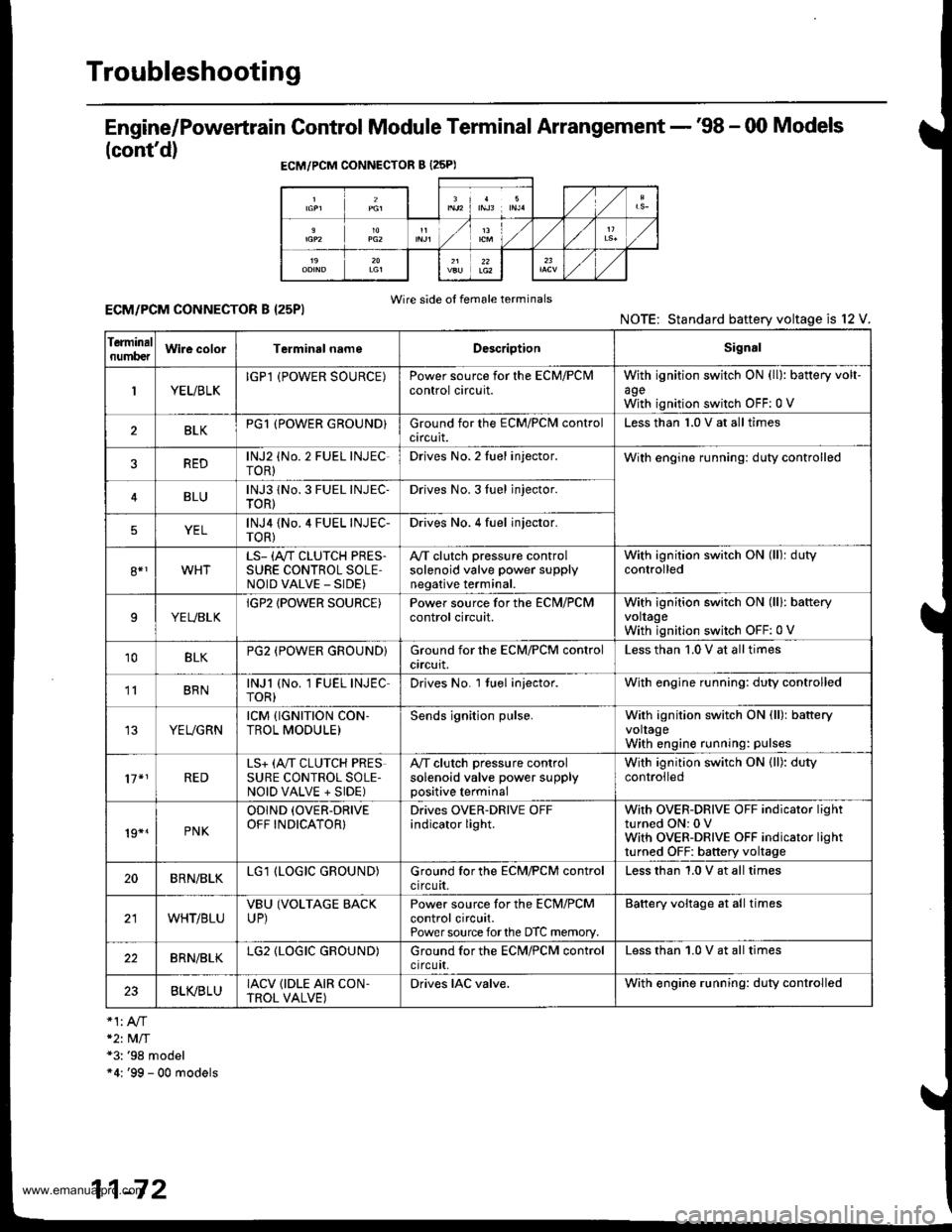
Engine/Powertrain Control Module Terminal Arrangement - '98 - 00 Models
(cont'd)
ECM/PCM CONNECTOR B {25PI
Wire side of female terminalsECM/PCM CONNECTOR B I25PI
*2t MlT*3: '98 model"4: '99 - 00 models
NOTE: Standard baftery voltage is l2
Ierminalnumb€tWire colorTerminsl nameDescriptionSignal
1YEUBLKIGPl (POWER SOURCE)Power source for the ECM/PClvlcontrol circuit.withagewith
ignition switch ON (ll): battery volt-
ignition switch OFF:0 V
BLKPG1 (POWER GROUND}Ground for the ECM/PClvl controlcircuit.Less than 1.0 V at all times
REDlNJ2 (No. 2 FUEL INJEC-roR)Drives No. 2 Iuel injector.With engine running: duty controlled
BLUlNJ3 1No. 3 FUEL INJEC-TOR)Drives No. 3Iuel jnjector.
YELlNJ4 {No.4 FUEL INJEC-TOR)Drives No. 4 fuel injector.
8*1WHTLS- (A"/T CLUTCH PRES.SURE CONTROL SOLE,NOID VALVE _ SIDE)
A,/T clutch pressure controlsolenoid valve power supplynegative terminal.
With ignition switch ON (ll): dutycontrolled
9YEUBLKIGP2 IPOWER SOURCE)Power source for the ECN,I/PCMcontrol circuit.With ignition switch ON (lll: bafteryvoltageWith ignition switch OFF:0 V
10BLKPG2 (POWER GROUND}Ground for the ECM/PCM controlcrrcurt.Less than '1.0 V at all times
' BRNlNJl (No. 1 FUEL INJECTOR)Drives No. l tuel injector.With engine running: duty controlled
YEUGRNrcM {rGNrTroN coN-TROL MODULE)Sends ignition pulse.With ignition switch ON (ll): batteryvoltageWith engine running: pulses
17*1REDLS+ (A,,IT CLUTCH PRESSURE CONTROL SOLE-NOID VALVE + SIDE)
A,/T clutch pressure controlsolenoid valve power supplypositive terminal
With ignition switch ON (ll): dutycontrolled
19*.PNK
ODIND (OVER-DRIVE
OFF INDICATOR}Drives OVER-DRIVE OFFindicator light.With OVER-DRIVE OFF indicator lightturned ON: 0 VWith OVER-DRIVE OFF indicator lightturned OFF: battery voltage
20BRN/BLKLG1 (LOGIC GROUND)Ground for the ECM/PCM controlcircuit.Less than 1.0 V at all times
WHT/BLUVBU (VOLTAGE BACKUP)Power source for the ECM/PCMcontrol circuit.Power source forthe DTC memory.
Battery voltage at all times
22BRN/BLKLG2 (LOGIC GROUND)Ground for the ECN4/PCM controlctrcutt,Less than 1.0 V at all times
23BLVBLUIACV {IDLE AIR CON.TROL VALVE)Drives IAC valve.With engine running: duty controlled
11-72
www.emanualpro.com
Page 356 of 1395

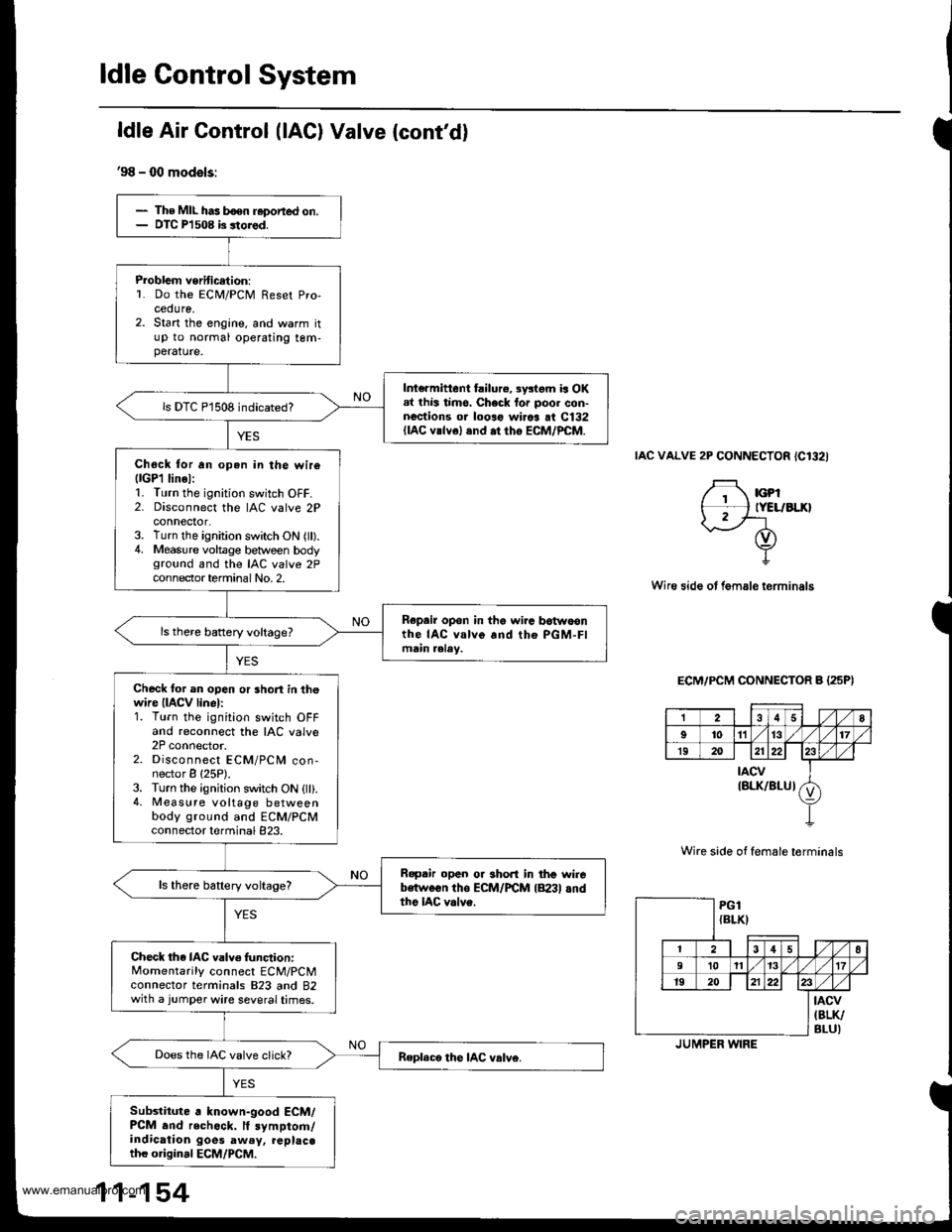
The MIL has boen r.ported on.DIC Pl 508 b 3tored.
Problem veritication:L Do the ECM/PCM Reset Pro-cedure.2. Start the engine, and warm itup to normal operating tem-perature.
Int€rmittent failure, systom is OKal lhis timo. Check lor poor con-nections or looro wirca at C132(lAc vrlvel and .t rho EcM/PcM.
ls DTC P1508 indicated?
Chock tor an open in the wir6llGPl linel:1. Turn the ignition switch OFF.2. Disconnect the IAC valve 2Pconnector,3. Turn the ignition switch ON (ll).4. Measure voltage between bodyground and the IAC valve 2Pcon nector termina I No, 2.
Repair opon in the wira botwoonthe IAC valve and tho PGM-FImain aalay.
Check tor an open or short in thewire (IACV linel:1. Turn the ignition switch OFFand reconnect the IAC valve2P connector.2. Disconnect ECM/PCM con-nector B {25P).3. Turn the ignition switch ON {ll}.4. Measure voltage betweenbody ground and ECM/PCMconnector terminal 823.
Ropair open or short in thg wirebetween tho ECM/FCM lB23l andthe IAC valve.
ls there battery voltage?
Check the IAC valve func,tion:Momentarily connect ECM/PCMconnector terminals 823 and 82with a jumper wire several times.
Does the IAC valve click?
Subslitute . known-good ECM/PCM .nd rechock. lf symptom/indication goes aw.y, replac.th€ original ECM/PCM.
ldle Air Control (lAC) Valve {cont'd}
'98 - 00 models:
IAC VALVE 2P CONNECTOR {C132I
F rcpt*l tYELrBLxlI2/'-- rf)
Y
Wire side ot fem.le terminals
ECM/PCM CONNECTOR B (25PI
Wire side of female torminals
258
9'to1l13t7
1920212223
tAcv(BLK/BLUIv
PG1{BLKI
12 | t3 4 58
910 111317
1920 | 121)22
tAcv(BLK/
BLU)JUMPER WIRE
www.emanualpro.com