cable HONDA CR-V 1998 RD1-RD3 / 1.G Workshop Manual
[x] Cancel search | Manufacturer: HONDA, Model Year: 1998, Model line: CR-V, Model: HONDA CR-V 1998 RD1-RD3 / 1.GPages: 1395, PDF Size: 35.62 MB
Page 13 of 1395
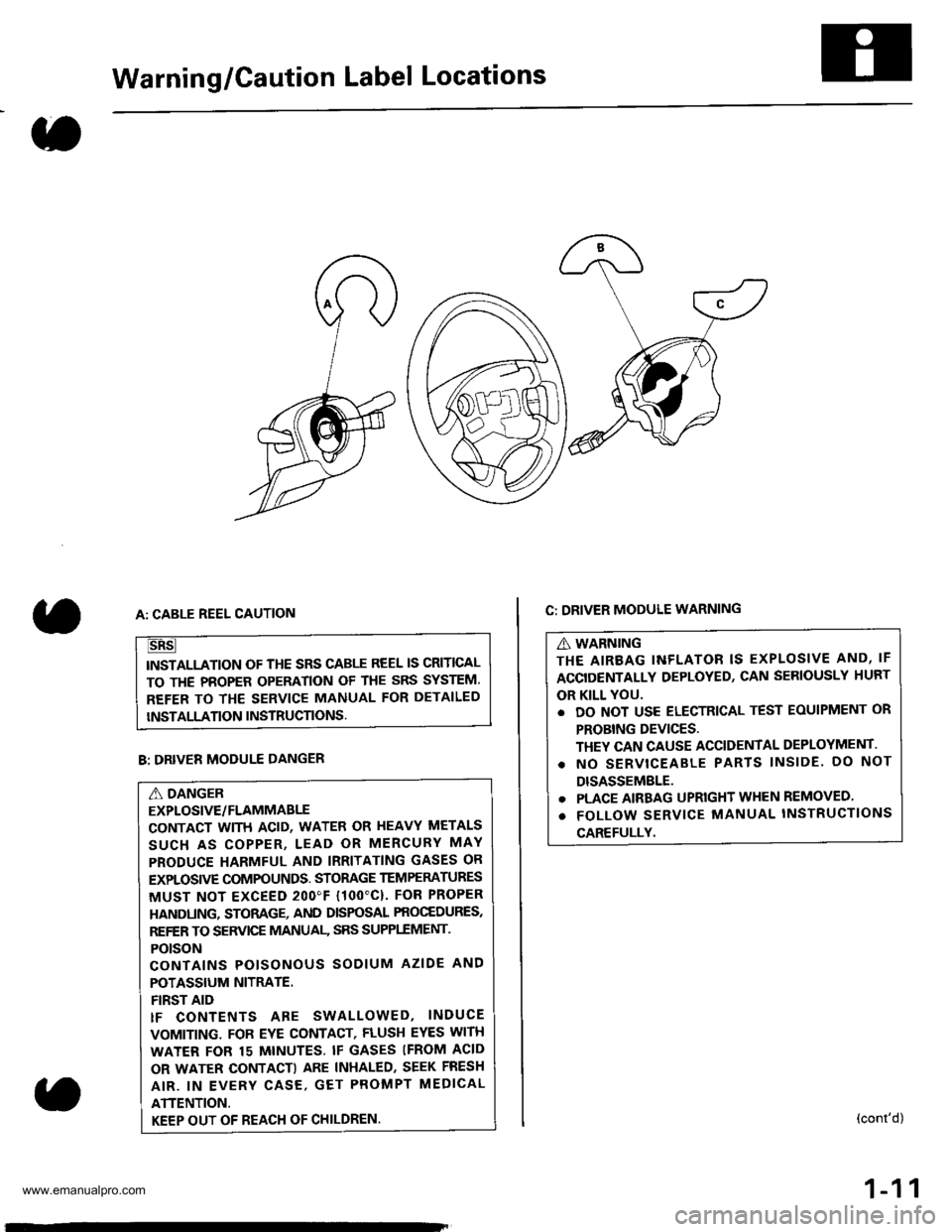
Warning/Caution Label Locations
C: DRIVER MODULE WARNING
A WARNING
THE AIREAG INFLATOR IS EXPLOSIVE AND, IF
ACCIDENTALLY DEPLOYED, CAN SERIOUSLY HURT
OR KILL YOU.
. DO NOT USE ELECTRICAL TEST EOUIPMENT OR
PROBING DEVICES.
THEY CAN CAUSE ACCIDENTAL DEPLOYMENT.
. NO SERVTCEABLE PARTS lNSlDE. DO NOT
DISASSEMBLE.
. PLACE AIRBAG UPRIGHT WHEN REMOVED
. FOLLOW SERVICE MANUAL INSTRUCTIONS
CAREFULLY.
A: CABLE REEL CAUTION
TNSTALLATION OF THE SRS CABLE REEL IS CRITICAL
TO THE PBOPER OPERATION OF THE SRS SYSTEM.
REFER TO THE SERVICE MANUAL FOR DETAILED
INSTALLATION INSTRUCTIONS.
(cont'd)
1-11
B: DRIVER MODULE DANGER
A DANGER
EXPLOSIVE/FLAMMABLE
CONTACT WITH ACID, WATER OR HEAVY METALS
SUCH AS COPPER, LEAD OR MERCURY MAY
PRODUCE HARMFUL AND IRRITATING GASES OR
EXPLOSIVE COMPOUNDS. STOMGE TEM PERATURES
MUST NOT EXCEED 2OO"F {1OO'C}. FOR PROPER
HANDUNG, STORAGE, AND DISPOSAL PROCEDURES.
REFER TO SERVICE MANUAI- SRS SUPPI.EMENT,
POTSON
CONTAINS POISONOUS SODIUM AZIDE AND
POTASSIUM NITRATE.
FIRST AID
tF CONTENTS ARE SWALLOWED, INDUCE
VOMITING. FOR EYE CONTACT, FLUSH EYES WITH
WATER FOR 15 MINUTES. IF GASES IFROM ACID
OR WATER CONTACTI ARE INHALED, SEEK FRESH
AIR. IN EVERY CASE, GET PROMPT MEDICAL
ATTENTION.
KEEP OUT OF REACH OF CHILDREN
www.emanualpro.com
Page 17 of 1395
![HONDA CR-V 1998 RD1-RD3 / 1.G Workshop Manual
Under-hood Emissions Control Label
Emission Group ldentification
(1997 modell
Example:
VACUUM HOSE ROUTING DIAGRAM
LOADED IM TEST]NG OF PERMANENT fOUB WHEEL OSVE OR TRACT ON CONTROLEOLJIPPEDVEHTCLES HONDA CR-V 1998 RD1-RD3 / 1.G Workshop Manual
Under-hood Emissions Control Label
Emission Group ldentification
(1997 modell
Example:
VACUUM HOSE ROUTING DIAGRAM
LOADED IM TEST]NG OF PERMANENT fOUB WHEEL OSVE OR TRACT ON CONTROLEOLJIPPEDVEHTCLES](/img/13/5778/w960_5778-16.png)
Under-hood Emissions Control Label
Emission Group ldentification
(1997 modell
Example:
VACUUM HOSE ROUTING DIAGRAM
LOADED IM TEST]NG OF PERMANENT fOUB WHEEL OSVE OR TRACT ON CONTROL'EOLJIPPEDVEHTCLES MUST BE CONDUCTED ON A IOUR WHEEL DR VE SPEEO SYNCHRON ZED
ANON LOADEDTESTPBO(EOUBEMUSIBEPERFORMEO
50ST (50 Statesl:
THIS VEHICLE CONFOBMS TO U.S. EPA AND STATE OF
CALIFORNIA REGULATIONS APPLICABLE TO 1997
MODEL YEAR NEW LIGHT DUTY TRUCKS.
49ST {49 Statos/Federall:
THIS VEHICLE CONFORMS TO U.S. EPA REGULATIONS
APPLICABLE TO 1997 IVIODEL YEAR NEW LIGHT DUTY
TRUCKS.
CAL (Calitornial:
THIS VEHICLE CONFORMS TO U.S. EPA AND STATE OF
CALIFORN IA REGULATIONS APPLICABLE TO '1997
MODEL YEAR NEW TLEV LIGHT DUTY TRUCKS
PROVIDED THAT THIS VEHICLE IS ONLY INTRODUCED
INTO COMMERCE FOR SALE IN THE STATE OF
CALIFORNIA.
Ii/PORTANT VEHICLE INFORIMATIONENGINE FAMILY VHN2 OIJCrcKDISPIACEMENT'2 OLITEREVAPORAT VE f AM]LY VNNl0778YMBP
CATALYSTREfERTOSEBVICEMANUALfORAODITIONAL NFORMATON.TUNT I-]P CONDITIONSENGINE AT NORI\,!AL OPERATNG TEMPERATURE,ALLACCESSOR ES TL]RNED OFF COOLING FAN OIFTRANSM1SSION NNEUTRALNO OTHEB ADJUSTMENIS NEEDED
ap' | \6( Zror '. ND \. 61F L r
TNIS VENICLE CONFORMS TO U.S EPA REGUI.ATIONSAPPI CASLE TO I99] MODET YEAR N€W L GNI DUTY TRACKS
@
Engine Family: vHN2.o l JGKE
Engine and Evaporative Families
T_fT
Model Year I Iv:1s97 | LManufaqturer iHN: Honda I
Displacement
Class
1: Light Duty Vehicle
Fuol Systom ,nd Numb€r of valves
J: Electronic Sequential Multiport
Injection (three or more valves per
cylinder)
Fuel Type
G: Gasoline
Standard
F: 49 or 50 States Tier 1
K: 49 or 50 States Tier 1
1: California Tier 1
2: California TLEV
3: California LEV
4: California ULEV
"r0", "*,
T|
V: 1997
Manufacturer
HN: Honda
Catalyst
E, F, G, H: Three Way Catalyst
OBD
K - T: OBD Equipped
Evaporative Family:
Storago System
1: Canister
Canistor Working Capacity (gramsl
Canister Conf igulation
A: Plastic Housing (Closed Bottom)
B: Plastic Housing (OPen Bottom)
Fusl System
Y: Fuel Injection
FuelTank
M: Metal
Standard
A: Current Evap
B: Enhanced Evap
Wild C.rd
VHNlOTTBYMBP
1-1 5
www.emanualpro.com
Page 18 of 1395
Under-hood Emissions Control Label
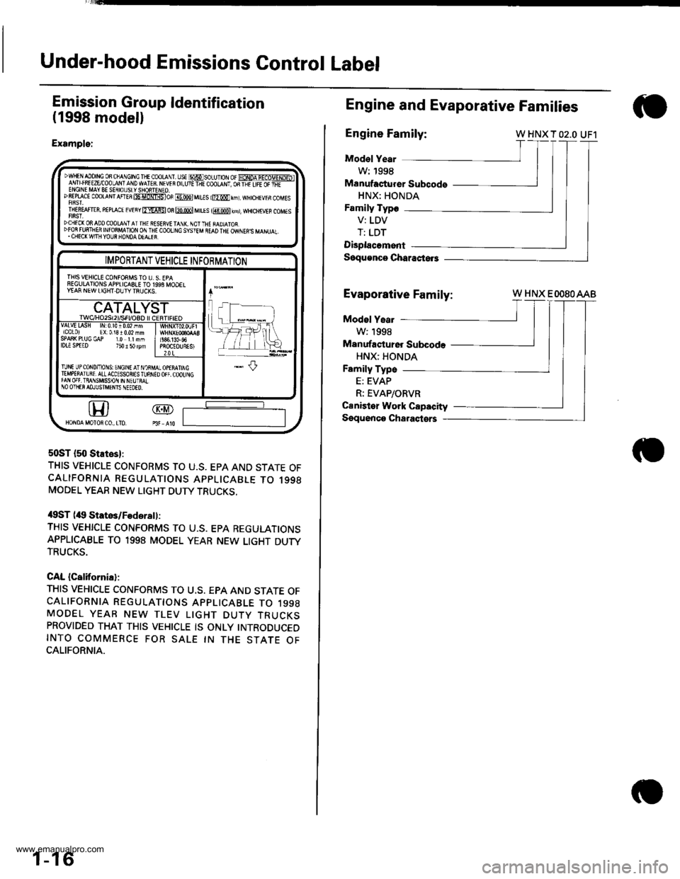
Emission Group ldentification
(1998 modell
Example:
50ST {50 States}:
THIS VEHICLE CONFORMS TO U.S. EPA AND STATE OFCALIFORNIA REGULATIONS APPLICABLE TO 1998MODEL YEAR NEW LIGHT DUTY TRUCKS,
/$ST (itg Statos/Fodsrsll:
THIS VEHICLE CONFORMS TO U.S. EPA REGULATIONSAPPLICABLE TO 1998 MODEL YEAR NEW LIGHT DUTYTRUCKS.
CAL {California}:
THIS VEHICLE CONFORMS TO U.S. EPA AND STATE OFCALIFORNIA REGULATTONS APPLICABLE TO 1998MODEL YEAR NEW TLEV LIGHT DUTY TRUCKSPROVIDED THAT THIS VEHICLE IS ONLY INTRODUCEDINTO COMMERCE FOR SALE IN THE STATE OFCALIFORNIA.
DwlF AIo|NG oB cha\Gtftc I + coot r
-s€ msoru1or or FoNoA-IEaoTTxD-ibl1'v! Lrff EzEcoo-aN' a\D wATfB. M w r or_ut-ir coolqNt, oR-l;ir,FEaFEf-ENGINE MAY BE SEflIOUSLYSIONTENEO.DSEPLACI CoOTANT AnEs 85 itNlgsloF @ MILIS l@0 rnl, wHrcHEvEs coMEs
TNEREAFT€R, REPLACE EvEny fmAFSl m m M[Es i@ kml, wHcHrvEB coMEs
DCHEC(ONADOCOOLqNTATTHE RSSEFVETANX. NOTTHE iAD]ATOR.DFOR FUFTNEfr INFO8MATION ON IN€ COOT]NC SYSIEM NEAD THE OWNEN'S MANUAL,. CHECK W|TH YOUR NONDA OEALEF.
@GD
IMPORTANT VEHICLE INFORMATION
THIS VEHICLE CONFOEMS TO I], S. EPAFEGIJLAIIONSAPPLICASLE TO 1993 MOOELY€AF NEW LIGHT DUIYTNUCXS.
CATALYSTrwqHozst2l/sFt/osD l cERI|FtEOvAlvttAsH lrr0.l010.02nmicolo) EX:01310.02mmSPAS( PIUG GAP I.O IINMlDLl SPTED 750 I 50 rym686,13G96PROCEOURESI2.0 L
TlNt UPCoND/ToNS: ENGINE AT NOiMIEMPETAIURT,ALLACCESSORIESTUNNIfAN OFf. TRAI1SMISSON IN NEUTMINO OIIIER AOJUSTI\TFIIS IIEEOED.
1-16
Engine and Evaporative Families
Engine Family:W HNX T O2.O UF1
Mod€l Year
W: 1998
Manufacturer Subcods
HNX: HONDA
Family Typo
V: LDV
T: LDT
Displacomsnt
Soqu€nco Characiors
Evaporative Fami
Family:
Model Yeat
W:1998
Manufastu16r Subcode
HNX: HONDA
Family Type
E: EVAP
R; EVAP/ORVR
Canister Work Capacity
Sgquonco Charaqtsrs
W HNX EOOSOAAB
www.emanualpro.com
Page 19 of 1395
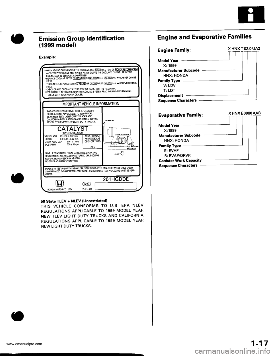
Emission Group ldentification
(1999 model)
Example:
50 state TLEV + NLEV {Unrestricted}
THIS VEHICLE CONFORMS TO U.S. EPA NLEV
REGULATIONS APPLICABLE TO 1999 MODEL YEAR
NEW TLEV LIGHT DUTY TRUCKS ANO CALIFORNIA
REGULATIONS APPLICABLE TO 1999 MODEL YEAR
NEW LIGHT DUTY TRUCKS.
'.WNEN AOO NG OR CNANGINC THE COOLANT. USE @SOLU I ON Of FONOA U-ECo-q.�NOEDImcrtniuvcoourr mo wlttt NEVEF oILLJTE THE CooLANT,0RTHE LIFE 0F TNE
"Eifil:$o""niii?i,THffi ffi'"R @ M LEs lmo rhl, wNrcHEVEn coMEs
i'lrt^t orrrr, ^,r*a, rurr"* os @ M LEs 1@ kmr wNICHEVER coMEs
}CNECK OR ADD COOLANT AT THE RESER!'E TAN( NOT IHE NADIATOSDFOfi fWTHEF NFORMATION ON THE COOL NC SYSTEM READ THE OWNER'S MANUAL'' CHECK WIIH YOUS HONOA OEALER.
GD
IMPORTANT VEHICLE INFORMATION
THIS VEHICLE CONFOAMSTOU. S EPA NLEVFEGULANONS APPLICCBLI TO 1999 MOD€LYEA8 NEW TIEV LIGHT DUTY ]nUCKS ANDCALIFORNIA REGULATIONS APPLICASLE IO 19S9MOOEL YEAR NEW TLEV LIGHT DUTY IFIJCKS,,|F --'-
Ll: .-.-,1
I rFrll\=#_H*
CATALYST
VALVE IASN lN:010r0.02 mmlCoLDj EX 0131002 mmSPA8K PLUG GAP 10- l l nmIDLE SPEED 130 t 5{ rPmOBDIICERT]ATD
201
TUNE I]PCONDIIIONS INGINEAT NOBTEI\'PERATUR€ ATL ACCESSOS ES TLJRNFAN OFf IRANSMSSION N NEL]TMLNO OINER ADJUSTMTNTS NEEOEO.
JL
Iooro nr tist rc orn svtncrE MUsT BE coMoufitooNArounwNEElDslvE SPEEDiitriunor mo ovuvo uenn orr Enw sE a NoN.loaDE D rEsr PRoCE ouRE MU sT 8E Pf Rr-
Engine and Evaporative Families
Engine Family:X HNX T02,O UA2
Model Year
X:1999
Manutao{urer Subcode
HNX: HONDA
Family Type
V: LDV
T: LDT
Displacoment
Saquence Charactors
Evaporative Family:X HNX EOO8OAAB
Model Yoal
X:1999
Manutacturar Subcode
HNX: HONDA
Family Typo
E: EVAP
R: EVAP/ORVR
Canbter Work Capacity
S€quonce Chartsters
1-17
www.emanualpro.com
Page 20 of 1395
Under-hood Emissions Control Label
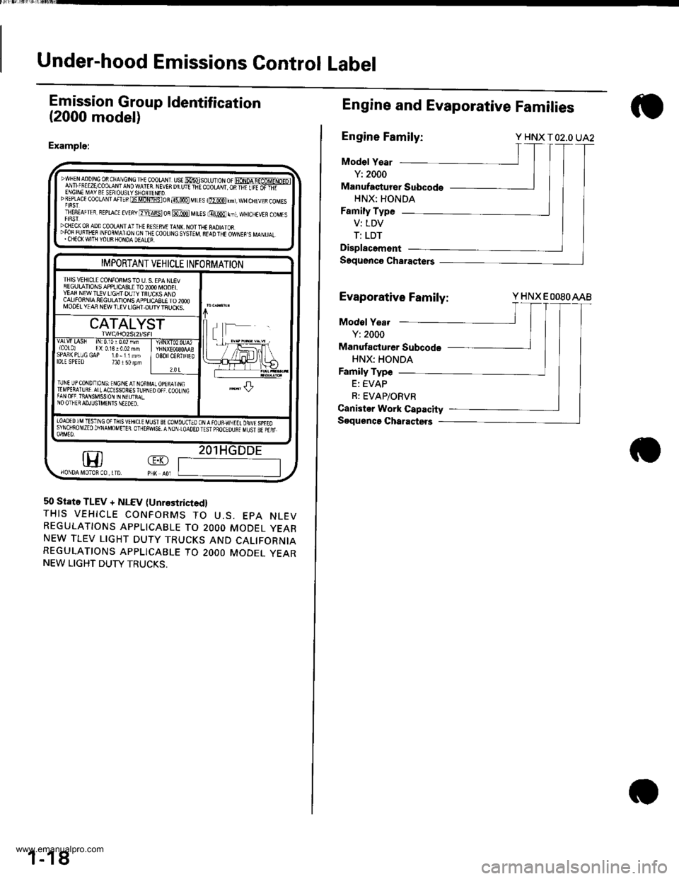
Emission Group ldentification
(2000 model)
Example:
DWFEN aDD r,tc 0R ChA\CtN! rlt cooraN. ust MsoLU- oN or fioNpA q-af6MrNp-ol
lfi ;!,."5:P!$t:1t9ffilf 1
vEn u u'r +-E coo|-d',r os-Fiiiiifi-'DREpf cE coolaNrAFTEBt3tlomistoR@MtLEs r@km),wH ctlEvrscoMEsT|E8EAFTER, BEprAcE EVEny ErdFst oB @ MttEs lmr,t, ffitcHEVER coMEsDCIIICX OF ADD COOLA I I'-FE AISIRVI TAI{I\. NOI THE MDIAIOR":3lliJ#fl "lj,9lx6L;T&Iji(0or|]\G s,5TEM 8r!D TrE owrEp s MA\u.r.
m
IMPORTANT VEHICLE INFORMATION
IHIS \/IHICLE CONFONMS TO U. S. EPA NLEVSEGULATIONS APPIJCq3LE TO 2OOO IVOOELYEAF NEW T!!V LIGHT DUTY TBUCKS ANDCALIFONNIA SEGULATIONS APPLICASLE TO 2OOOMOO€L YIAA NEW TLEV LIGHT.OUTY TFIJCKS.
CATALYST
vALvt LA5h tN:0,10r0.02 mm{C0t0l El:0.13!002 mhSPAn(PLUGGAP 1.0-11mmlDlE SPEEo 734150lpmO8O CENTFIED
?.0 t
TUNI UP CoNDIToNS: ENGINE AT NORMTTMPERAIURE ATLACCESSORIES fu BNITAN OFF TiANSMISS ON IN N€UTRALNO OTHER AD.ILJSTMENIS NEEDEO.
.l-L
|oAoEDr/MTESTNG oFTHsvtHrctE uLrst gt couolorooN,{raua.wxEtt onuspreosyNoiRoN zEo DvNAMoMETER. olrEiwsE. A NoN.LoAoEo rEsr pBocEounr uust sr pair
1
50 State TLEV + NLEV (Unrestricied,
THIS VEHICLE CONFORMS TO U.S. EPA NLEVREGULATIONS APPLICABLE TO 2OOO MODEL YEARNEW TLEV LIGHT DUTY TRUCKS AND CALIFORNIAREGULATIONS APPLICABLE TO 2OOO MODEL YEARNEW LIGHT DUTY TRUCKS.
1-18
Engine and Evaporative Families
Engine Family:Y HNX TO2.O UA2
Model Y€ar
Y: 2000
Manufaqturer Subcodo
HNX: HONDA
Family Type
V: LDV
T: LDT
Displacement
Saquenco Charasters
Evaporative Family:Y HNX EOOSOAAB
Modol Yea.
Y: 2000
Manufacturer Subcode
HNX: HONDA
Family Type
E: EVAP
R: EVAP/ORVR
Canister Work Capacity
Soquenca Charactet3
www.emanualpro.com
Page 23 of 1395
Towing
lf the vehicle needs to be towed, call a professional
towing service. Never tow the vehicle behind another
vehjcle with just a rope or chain. lt is very dangerous.
Emergency Towing
There are three popular methods of towing a vehicle.
Flat-bed Equipment - The operator loads the vehicle on
the back of a truck. This is the best way of transporting the
vehicle.
Wheel Lift Equipment - The tow truck uses tlvo pivoting
arms that go under the tires lfront or rear) and lifts them
off the ground. The other two tires remain on the
ground. The vehicle's suspension and body can be
seriously damaged if this method of towing is attempted.
Sling-type Equipment - The tow truck uses metal cables
with hooks on the ends. These hooks go around parts of
the frame or suspension and the cables lift that end of
the vehicle off the ground. The vehicle's suspension and
body can be seriously damaged if thjs method of towing
is attempted. This methed of towing the CR-V is
unaccePtable.
The onlv recommended way of towing the CR-V is on a
flat-bed truck. Two wheel drive CR-V's may also be
towed with all four wheels on the ground.
Towing the four-wheel dlive CR-v with only two
wheels on the ground will damage parts of the 4wD
system. It this vehicle is damaged, it should be towed
on a flat-bed truck ol trailel.
It the 2 wheel drive CR-v is towed wiih all tour wheels
on the ground, do the following:
Manual Transmission
. Release the parking brake.
. Shift the transmission in Neutral
Automatic Transmission
. Release the parking brake.
. Sta rt the engine.
. Shift to lD.l position. then E position.
. Turn off the engine.
lmproper towing preparation will damage the
transmission. Follow the above procedure exactly. lf
you cannot shift the transmission or start the engine,
the vehicle must be transported on a flat-bed truck.
lf the vchicle is towed with four wheels on the ground,
il is best to tow the vehicle no larther than 50 miles (80
km), and keep the speed below 35 mph {55 km/h).
Trying to lift or tow the vehicle by ihe bumpers will
cause serious damage. The bumpers ale not dosigned
to support the vehicle's weight.
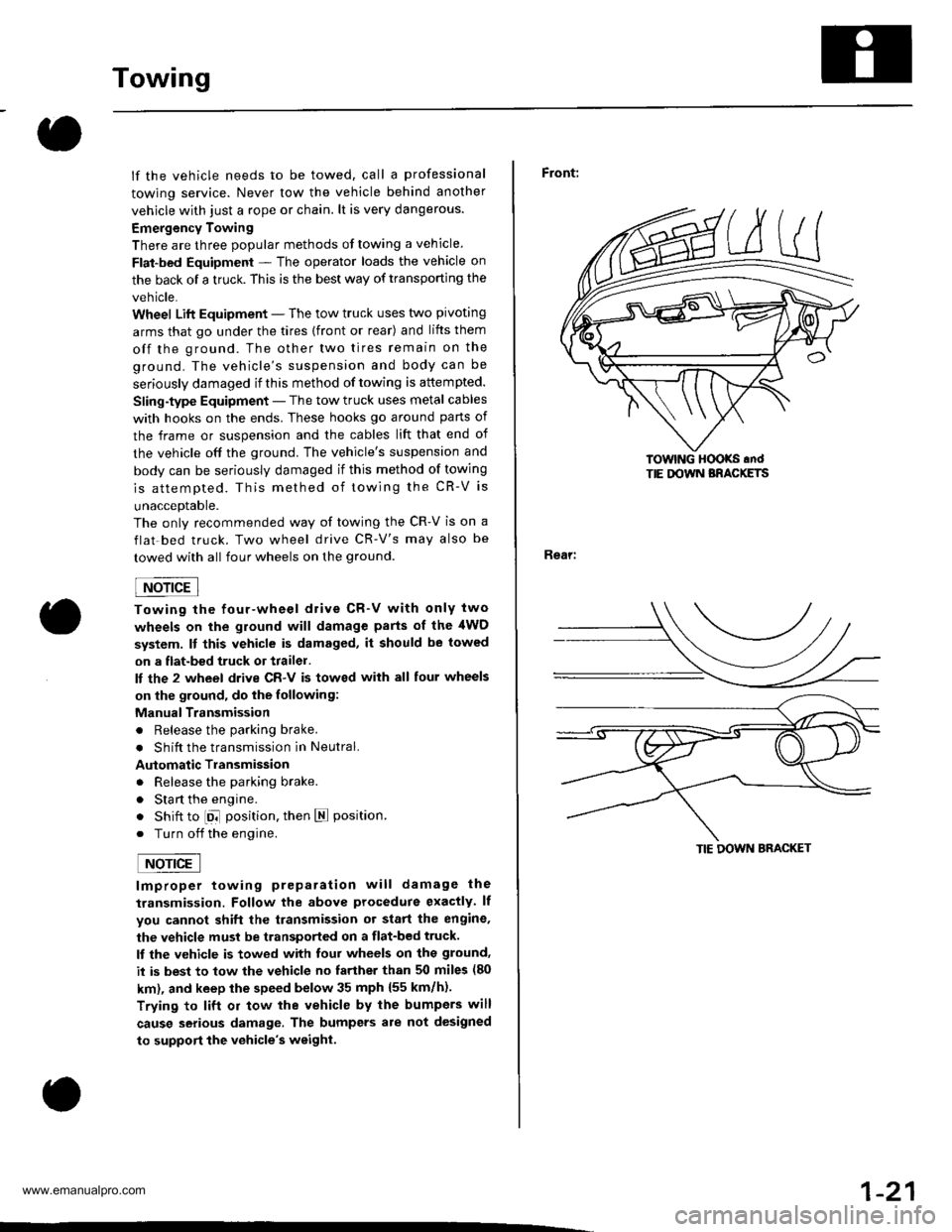
Front:
Rear:
lOwlNG HOOKS .ndTIE DOWN BRACKETS
TIE DOWN BRACKET
1-21
www.emanualpro.com
Page 41 of 1395

Lubrication Points
For the details of lubrication points and type of lubricants to be applied. refer to the illustrated index and various work pro-
cedures (such as Assembly/Reassembly, Replacement, Overhaul, Installation, etc.) contained in each section.
Recomm6nded Engine OilEngine oil viscosity for ambient temperature ranges
100'F
-30 -20 .10 0 10 20 30 40'c
r1: Always use Genuine Honda Manual Transmission Fluid {MTF). Using motor oil can cause stiffer shifting because it
does not contain the orooer additives.*2: Always use Genuine Honda Premium Formula Automatic Transmission Fluid (ATF). Using a non-Honda ATF can affect
shift qualitv.+3r Always use Genuine Honda DOT 3 Brake Fluid. Using a non-Honda brake fluid can cause corrosion and decrease the
life of the system.*4: Always use Genuine Honda Power Steering Fluid. Using any other type of power steering fluid or automatic transmis-
sion fluid can caused increased wear and poor steering in cold weather.
API SERVICE LABEL
/,.*-G\
/.'z-\e\t/6AE\ll-;-1 5w-30 /---l
w
API CERTIFICATION SEAL
ffi-20 0 20
NO.LUBRICATION POINTSLUBRICANT
EngineAPI Service Grade: Use SJ "Energy Conserving" grade oil. The oilcontainer may also display the API Certitication seal shownbelow. Make sure it says "For Gasoline Engines." SAE vjscosity:See chart below.
2
TransmissionManualGenuine Honda MTF*1
AutomaticGenuine Honda Premium Formula Automatic Transmission Fluid(ATF)*'
3Rear differentialGenuine Honda CVT Fluid
4Brake line (includes ABS line)Genuine Honda DOT 3 Brake Fluid*3
5Clutch LineBrake fluid DOT 3 or DOT 4*3
6Shift lever pivots (Manual transmission)Grease with molybdenum disultide
1Release fork (Manual transmission)LJrea Grease UM264 P/N 4'1211 - PYs - 305
IPower steering gearboxSteering grease P/N 08733 - B070E
Throttle cable end {Dashboard lower panel holelSilicone grease
10l112
14
Throttle cable end (Throttle link)Brake master cylinder pushrodPedal linkageBattery terminalsFuelfill lidClutch master cylinder pushrod
Multi purpose grease
1617181920
Hood hinges and hood lockTailgate hingesHatch glass hingesDoor hinges, upper and lowerDoor opening detent
Honda White Lithium Grease
21
22
Caliper Piston seal, Dust seal,Caliper pin, PistonShilt cable and select cable {Manual transmission)Silicone grease
23Brake line ioints (Front and rear wheelhouse)Rust preventives
24Power steering systemGenuine Honda Power Steering Fluid-.
25Air conditioning compressorCompressor oil: SP 10 lP/N 38897 - P13 - A0lAH or38899-P13-A01)For Refrigerant: HFC 134a (R,134a)
3-2
www.emanualpro.com
Page 51 of 1395
Engine Electrical
Speciaf Tools ............. 4-2
Starting System
Component Location Index ............ 4-3
Circuit Diagram ................................ 4-4
Starter Test ........... 4-5
Starter Solenoid Test ...................... 4'5
Starter Replacement ....................... 4-7
Field Winding Test ........................... 4-7
Starter Overhaul ............................,. 4-8
Brush Inspection ...........................,., 4-9
Overrunning Glutch Inspection ...... 4-9
Armature lnspection and Test ........4-10
Brush Holder Test ............................ 4-12
Starter Reassemb|y ......................... 4-1 2
Perf ormance Test ............................. 4- 1 3
lgnition System
Component Location Index ............ 4-14
Circuit Diagram ................................ 4-15
lgnition Timing Inspection and
Setting .......................................... 4-16
Distributor Replacement ........,........ 4-17
Distributor Overhaul .............,,......... 4-18
lgnition Control Module (lCM) Input
Test ..............................,................ 4-19
fgnition Coil Test .............................. 4-2O
lgnition Wire Inspection and
Test ............................................... 4-20
Spark Plug Inspection ..................... 4-21
-+
ENGINE
Charging System
Component Location Index ............ 4-22
Circuit Diagram ....................,........... 4-23
Troubleshooting .............................. 4-24
Alternator Replacement ..........,....... 4-30
Alternator Overhaul .......,,................ 4-31
Rectifier Test .........4-32
Alternator Brush Inspection ........... 4-32
Rotor Slip Ring Test ........................ 4-33
Stator Test ............. 4-33
Alternator Belt Inspection and
Adiustment ........4-34
Gruise Control
Component Location Index .,,,........ 4-36
Circuit Diagram ................................ 4-37
Control Unit Input Test ................... 4-38
Main Switch Test/Replacement ..... 4-40
Set/Resume Switch Test/
Replacement .......................,........ 4'40
Actuator Test ....,,., 4-41
Actuator Replacement ...............,.... 4-42
Actuator Cable Adiustment ............ 4-43
Clutch Switch Test .......................... 4-43
Brake Switch Test .................. .......... 4-44
Actuator Solenoid Test .............. ...,. 4-44
Actuator Disassembly ..................... 4-45
www.emanualpro.com
Page 55 of 1395

Starting System
Starter Test
NOTE: The air temperature must be between 59 and'100'F (15 and 38"C) before testing.
Recommended Procedure:
. Use a staner system tester.
. Connect and operate the equipment in accordance
with the manufacturer's instructions.
. Test and troubleshoot as described.
Alte.nate Procedure:
. Use the following equipment:- Ammeter, 0 - 400 A- Voltmeter, 0 - 20 V (accurate within 0.1 volt)
Tachometer,0 - 1,200 rpm
. Hook up a voltmeter and ammeter as shown.
NOTE: After this test, or any subsequent repair. reset
the ECM/PCM to clear any codes (see section 1 1).
Check the Starter Engagement:
'1. Remove the No. 44 (15 A) fuse from the under-hood
fuse/relay box.
2. Turn the ignition switch to START (lll) with the shift
lever in E or E position (A/T) or with the clutch
pedal depressed {M/T). The starter should crank the
eng ine.
. lf the starter does not crank the engine, go to
step 3.
. lf it cranks the engine erratically or too slowly, go
to "Check for Wear and Damage" on the next
page.
NEGATIVE TERMINAL
4.
5.
6.
7.
8.
Check the battery, battery positive cable, ground.
staner cut relay, and the wire connections for loose-
ness and corrosion. Test again.
lf the staner still does not crank the engine, go to
step 4.
Unplug the connector (BLK /VHT wire and solenoid
terminal) from the starter.
Connect a jumper wire from the baftery positive (+)
terminal to the solenoid terminal.
The starter should crank the engine.
. lf the starter still does not crank the engine,
remove it, and diagnose its internal problem.
. lf the starter cranks the engine, go to step 6.
Check the ignition switch (see section 23).
Check the starter cut relay {see section 23}.
Check the IVT gear position switch (A/T) or the clutch
interlock switch (M[).
Check for an open in the wire between the ignition
switch and starter.
(cont'd)
4-5
www.emanualpro.com
Page 57 of 1395
RE
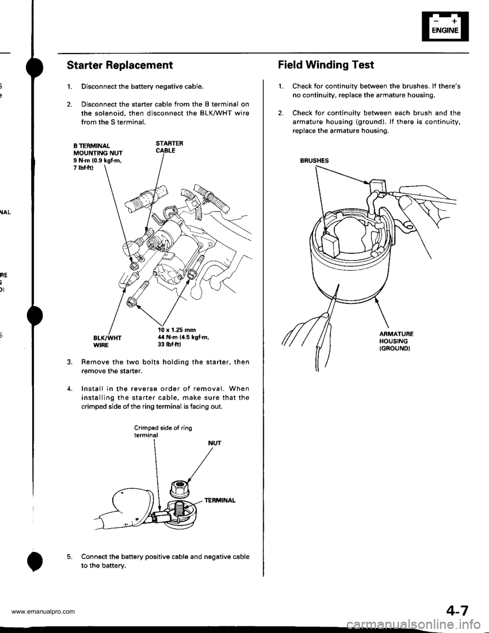
Starter Replacement
1.
B TERMINALMOUNNNG NUTI N.m (0.9 kgl.m,7 rbt ftl
Remove the two bolts holding the starter. then
remove the starter.
4. Install in the reverse order of removal. When
installing the starter cable, make sure that the
crimped side ofthe ring terminal is facing out,
Crimped side of ringterminal
TERMINAL
Connect the battery positive cable and negative cable
to the batterv.
Disconnect the battery negative cable.
Disconnect the starter cable from the B terminal on
the solenoid. then disconnect the BLK/WHT wire
from the S terminal.
STARTER
l0 x 1.25 mm4,1 N.m {4.5 kgf.m,33 tbt.ftl
5.
o
Field Winding Test
Check for continuity between the brushes. lf there's
no continuity, replace the armature housing,
Check for continuity between each brush and the
armature housing {ground). lf there is continuity.
replace the armature housing.
t.
ERUSHES
4-7
www.emanualpro.com