Ac belt HONDA CR-V 1998 RD1-RD3 / 1.G Workshop Manual
[x] Cancel search | Manufacturer: HONDA, Model Year: 1998, Model line: CR-V, Model: HONDA CR-V 1998 RD1-RD3 / 1.GPages: 1395, PDF Size: 35.62 MB
Page 1372 of 1395
)
Ftom page 2!-7 a
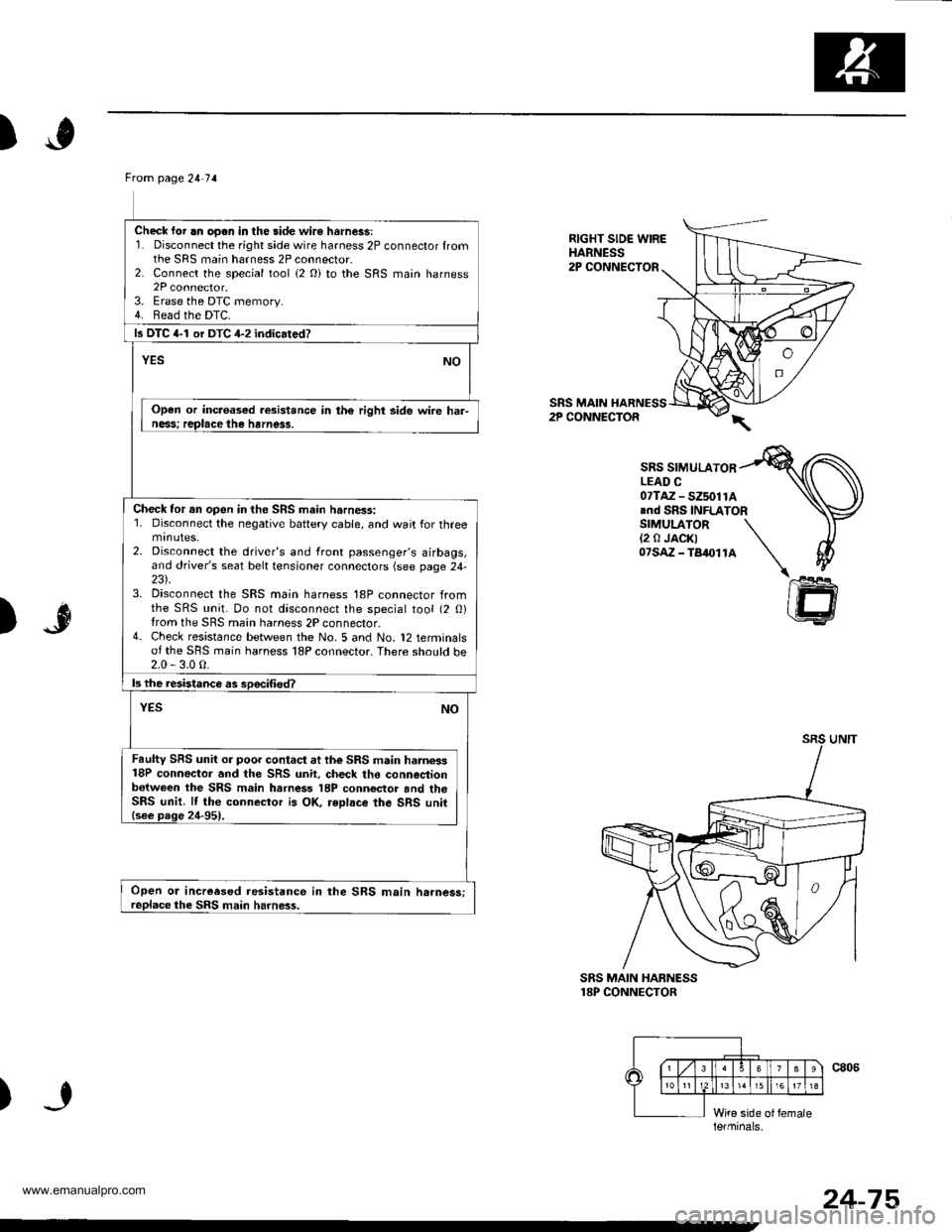
Check lor .n oo.n in the side wire hsrness:1. Disconnect the right side wire harness 2P connector fromthe SRS main harness 2P connector.2. Connect the special tool (2 Oi to the SRS main harness2P connector.3. Erase the DTC memory.4. Bead the DTC.
ls DTC 4-1 or DTC 4-2 indicated?
NOYES
Open or inc.oased resistance in th€ right side wire har-ness; replace the harness.
Check tor an open in the SRS main harness:1. Disconnect the negative battery cable, and wait for threemtnutes.2. Disconnect the driver's and front passenger's airbags,and driver's seat belt tensioner connectors (see page 24-23\.3. Disconnect the SRS main harness 18P connector fromthe SRS unit. Do not disconnect the special tool (2 0)from the SRS main harness 2P connector.4- Check resistance between the No. 5 and No. 12 terminalsof the SRS main harness 18P connector. There sho!ld be2.0 - 3.0 0.
ls the resistanca as soecified?
NOYES
Faulty SRS unit or poor contact at the SRS main harne3s18P conneclor and the SRS unit, check the connestionb€tween the SRS main harness 18P conn€ctor and th6SRS unit. lf the connector is OK, reDlace the SRS unit{see page 24-951.
Open or increesed resistanco in the SRS main h.rnes3;replace the SRS main harness.
RIGHT SIDE WIREHARNESS2P CONNECTOR
SRS MAIN HARNESS2P CONNECTOR
SRS SIMULATORLEAD C07TAZ - SZ5011A.nd SRS INFLATORSIMULATOR(2 0 JACK)07sAz - TB4011A
)"r$
SRS MAIN HABNESS18P CONNECTOR
)
le.minals.
24-75
www.emanualpro.com
Page 1373 of 1395
Troubleshooting
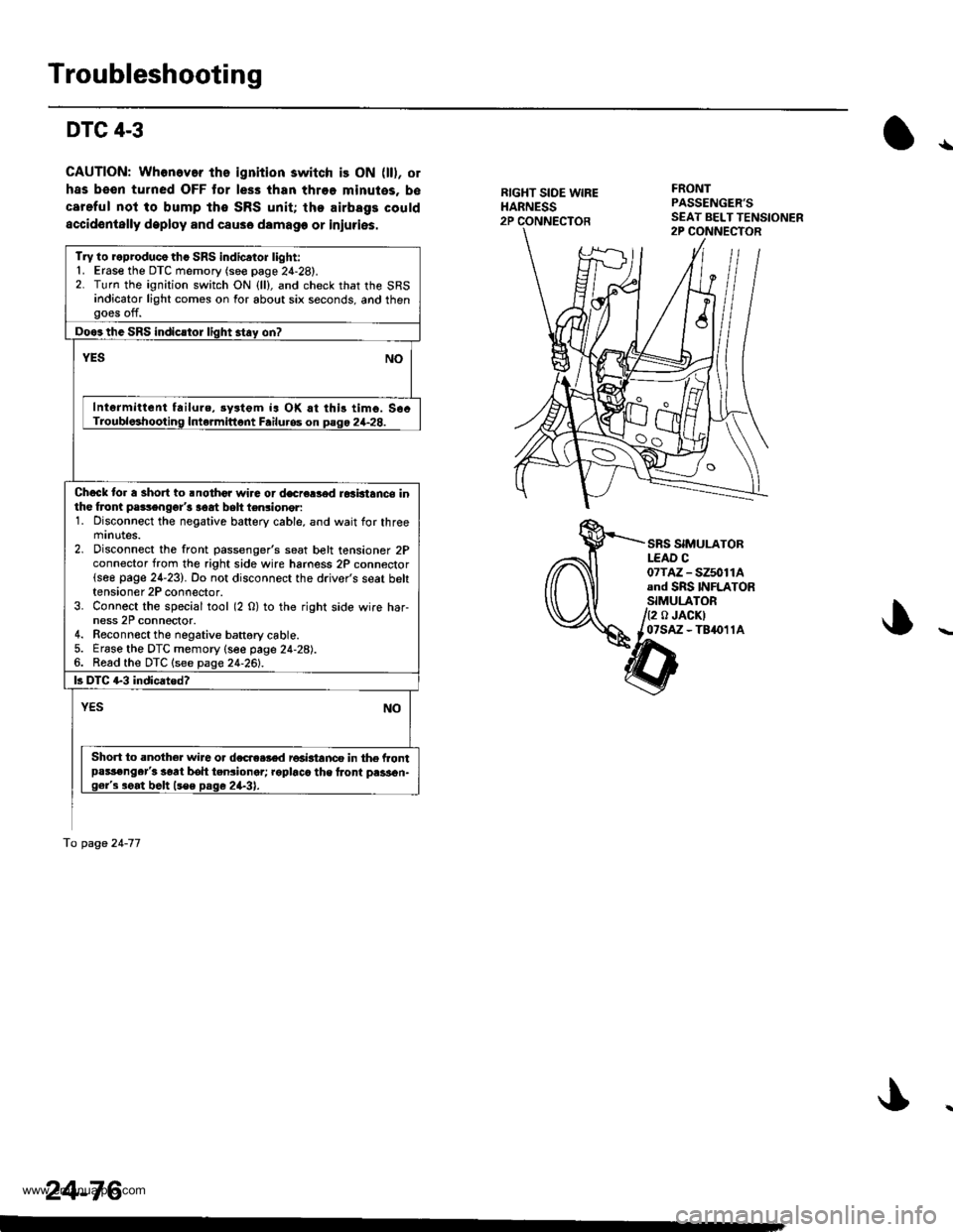
DTC 4-3
CAUTION: Whonev.r ths ignition switch is ON (ll), or
has been turned OFF tor less than throe minutes, b€
careful not to bump tho SRS unit; the airbags could
accidentally deploy and csuse damage or iniuries.
{
RIGHT SIDE WIREHARNESS2P CONNECTOR
FRONTPASSENGER'S
SRS SIMULATORLEAD C07TM - SZ5011Aand SRS INFLATORSIMULATOR
/2 o JACKIl07sAz - TB4011A
tnat2s>,-ar'--\>
Try lo reproducothc SRS indicator light:'1. Erase the DTC memory (see page 2{-28).2. Turn the ignition switch ON {ll}, and check that the SRSindicator light comes on for about six seconds, and thengoes off.
Doos the SRS indicstor light stay on?
YESNO
Intermittent failure, rystgm ia OK rt this timo. S6cTroubloshooting Intermittont Failu.os on pago 2+28.
Chock to. a short to .nothor wira or decre8od ro3btance inthe froni pa3sengor'3 aoat belt ten3ioner:1. Disconnect the negative battery cable, and wait for threemrnutes.2. Disconnect the front passenger's seat belt tensioner 2Pconnector from the right side wire hamess 2P connector(see page 24-23). Do not disconnect the driver's seat belttensioner 2P connector.3. Connect the special tool (2 O) to the right side wire har-ness 2P connoctor.4. Reconnect the negative battgry cable.5. Erase the DTC memory (see page 24-28).6. Read the DTC lsee page 24-261.
|3 DTC G3 indicatod?
YESNO
Short to .noth6r wire o. dc6e.r€d r€aktanco in the frontpassenger'3 s€at boh teniioner; roplacc the lront pass6n-g6r's aeat belt (s€e psge 2a-31.
To page 24-77
24-76
www.emanualpro.com
Page 1374 of 1395
From page 24-76
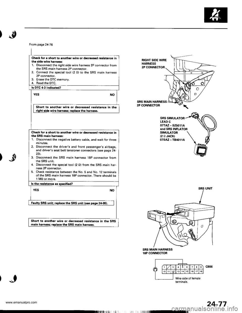
Chock to. a aho.l to lnothcr wire or d€creslod rosbtanco inth. side wiro harn.$:1. Disconnoct the right side wire harness 2P connector lromthe SRS main harness 2P connector.2. Connoct the special tool (2 O) to the SRS main harness2P connector.3. Erase the DTC memory.4. Read tho DTC.
13 DIC +3 indicated?
YESNO
Short to .noth6r wiro or doc.oasod r.sistanco in thGdght sida wiro ha]ne3s; rapl.ce the hamcas.
Chack loi a short to anothor wire o. docreas€d rGbtancc intho SRS main h.]n€$:1. Disconnect the negative battery cable, and wait for threemtnutes,2. Disconnect th6 driver's and front passenger's airbags,and driver's seat belt tensioner connectors (see page 24-
3. Disconnect the SRS main harness 18P connector fromthe SRS unit.4. Disconnect the special tool (2 0) from the SRS main har-ness 2P conn€ctor.5. Check resistance between the No. 5 and No. '12 terminalsof the SRS main harness 18P connector. There should be1 MO or more.
b the raaistanco aa soscifiedT
YESNO
F.ulty SRS unit; roplac€ tho SRS unit lseo pase 24-951.
Short to enothor wi.o or decree3od r*istance in the SRSmain harnoit rophco the SRS main ha.nsss.
RIGHT SIOE WIREHARNESS2P CONNECTOR
SRS MAIN2P CONNECTOR
SRS SIMULATORLEAD C07TAZ - SZ50114and SRS INFLATORSIMULATOR{2 0 JACK)07saz - Ta1ol1A
)
SBS MAIN HARNESS18P CONNECTOR
c806\6
15
l;iid€ of {6maleterminals,
I
24-77
www.emanualpro.com
Page 1375 of 1395
Troubleshooting
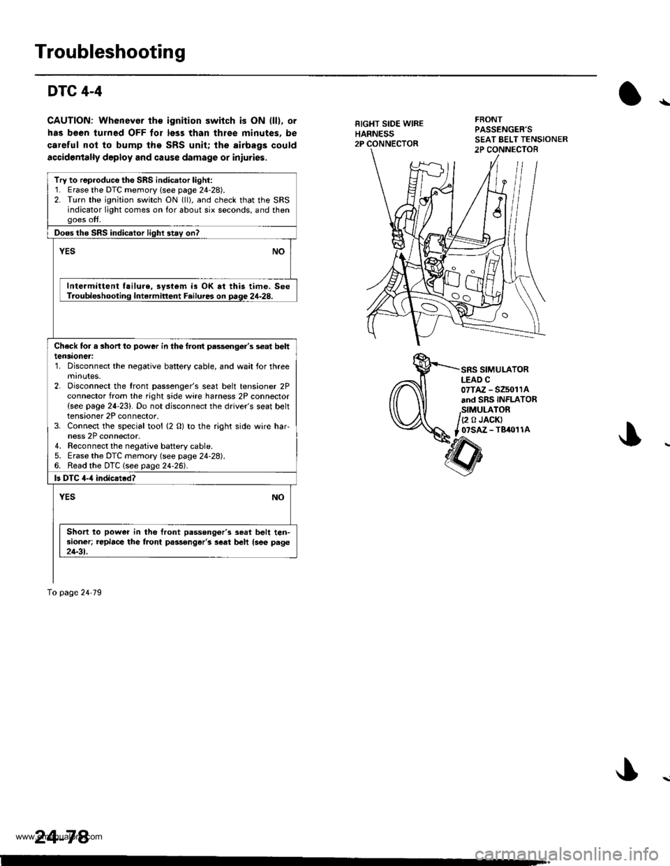
DTC 4-4
CAUTION: Whenever the ignition switch is ON (ll), or
has been turned OFF tor less than thlee minutes. be
careful nol to bump the SRS unit; the airbags could
accidontally deploy and cause damage or iniuries.
RIGHT SIDE WIREHARNESS2P
FRONTPASSENGER'S
SRS SIMULATORLEAD C07TAZ - SZ5011Aand SRS INFLATOR
,StMULATOR/(2 o JACK)
t _07SAZ - TBiro1 1A
Try to reproduce the SRS indicator light:1. Erase the DTC memory {see page 24-28).2. Turn the ignition switch ON (ll), and check that the SRSindicator light comes on for about six seconds, and thengoes off.
Doos the SRS indicator light 3t.y on?
vEsNO
Intermittent f!ilure, system is OK at this time. SeeT.oubleshooting Intermittent F.ilures on page 24-28.
Check tor a 3horl lo power in the frolt pass€nge.'s s€at belttensaoneri'1. Disconnect the negative battery cable, and wait for threemrnutes.2. Disconnect the front passenger's seat belt tensioner 2Pconnector from the right side wire harness 2P connector{see page 24-23}. Do not disconnect the driver's seat belttensioner 2P connector.3. Connect the special tool (2 O) to the right side wire har-ness 2P connector.4. Reconnect the negaiive baftery cable.5. Erase the DTC memory (see page 24-28).6. Read the DTC lsee page24-261.
ls DTC 4-,1 indicated?
YESNO
Short to power in the front passong6r'3 seat belt ten-sioner; replace the front passongar'3 s€at beh {see page21-31.
To page 24'79
24-78.
www.emanualpro.com
Page 1376 of 1395
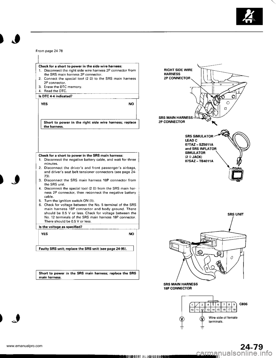
)
RIGHT SIDE WIREHARNESS2P CONNECTOR
SRS MAIN2P CONNECTOR
SBS SIMULATORLEAD C07TAZ - SZ5011Aand SRS INFLATORSIMULATOR \(2 0 JACK) \07sAz-T84011A \\
)J
)
@
SRS MAIN HARNESS18P CONNECTOR
Ftom page 24 78
Check for a short to power in the side wire harn6s:1. Disconnect the right side wire harness 2P connector fromthe SRS main harness 2P connector,2- Connect the special tool (2 0) to the SRS main harness2P connector.3. Erase the DTC memory.4. Read the DTC.
ls DTC 4-{ indicated?
YESNO
Short to power in the right side wire harness; replacethe harness.
Check tor a short to oow6r in the SRS main harness:1. Disconnect the negative battery cable, and wait for threemtnutes,2. Disconnect the driver's and front passenger's airbags,and driver's seat belt tensioner connectors (see page 24-23).3. Disconnect the SRS main harness 18P connector fromthe sRS unit.4. Disconnect the special tool i2 0) from the SRS main harness 2P connector, then reconnect the negative batterycaore.5. Turn the ignition switch ON (ll).
6. Check for voltage between the No. 5 terminal of the SRSmain harness 18P connector and body ground. Thereshould be 0.5 V or less. Check for voltage between theNo. 12 terminals of the SRS main harness 18P connector.There should be 0.5 V or less.
ls the voltage as specified?
NOYES
Faulty SRS unit; replace the SRS unit (see pase 24-95).
Short to power in the SRS main harness; replace the SRSmain harness.
24-79
www.emanualpro.com
Page 1377 of 1395
Troubleshooting
DTC 4-5
GAUTION: Whonever the ignition switch is ON fll). olhas be6n turned OFF for less than thrso minuter. becareful not to bump the SRS unit; the airbags couldaccidontally deploy and causo damage or iniurias.
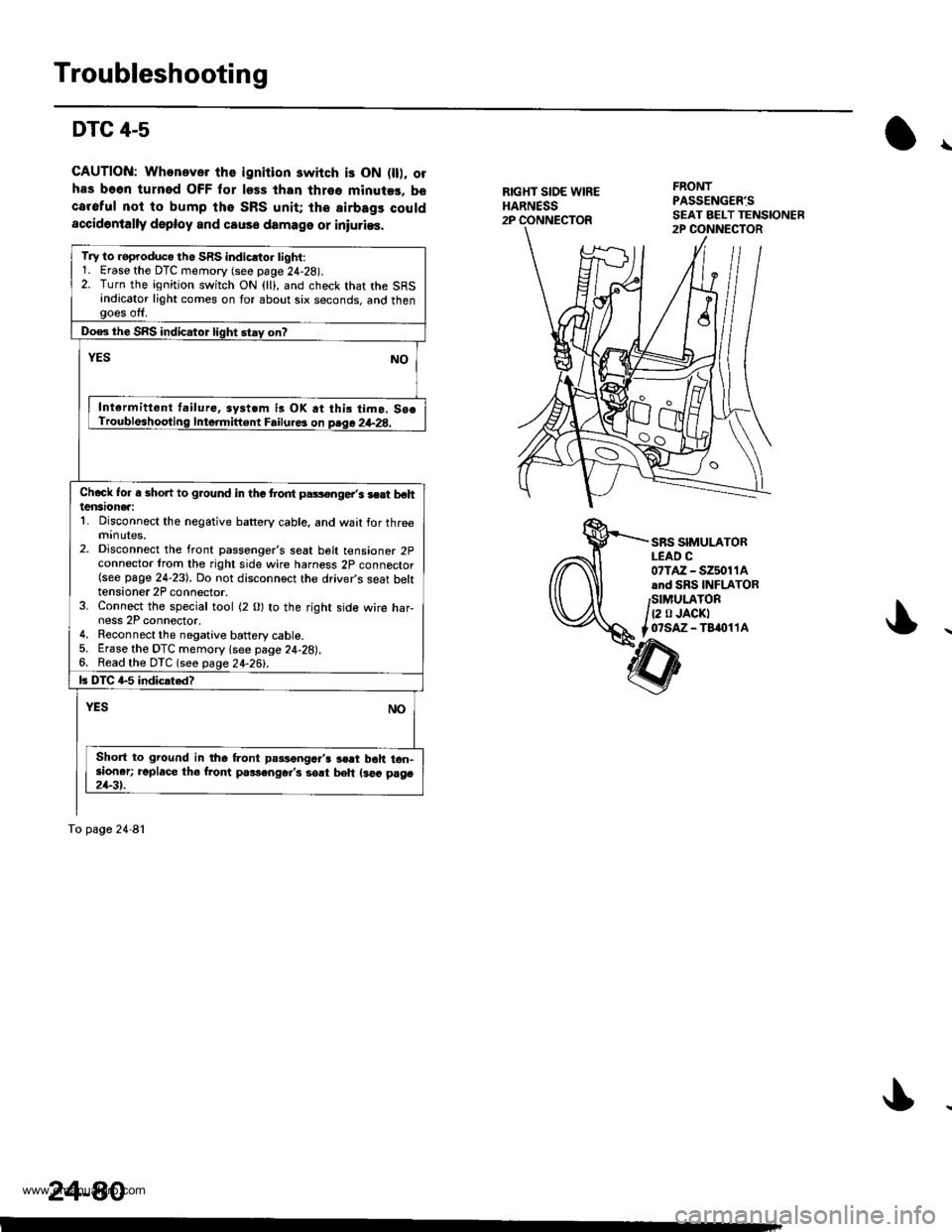
\
RIGXT SIOE WIREHARNESS2P
FRONTPASSENG€R'S
SRS SIMULATORLEAD C07lAz - s2501 1Aand SRS INFLATORSIMULATOR
t2 0 JACKTo?saz - Taaol 1A
Try to roproduco th. SRS indicrtor tighi:1. Erase the DTC memory (see page 24-28).2. Turn the ignition switch ON (ll), and check that the SRSindicator light comes on for about six seconds, and thengoes off.
Doe3 the SRS indicator light stay on?
YESNO
Int€rmittent t.ilurG, syst.m is OK at thi! timo. So€Troubleshooting Inte.mift€nt Failure3 on psqa 2+28.
Chcck Ior a shon to ground in the trodt pars€nge/s lert behtensionea:1. Disconnect the negative battery cable, and wait for threemrnutes.2. Disconnect the front passenger's seat belt tensioner 2pconnector trom the right side wire harness 2p connector(see page 24-23). Do not disconnect the driver's seat bektensioner 2P connector.3. Connect the special tool (2 0) to the right side wire har-ness 2P connector,4. Reconnect the negative battery cable.5. Erase the DTC memory lsee page 24-28).6. Read the DTC (seo page 24-26!-.
k DIC G5 indicated?
NOYES
Short to ground in the Lont passengc.'3 3€rt boh ton-sioner; replace tho from p.rlenger's sort beh ls€a page21-3t.
To page 24-81
24-80
www.emanualpro.com
Page 1378 of 1395
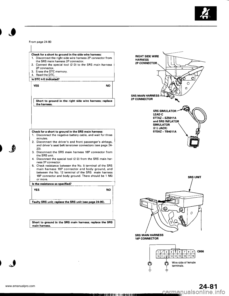
From page 24'80
Check lor a short to ground in the sido wir€ harness:1. Disconnect the rightsidewire harness 2P connector fromthe SRS main harness 2P connector.2. Connect the special tool {2 O) to the SRS main harness2P connector.3. Erase the DTC memorv.4. Read the DTC.
b DTC 4-5 indicrtad?
YESNO
Short to ground in the right side wire harness; replac.the harne3!.
Check tor a short io ground in the SRS main ha.nessi1. Disconnect the negative battery cable, and wait for threeminotes,2. Disconnect the driver's and front passenger's airbags,and driver's seat belt tonsioner connectors (see page 24-231.3. Disconnect the SRS main harness 18P connector from
4. Disconnect the special tool (2 0) from the SRS main har-ness 2P connector.5. Check resistance between the No. 5 terminal oI the SRSmain harness 18P connector and body ground, andbetween the No. 12 terminal of the SRS main harness18P connector and body ground. There should be 1 M0or more,
b th€ re3i3tance as specified?
NOYES
Faulty SRS unit replace the SRS unit {see pace 2a-951.
Short to ground in the SRS main harness; replace the SRSmain harnoss.
RIGHT SIDE WIREHARNESS2P CONNECTOR
SRS MAIN HARNESS2P CONNECTOR
SRS SIMULATORLEAD C07TAz - SZ5011Aand SRS INFLATORSIMULATOR \{2 0 JACK} \07SAZ-TB,O114 \I
ffi
)
SRS MAIN HANNESS18P CONNECTOR
24-81
www.emanualpro.com
Page 1384 of 1395
Driver's Airbag
1.
Replacement
After a collision in which the airbags were deployed, the
airbags, the seat belt tensioners (if so equipped), and
the SRS unit must be replaced.
@ Store a removed airbag with the pad su.-
tacs up, lf th€ airbag is improperly stored face down.
accidental deployment could propal the unit with
enough forc€ io causg serioug iniury.
CAUTION:
. Always disconnoct the drivor's airbag connector
when the SRS main harness is disconnactod.
. Do not disassemble or tamper with ihe airbag.
NOTE:
Do not install used SRS parts from another vehicle,
When repairing, use only new SRS parts.
Carefully inspect the airbag before you install it. Do
not install an airbag that shows signs of being
dropped or improperly handled, such as dents, cracks
or deformation.
Disconnect the battery negative cable, then discon-
nect the positive cable from the battery, and wait at
least three minutes.
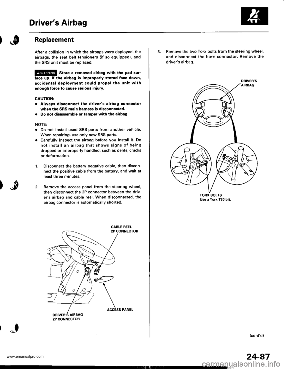
Remove the access panel from the steering wheel.
then disconnect the 2P connector between the driv-
er'6 airbag and cable reel. When disconnected. the
airbag connector is automatically shorted.
2P CONNECTON
ACCESS PANEL
24-87
3. Remove the two Torx bolts from the steering whsel,
and disconnect the horn connector. Remove the
driver's airbag,
(cont'd)
DRIVER'S
www.emanualpro.com
Page 1386 of 1395
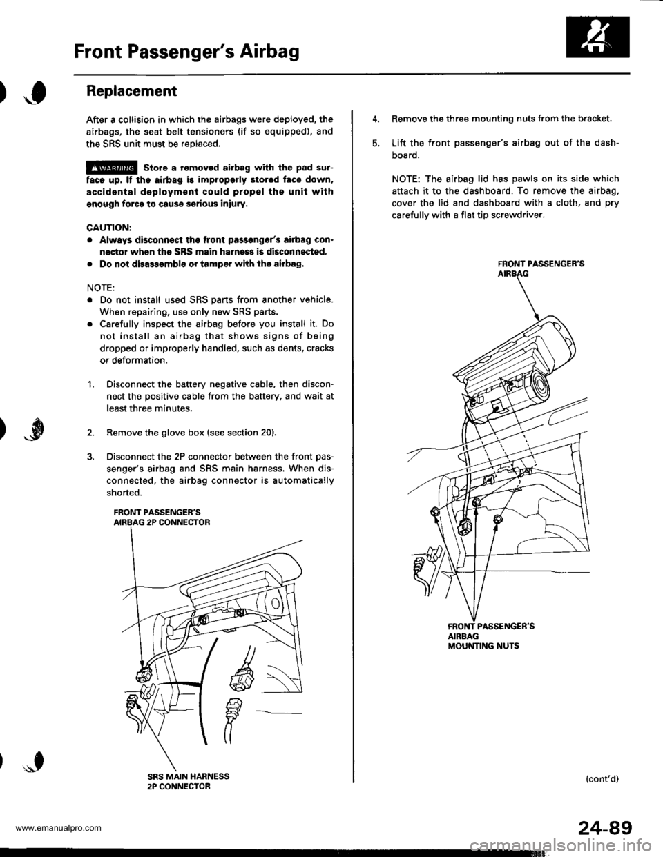
Front Passenger's Airbag
Replacement
After a collision in which the airbags were deployed, the
airbags, the seat belt tensioners (if so equipped), and
the SRS unit must be reolaced.
@ store a rsmovod airbag with lhe pad sur-
face up, It the airbag is improporly stor6d face down,
accidental doploym€nl could propsl ths unit withgnough forco to cause serious iniury.
CAUTION:
. Always disconnsqt the front pa3s6ng6r'3 airbag con-
noctor when tho SRS main harness is disconnocted,
. Do not disassambl6 or tamper with tho airbag,
NOTE:
. Do not install us6d SRS parts from another vehicle.
When repairing, use only new SRS parts.
. Carefully inspect the airbag before you install it. Do
not install an airbag that shows signs of being
dropped or improperly handled, such as dents, cracks
or deformation.
Disconnect the battery negative cable, then discon-
nect the positive cable from the battery. and wait at
least three minutes.
Remove the glove box (see section 20).
Disconnect the 2P connector between the front Das-
senger's airbag and SRS main harness, When dis-
connected, the airbag connector is automatically
shorted.
FRONT PASSENGER'S
1.
5.
Remove the three mounting nuts from the bracket.
Lift the front passsnger's airbag out of the dash-
DOaro.
NOTE: The airbag lid has pawls on its side which
attach it to the dashboard. To remove the airbag,
cover the lid and dashboard with a cloth, and pry
carefullv with a flat tip screwdriver.
FRONT PASSENGER'S
FRONT PASSENGER'SAIRBAGMOUNNNG NUTS
(cont'd)
24-49
www.emanualpro.com
Page 1392 of 1395
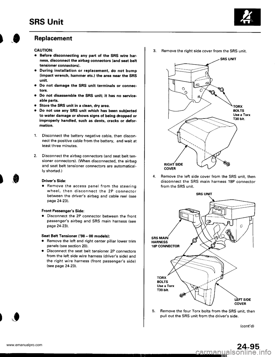
SRS Unit
).0Replacement
CAUTION:
. Before disconnecting any part of the SRS wire har-
nesg, disconnect the airbag connoctors (and soat beh
tensioner connectorsl.
. During installation or replacament, do not bump(impact wrench, hammer etc.) the area near the SRS
unit.
Do not damage the SFS unit terminalg or connsc-
lors.
Do not disassemble the SRS unit it has no saryice-
able parts,
Store the SRS unit in a clean, dry area.
Do not use any SRS unit which has been subiected
to water damage or shows signs ot being dropped orimproperly handlgd, such as dents, cracks or defor-
mation.
Disconnect the battery negative cable, then discon-
nect the positive cable from the battery, andwaitat
least three minutes.
Disconnect the airbag connectors (and seat belt ten-
sioner connectors). (When disconnected, the airbag
and seat belt tensioner connectors are automatical-
ly shorted.)
Driver's Side:
. Remove the access panel from the steering
wheel, then disconnect the 2P connector
between the driver's airbag and cable reel (see
page 24-231.
Front Passenger's Side:. Disconnect the 2P connector between the frontpassenger's airbag and SRS main harness (see
page 24-231.
Soat Beh Tensionor ('98 - 00 modelsr:. Remove the left and right center pillar lower trimpanels (see section 20).
. Disconnect the seat belt tensioner 2P connectors
from the left side wire harness (driver's side) and
the right wire harness (front passenger's side)(see page 24'231.
2.
a
a
'1.
)
)o
24-95
3. Remove the right side cover from the SRS unit.
SRS UNIT
TORXAOLTSUse a TorxT30 bir.
COVER
Remove the left slde cover from the SRS unit. then
disconnect the SRS main harness 18P connector
from the SRS unit.
sRsHARNESS18P CONNECTOR
TORXBOLTSUs€ a TorxT30 bir.
stoECOVER
Remove the four Torx bolts from the SRS unit. then
oull out the SRS unit from the driver's side.
(cont'd)
www.emanualpro.com