front HONDA CR-V 1998 RD1-RD3 / 1.G Workshop Manual
[x] Cancel search | Manufacturer: HONDA, Model Year: 1998, Model line: CR-V, Model: HONDA CR-V 1998 RD1-RD3 / 1.GPages: 1395, PDF Size: 35.62 MB
Page 1043 of 1395
Seats
Front Seat Cover Replacement (cont'dl
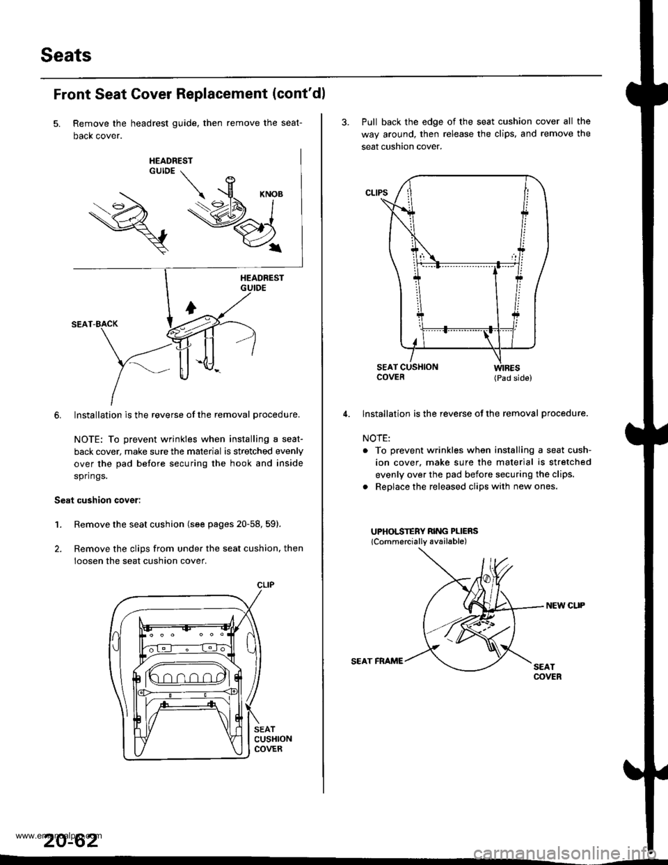
Remove the headrest guide, then remove the seat-
Dacx cover.
6. Installation is the reverse of the removal procedure.
NOTE: To prevent wrinkles when installing a seat-
back cover, make sure the material is stretched evenly
over the pad before securing the hook and inside
springs.
Seat cushion cover:
1.Remove the seat cushion (see pages 20-58, 59).
Remove the clips from under the seat cushion. then
loosen the seat cushion cover.
SEATCUSHIONCOVER
20-62
CLIP
3. Pull back the edge of the seat cushion cover all the
way around, then release the clips. and remove the
seat cushion cover.
COVER (pad side)
lnstallation is the reverse of the removal procedure.
NOTE:
. To prevent wrinkles when installing a seat cush-
ion cover. make sure the material is stretched
evenly over the pad before securing the clips.
. Replace the released clips with new ones.
UPHOLSTERY RING PLIERS
lCommercially available)
NEW CUP
SEAT FRAME
www.emanualpro.com
Page 1053 of 1395
Bumpers
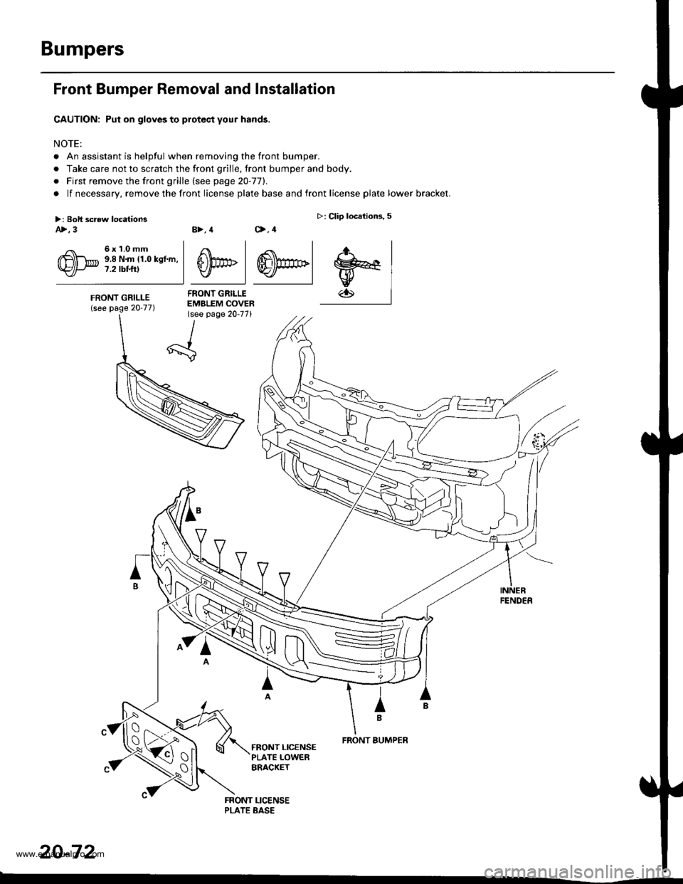
Front Bumper Removal and Installation
CAUTION: Put on gloves to protec,t your hands.
NOTE:
. An assistant is helpful when removing the front bumper.
. Take care not to scratch the front grille, lront bumper and body.
o First remove the front grille (see page 20-77).
. lf necessary, remove the front license plate base and front license plate lower bracket.
B>, 4 C>,4
4 .<\l
S))PF | ffi)m>lv I Y./ |
FRONT GRILLEEMBLEM COVER(see page 20-77)
>: Clip locations,5
.r., I
w€lw
FENDER
IB
FRONT BUMPER
20-72
>: Boli screw locationsA>,3
6x1.0mm9.8 N.m (1.0 kgf.m,7.2 tbt t0
FRONT GRILLE(see page 20-77)
tx -
\{_:
www.emanualpro.com
Page 1054 of 1395
A>, 5 V.2
>: Clip locationsA>, 5 B>.3
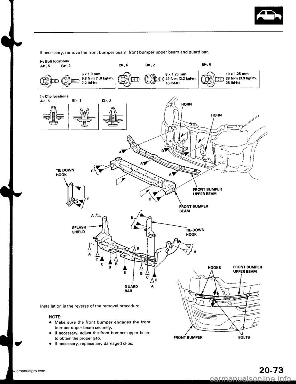
lf necessary, remove the front bumper beam, front bumper upper beam and guard bar.
>: Boh locationsc>.6D>,2E>,6
TIE DOWNHOOK
Yl- r
{to/
Installation is the reverse ot the removal procedure.
NOTE:
. Make sure the front bumper engages the front
bumper upper beam securely.
. It necessary, adjust the front bumper upper beam
to obtain the proper gap.
. lf necessary, replace any damaged clips.
Gfu @p;i,li',ll-"-'
TIE.DOWNHOOK
v1
10 x 1.25 mm38 N.rn {3.9 kgf.m,28 rbl.ftl
@,,2
nln-nlznr I
dE6 I #\Er+ | ;lHl= |€ =.=r t:Wl
BEAM
FRONT BUMPEB
20-73
www.emanualpro.com
Page 1057 of 1395
Hood
Adjustment
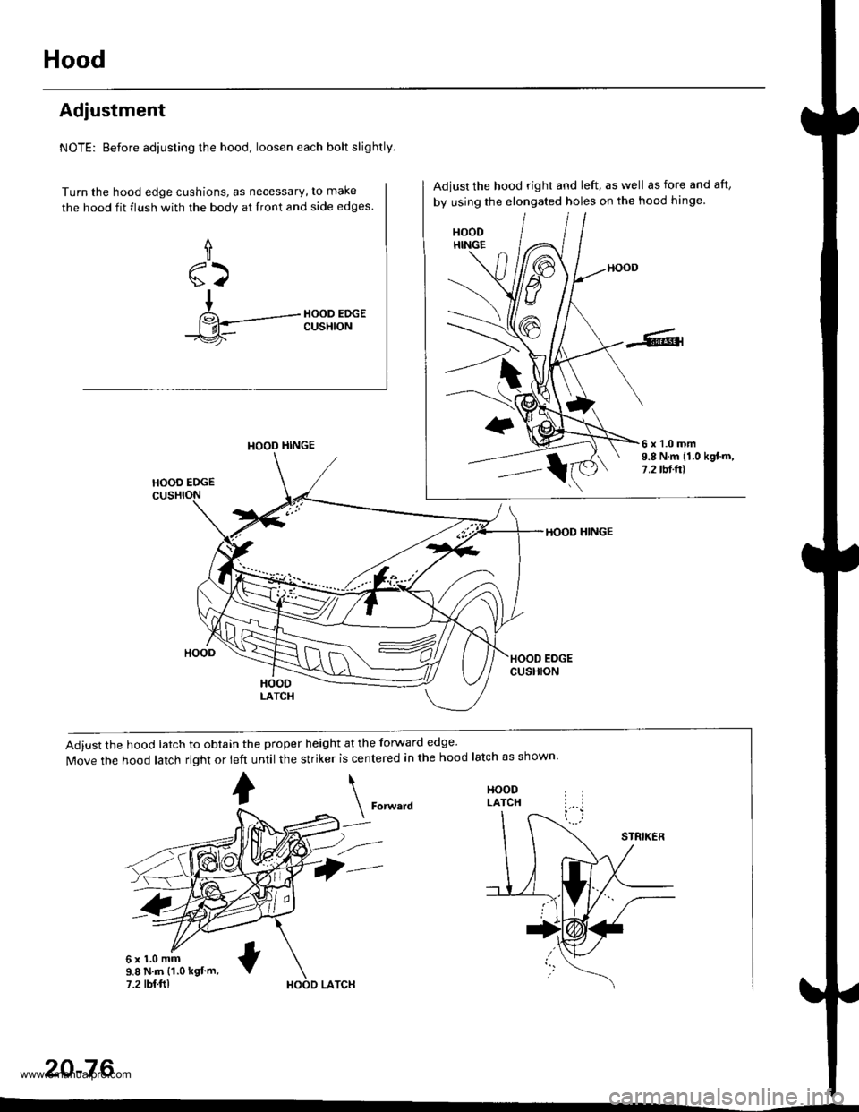
NOTE: Before adjusting the hood, loosen each bolt slightly.
Turn the hood edge cushions, as necessary, to make
the hood fit flush with the bodv at front and side edges.
f
sz
+
14---+ik-
HOOD EDGECUSHION
Adiust the hood latch to obtain the proper height at the forward edge'
Move the hood latch right or left until the striker is centered in the hood latch as shown
HOOD HINGE
\
?--
HOODLATCH
9.8 N.m (1.0 kgf m,
7.2 rbf.ftlHOOD LATCH
20-76
Adjust the hood right and left, as well as fore and aft,
by using the elongated holes on the hood hinge
6x1.0mm9.8 N.m (1.0 kgtm,7 .2 tbt.ttl
HOOD HINGE
www.emanualpro.com
Page 1058 of 1395
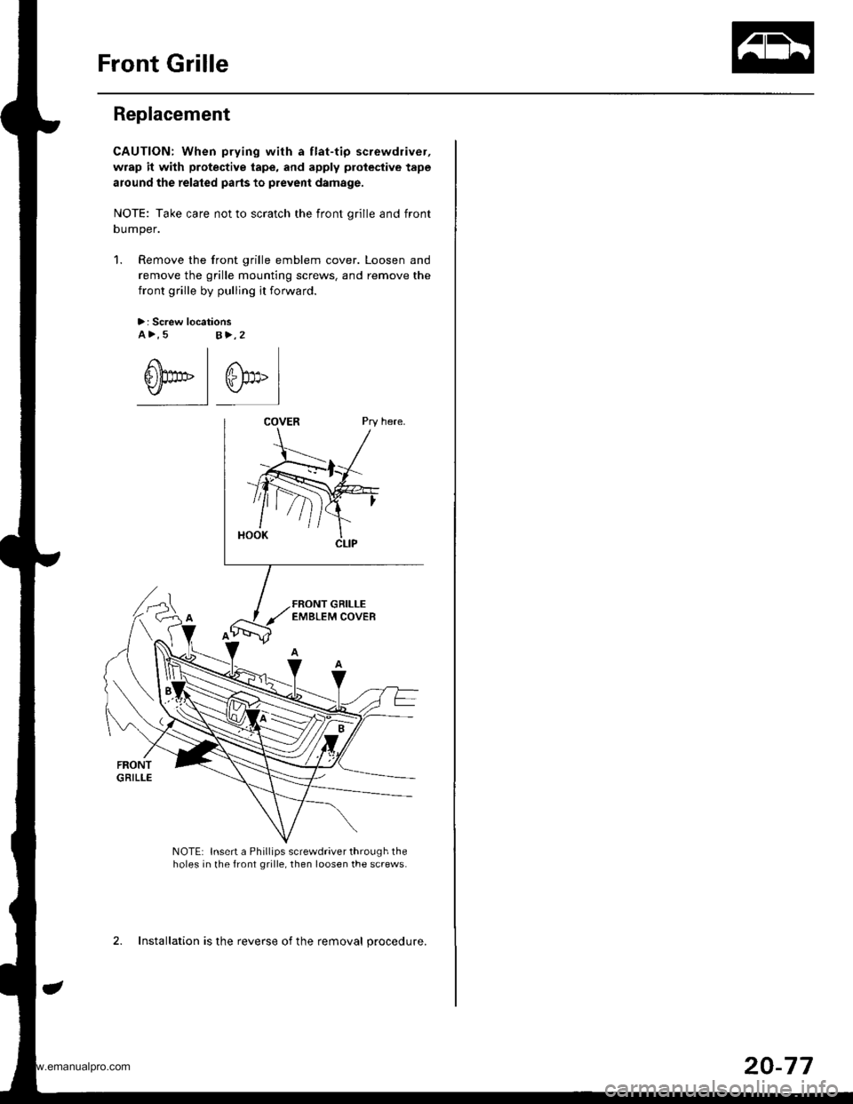
Front Grille
Replacement
CAUTION: When prying with a flat-tip screwdriver,
wrap it with protective tape, and apply protective tape
around the related parts to prevent damage.
NOTE: Take care not to scratch the front orille and front
oumper.
1. Remove the front grille emblem cover. Loosen and
remove the grille mounting screws. and remove the
front grille by pulling it forward.
>: Screw locationsa>,5s>,2
@-l @,"l
NOTE: Insert a Phillips screwdriver through theholes in the front grille, then loosen the screws.
2. Installation is the reverse of the removal procedure.
20-77
www.emanualpro.com
Page 1065 of 1395
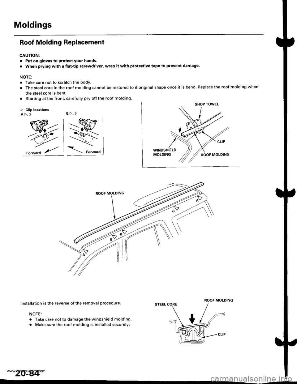
Moldings
Roof Molding Replacement
CAUTION:
. Put on glovgs to protect your hands.
. Wh€n prying with a {lat-tip screwdriver, wrap it whh protective tape to prevent damage
NOTE:
. Take care not to scratch the body.
. The steel core in the roof molding cannot be restored to it original shape once it is bend. Replace the roof molding when
the steel core is bent.
. Starting at the front, carefully pry off the roof molding.
>: Clip locationsA>,2
ROOF MOLDINGInstallation is the reverse of the removal procedure.
NOTE:
. Take care not to damage the windshield molding.
. Make sure the roof molding is installed securely.
STEEL CORE
B>,3
20-84
www.emanualpro.com
Page 1066 of 1395
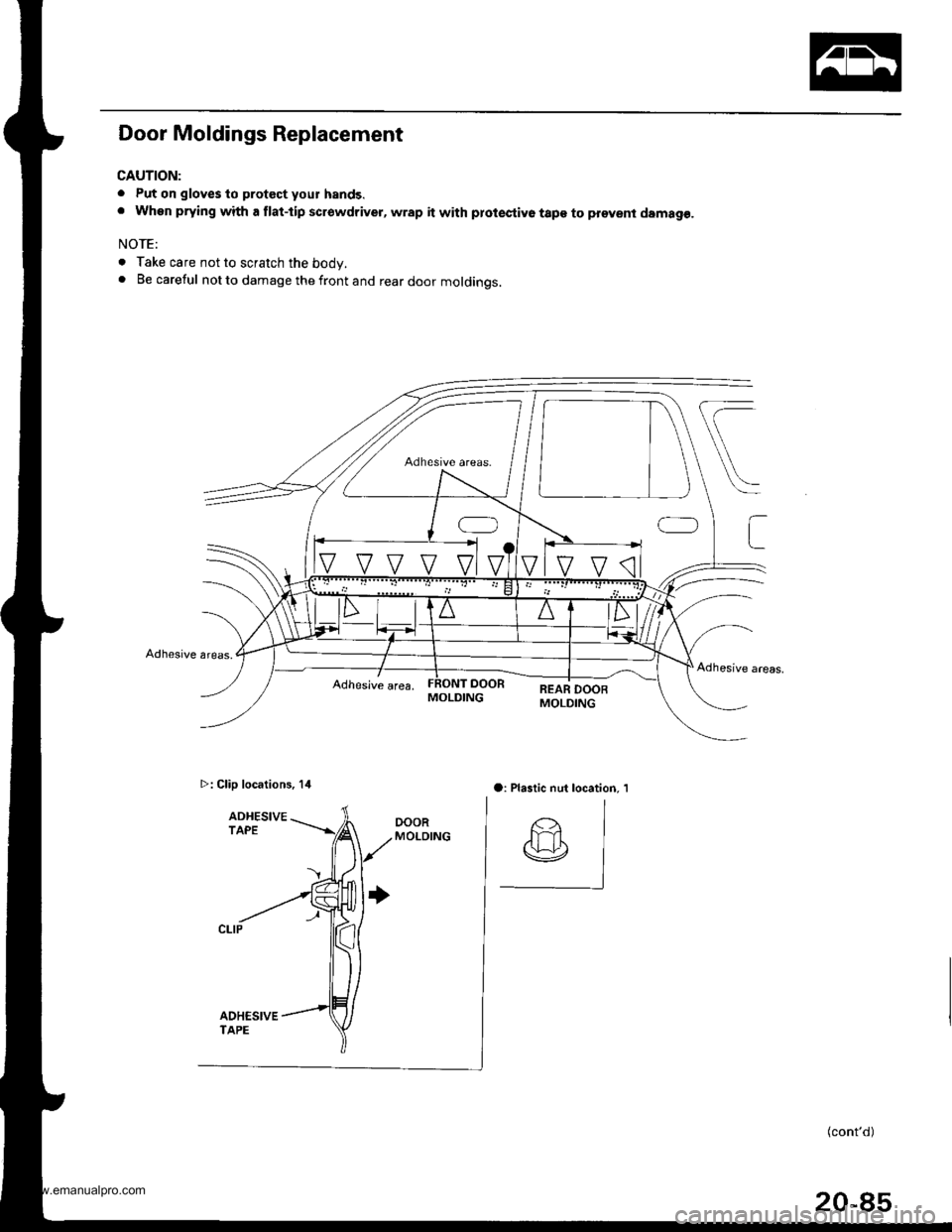
Door Moldings Replacement
CAUTION:
. Put on gloves to protect your hands.. When prying with a flat-tip scrowdriver, wrap it with prot€stive tape to provent damag€.
NOTE:
. Take care not to scratch the body.. Be careful not to damage the front and rear door moldings.
t
Adhesive aleas,
Adhesive area.FRONT DOORMOLDINGREAR DOOBMOLDING
a: Plastic nut location, 1
(cont'd)
20-85
>: Clip locations, 14
www.emanualpro.com
Page 1067 of 1395
Moldings
Door Moldings Replacement (cont'd)
It the old molding is to be reinstalled:
The following materials and tools are required to repair
the molding.
NOTE: Followthe manufacturer's instructions.
Materials: (Reference)
. Stripe remover
3M 08907
. Stripe adhesive remover
3M 08908
. Adhesive tape
3M Super Automotive Attachment Tape
Tools:
. Protective tape
. Knife or Cutter
. Sponge or Shop towel
. Infrared dryer
. Film
. Plastic putty knife
. Alcohol
CAUTION: Put on gloves to protect your hands,
1. lf necessary, replace any damaged clips on the mold-
ang.
2. Apply the stripe remover evenly to the bonding sur-
face of the body and molding.
3. Cover the bonding surface of the body and molding
with a film, then heat to 104 - 122"F (40 - 50'C) for 5- 10 minutes with an infrared dryer.
NOTE: Use care when heating to prevent deforma-
tion of the body and molding.
4. Carefully scrape the adhesive tape with a plastic
putty knife.
For removal of adhesive tape residue, follow-up with
stripe adhesive remover, then scrape the adhesive
tape with a plastic putty knife.
Remove the protective tape, then clean the bonding
surface with a sponge dampened in alcohol.
NOTE: Make sure the bonding surface is kept free or
water, oil and grease.
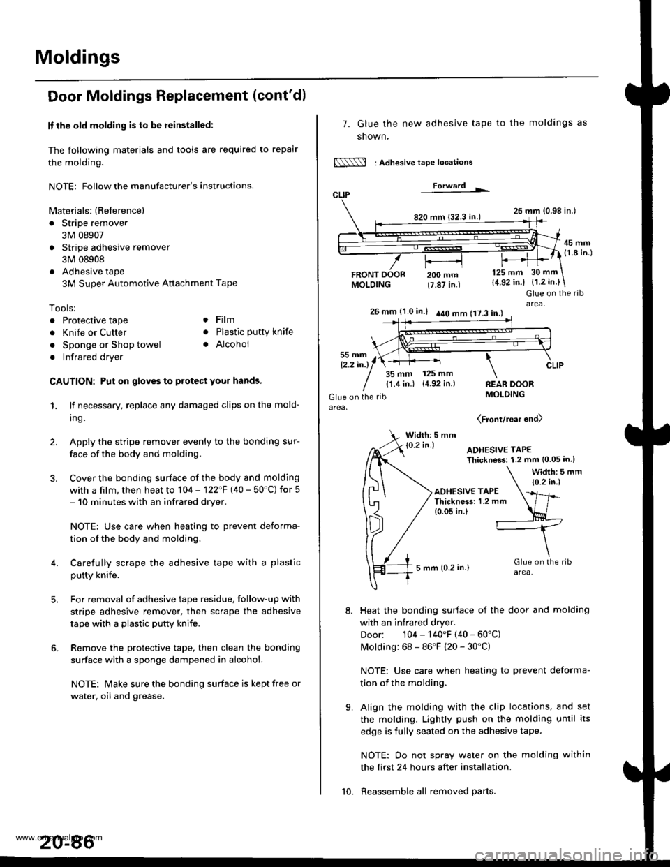
7. Glue the new adhesive tape
snown,
N : Adlesive tape locations
Forwerd L
820 mm 132.3 in.)
FRONTMOLDING
to the moldings as
25 mm {0.98 in.l
45 mm(1.8 in.l
200 mm(7.87 in.)
125 mm
{4.92 in.)30 mm
{1.2 in.}
t'.
Glue on the ribarea,26 mm (1.0 in.) 440 mm 117.3 in.l
35 mm 125 mm
{1.4 in.) {4.92 in.)REAR DOORMOLDING
(Front/rear end)
Width: 5 mm
Heat the bonding surface of the door and molding
with an infrared dryer.
Door: 104 - 140'F (40 - 60'C)
Molding: 68 - 86'F (20 - 30'C)
NOTE: Use care when heating to prevent deforma-
tion of the molding.
Align the molding with the clip locations, and set
the molding. Lightly push on the molding until its
edge is fully seated on the adhesive tape.
NOTE: Oo not spray water on the molding within
the first 24 hours after installation.
Reassemble all removed parts.10.
www.emanualpro.com
Page 1070 of 1395
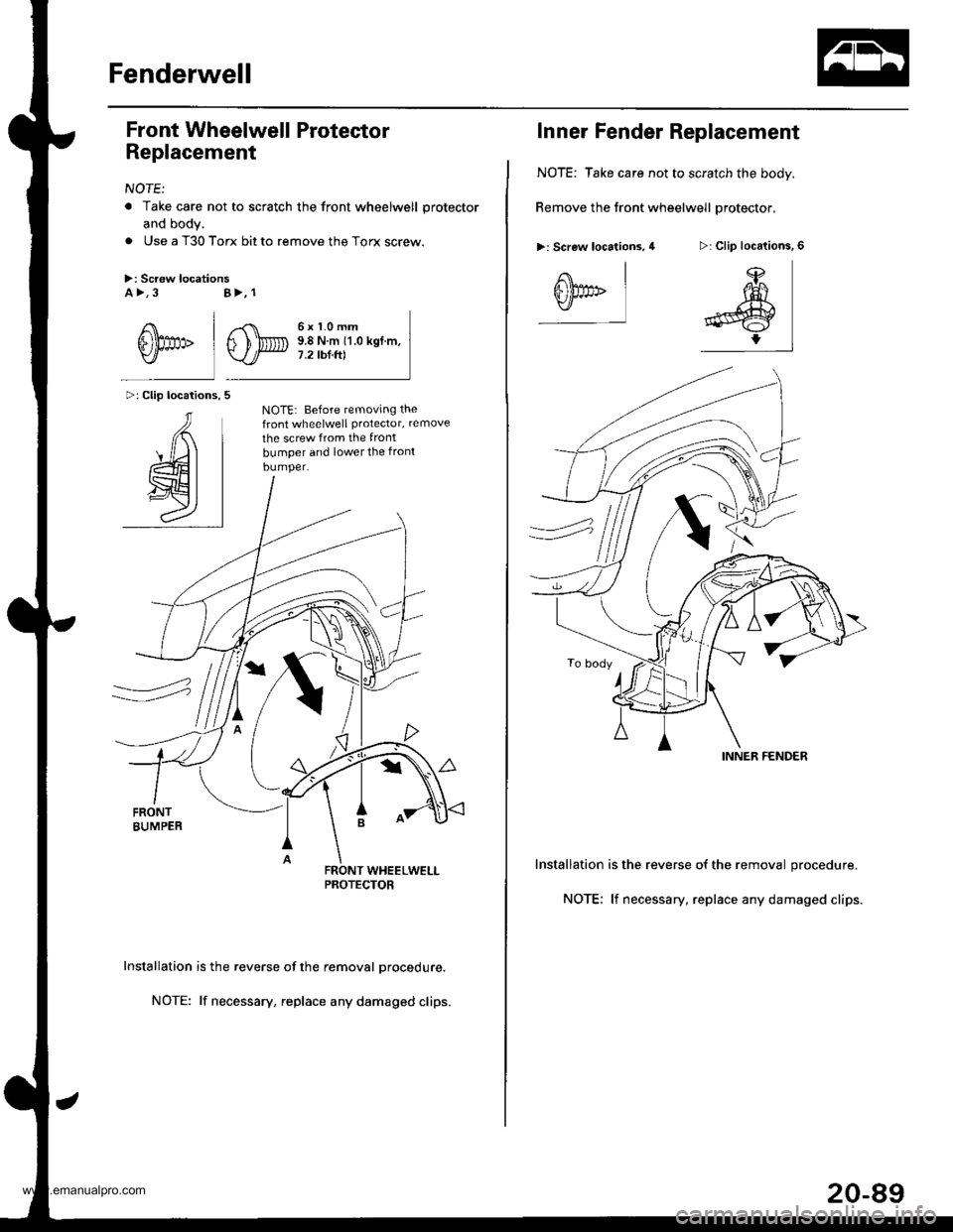
Fenderwell
Front Wheelwell Protector
Replacement
NOTE:
a Take care not to scratch the front wheelwell protector
and body.
. Use a T30 Torx bit to remove the Torx screw.
>: Screw locationsa >,3
/\l
6'thp IY/
>: Clip locations,
AI
4t I
wt I
al
B>, 1
,,-C\
s)Dv.l/
6x1.0mm9.8Nm(1.0kgf.m,7.2 tbf.ft)
NOTE: Before temoving thefront wheelwell Protector, remove
the screw from the front
bumper and lower the front
bumper.
Installation is the reverse of the removal Drocedure.
NOTE: lf necessary, replace any damaged clips.
Inner Fender Replacement
NOTE: Take care not to scratch the body.
Remove the front wheelwell protector,
>: Screw locations, 4
Installation is the reverse of the removal procedure.
NOTE; lf necessary, replace any damaged clips.
>: Clip locations,
ffi)fl(
l#:rl
A\
s))pp>Y]
INNER FENDER
20-89
www.emanualpro.com
Page 1074 of 1395
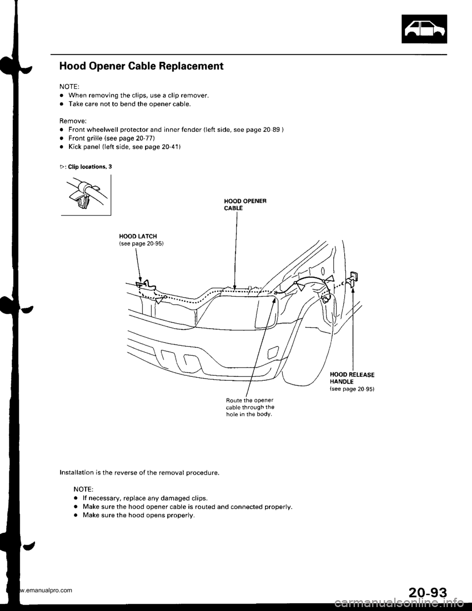
Hood Opener Cable Replacement
NOTE:
. When removing the clips, use a clip remover.
. Take care not to bend the opener cable.
Remove:
. Front wheelwell protector and inner fender {left side, see page 20 89}
. Front grille (see page 20-77)
. Kick panel (left side. see page 20-411
HOOD LATCH(see page 20-95)
Route the openercable through thehole in the body.
>: Clip locations,3
'.--)r I
@l
Installation is the reverse of the removal procedure.
NOTE:
. lf necessary. replace any damaged clips.
. Make sure the hood opener cable is routed and connected properly.
. Make sure the hood opens properly.
t"
HOOD RELEASEHANDLE(see page 20 95)
www.emanualpro.com