Oil HONDA CR-V 1998 RD1-RD3 / 1.G Workshop Manual
[x] Cancel search | Manufacturer: HONDA, Model Year: 1998, Model line: CR-V, Model: HONDA CR-V 1998 RD1-RD3 / 1.GPages: 1395, PDF Size: 35.62 MB
Page 954 of 1395
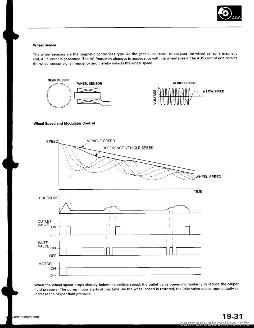
Wheel Sensor
The wheel sensors are the magnetic contactless type. As the gear pulser teeth rotate past the wheel sensor's magnetic
coil, AC current is generated. The AC frequency changes in accordance with the wheel speed. The ABS control unit detects
the wheel sensor signal frequency and thereby detects the wheel speed
at LOW SPEED
wheel Sp€od and Modulatot Control
VEHICLE SPEED
VEHICLE SPEED
WHEEL SPEED
PRESSU
OUTLETVALVE ON
OFF
INLETVALVE ON
OFF
MOTOR
ON
OFF
When the wheel speed drops sharply below the vehicle speed, the outlet valve opens momentarily to reduce the caliper
fluid pressure. The pump motor starts at this time. As the wheel speed is restored. the inlet valve opens momentarily to
increase the caliDer fluid oressure.
F
GEAR PULSER
19-31
www.emanualpro.com
Page 1012 of 1395
7.
8.
Using a knife, scrape the old adhesive smooth to a
thickness of about 2 mm (0.08 in.) on the bonding
surface around the entire windshield opening flange.
NOTE:
a Do not scrape down to the painted surface of the
body; damaged paint will interfere with proper
bonding.
. Remove the rubber dams and fasteners from the
oooy,
. Mask off surrounding surfaces before painting.
Clean the body bonding surface with a sponge damp-
ened in alcohol.
NOTE: After cleaning, keep oil, grease and water
from getting on the surface.
lf the old windshield is to be reinstalled, use a putty
knjfe to scrape off all traces of old adhesive and the
rubber dams, then clean the windshield surface
with alcohol where new adhesive is to be applied.
NOTE: Make sure the bonding surface is kept free
of water, oil and grease.
CAUTION: Avoid setting tho windshield on its edges;
small chips m8y later devolop into cracks.
NOTE: Clean the shadowed area.
9.
WINDSHIELD
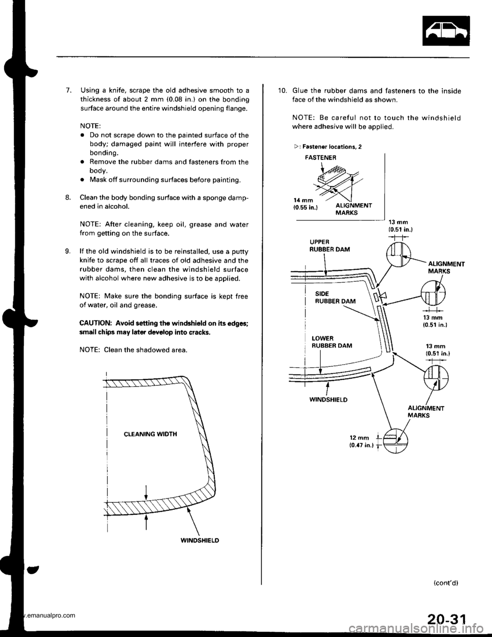
10. Glue the rubber dams and fasteners to the inside
face of the windshield as shown
NOTE: Be careful not to touch the windshield
where adhesive will be applied,
13 mm(0.51 in.)--r-r
>r Fastener locrtions. 2
FASTENEB
\,@,--
w,{,.'>Yl
14 mm -'- \l0.55 in.l ALIGNMENTMARKS
ALIGNMENTMARKS
13 mm(0.51 in.l
13 mm10.51 in.)*ffi
ALIGNMENTMARKS
12 mm(0.47 in.l
(cont'd)
20-31
www.emanualpro.com
Page 1017 of 1395
Glass
v\//,/6 /l
Ouarter Glass Replacement (cont'd)
lnside:
ADHESIVE
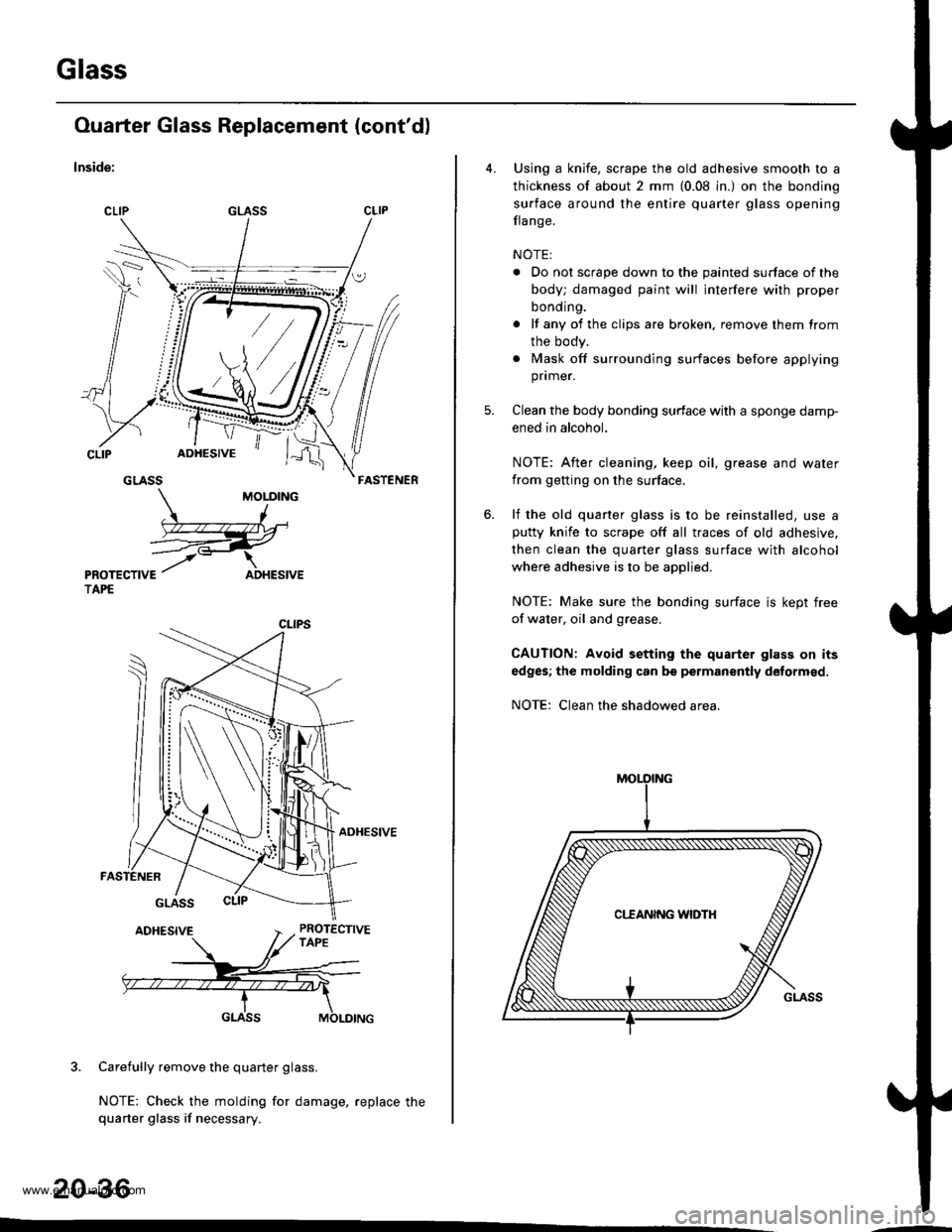
3. Carefully remove the quarter glass.
NOTEj Check the molding for damage, replace thequa.ter glass if necessary.
20-36
Using a knife, scrape the old adhesive smooth to a
thickness of about 2 mm (0.08 in.) on the bonding
surface around the entire quarter glass opening
flange.
NOTE:
. Do not scrape down to the painted surface of the
body; damaged paint will interfere with proper
bond ing.
. lf any of the clips are broken. remove lhem trom
the body.
. Mask off surrounding surfaces before applying
pnmer.
Clean the body bonding surface with a sponge damp-
ened in alcohol.
NOTE: After cleaning, keep oil, grease and water
from getting on the surface.
lf the old quarter glass is to be reinstalled, use aputty knife to scrape off all traces of old adhesive,
then clean the quarter glass surface with alcohol
where adhesive is to be applied.
NOTE: Make sure the bonding surface is kept free
of water, oil and grease.
CAUTION: Avoid setting the quarter glass on its
edges; the molding can be permanently detormed.
NOTE: Clean the shadowed area.
www.emanualpro.com
Page 1059 of 1395
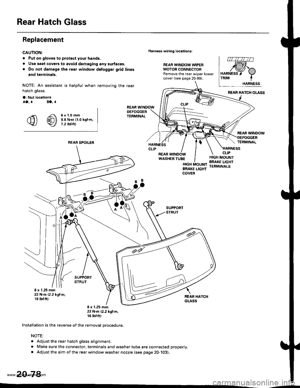
Rear Hatch Glass
Replacement
CAUTION:
. Put on gloves to protecl your hands.
. Use seal covers to avoid damaging any surfaces.. Do not damage the rear window delogger grid lines
and terminals.
NOTE: An assistant is helpful when removing the rear
hatch glass.
a: Nul locationsAa.4 Ba.4
€ @ i!iff*-"-
Harnoss wiring locations:
REAR WINDOW WIPERMOTOR CONNECTORRemove the rear wiper lowercover (see page 20-99i.
HARNESS 'TRIM
.;=-
8 x 1.25 mm22 N-m l'2.2 kgl.m,'16 tbt fr)
8 x 1.25 mm22N.m l.2.2*ql.m,16 tbf.ft|
Installation is the reverse of the removal orocedure.
NOTE:
. Adjust the rear hatch glass alignment.
. Make sure the connector, terminals and washer tube are connected properly.
. Adjust the aim of the rear window washer nozzle (see page 20-103).
20-78
REAR SPOILER
'--
www.emanualpro.com
Page 1060 of 1395
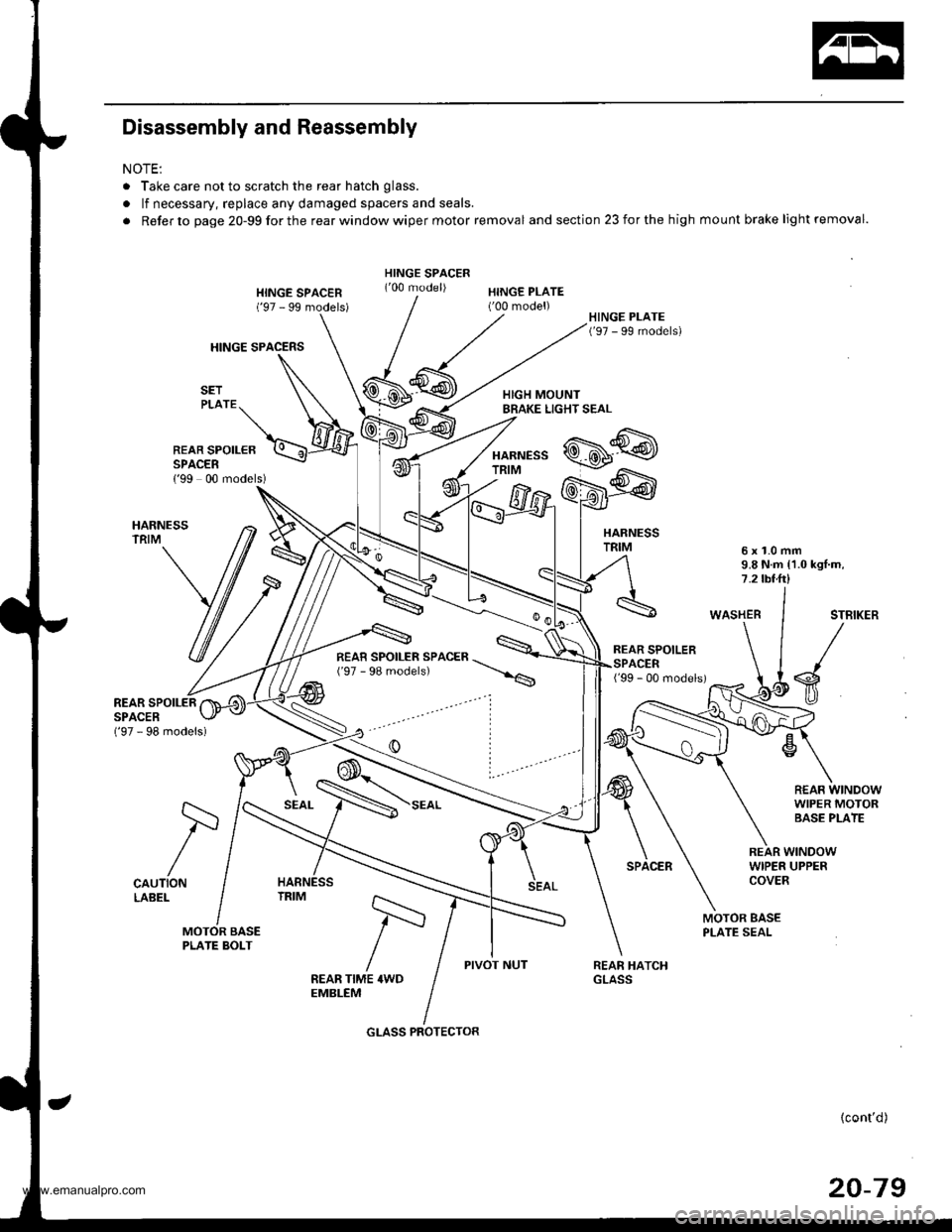
Disassembly and Reassembly
NOTE:
. Take care not to scratch the rear hatch glass.
. lf necessary, replace any damaged spacers and seals.
. Refer to page 20-99forthe rearwindowwiper motor removal and section 23 for the high mount brake light removal.
HINGE SPACERS
HINGE SPACEN('97 - 99 models)HINGE PLATE('00 model)
HARNESSTRIM
REAR SPOILEBSPACER{'99 00 models)
HARNESSTRIM6x1.0mm9.8 N.m {1.0 kgl.m,7.2 tbt.ft)
WASHERSTBIKER
s
R€AF WINDOWWIPER MOTORBASE PLATE
('97 - 98 models)
REAR SPOILERSPACER
CAUTIONLABEL
SEAL
REAR WINDOWWIPER UPPERCOVER
MOTOR BASEPLATE SEAL
PIVOT NUTFEAR TIME 4WDEMBLEM
{cont'd)
20-79
/=
GLASS PROTECTOR
www.emanualpro.com
Page 1061 of 1395
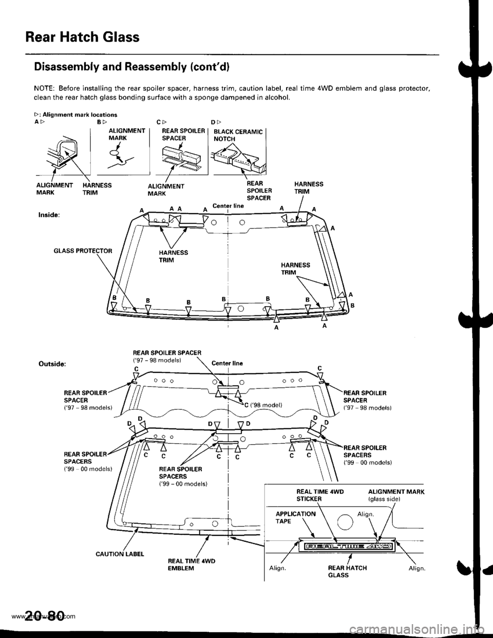
Rear Hatch Glass
l,_ | r\
wl:
f\ALIGNMENT HARNESSMARK TRIM
Disassembly and Reassembly (cont'dl
NOTE: Before installing the rear spoiler spacer, harness trim. caution label, real time 4WD emblem and glass protector,
clean the rear hatch glass bonding surface with a sponge dampened in alcohol.
>: Alignment mark locatioosA>
ALIGNMENTMARK
A Center line
lnside:
Outside:Centor line
REAR SPOILERSPACER{'97 98 models)
SPOILERREARSPACEBSSPACERS('99 00 models){'99 00 models)
20-80
REAR SPOILER SPACER
ooo O
www.emanualpro.com
Page 1062 of 1395
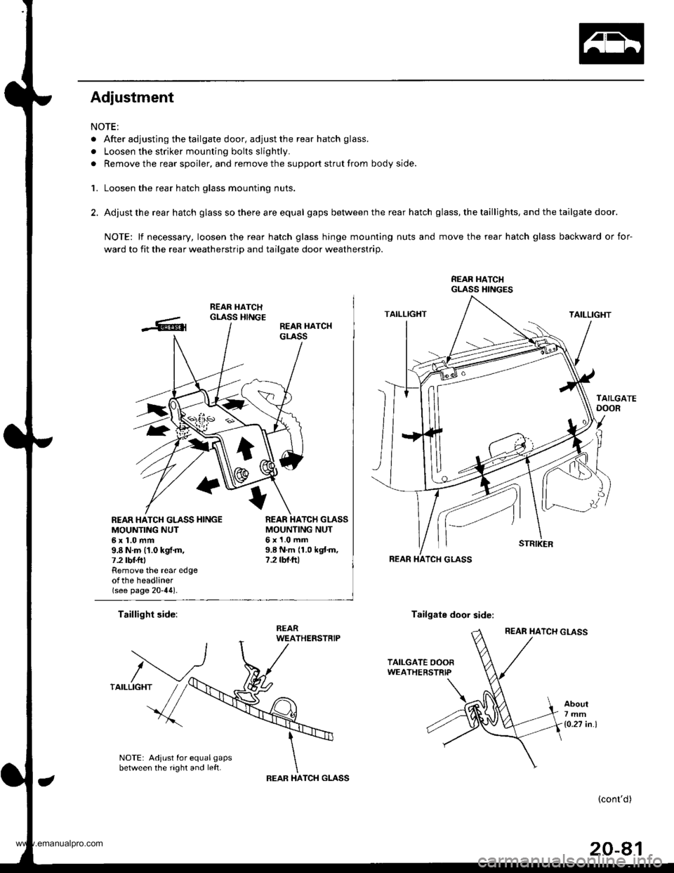
Adjustment
NOTE:
. After adjusting the tailgate door, adjust the rear hatch glass.
. Loosen the striker mounting bolts slightly.
. Remove the rear spoiler, and remove the support strut from body side.
1. Loosen the rear hatch glass mounting nuts.
2. Adjust the rear hatch glass so there are equal gaps between the rear hatch glass, the taillights, and the tailgate door.
NOTE: lf necessary, loosen the rear hatch glass hinge mounting nuts and move the rear hatch glass backward or for-
ward to fit the rear weatherstrip and tailgate door weatherstrip.
REAR HATCI{GLASS HINGES
REAR HATCH GLASS HINGEMOUNTING NUT6x1.0mm9.8 N.m (1.0 kgf.m,7.2 tbt f Remove the rear edgeotthe headliner(see page 20-44).
MOUNTING NUT6x1.0mm9.8 N.m 11.0 kgtm,7.2 rbf.ftt
Taillight side:Tailgate door side:
About7mm
1o.27 in.l
NOTE: Adjust for equal gapsbetween the right and left.TCH GLASSIHAREAR
(cont'd)
20-81
www.emanualpro.com
Page 1063 of 1395
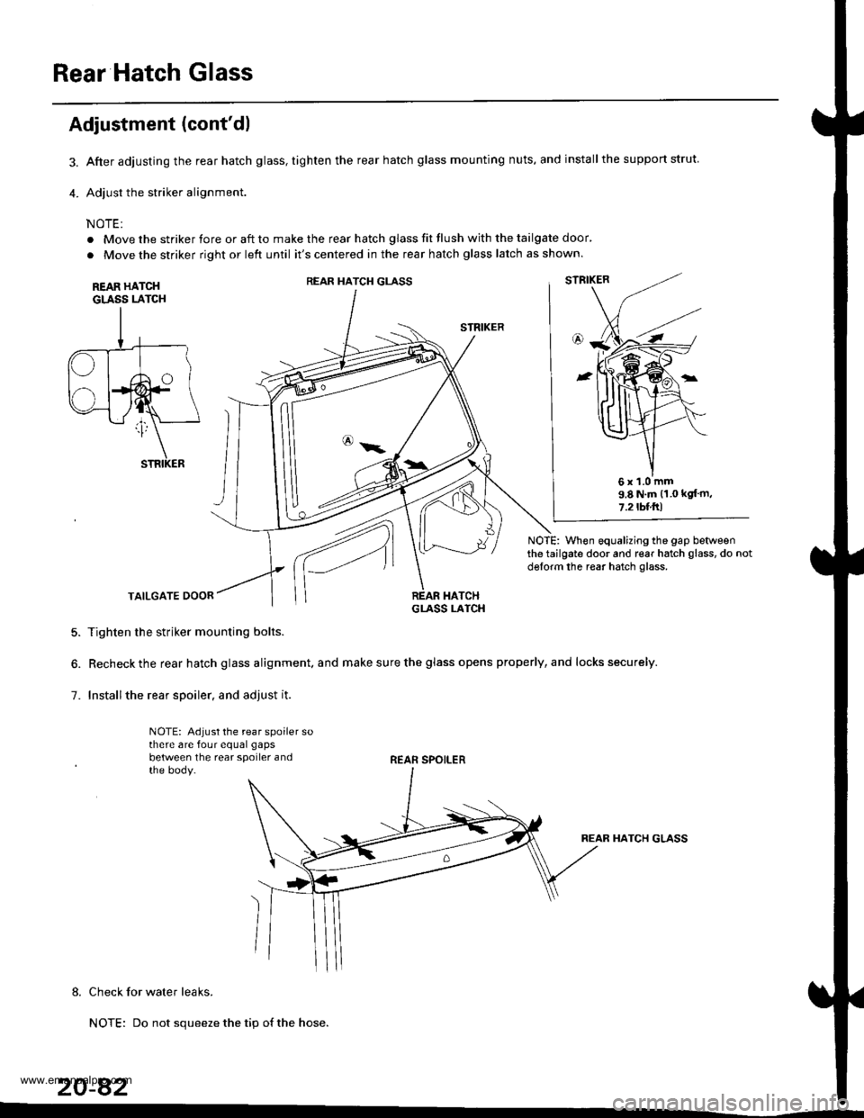
Rear Hatch Glass
3.
4.
Adjustment (cont'dl
After adjusting the rear hatch glass, tighten the rear hatch glass mounting nuts, and installthe support strut.
Adjust the striker alignment.
NOTE:
. Move the striker fore or aft to make the rear hatch glass fit flush with the tailgate door'
. Move the striker right or left until it's centered in the rear hatch glass latch as shown.
REAR HATCHGLASS LATCH
STRIKER
NOTE: When equalizing the gap betweenthe tailgate door and rear hatch glass, do notdglorm the rear hatch glass.
TAILGATE DOOR
5. Tighten the striker mounting bolts.
6. Recheck the rear hatch glass alignment. and make sure the glass opens properly, and locks securely.
7. Installthe rear spoiler. and adjust it.
NOTE: Adjust the rear spoiler sothere are four equal gaps
between the rear spoiler andthe body.REAR SPOILER
REAR HATCH GLASS
8. Check for water leaks.
NOTE: Do not squeeze the tip of the hose.
20-82
REAR HATCH GLASS
6x1.0mm9.8 N.m (1.0 kgt'm,
7.2tbl.ftl
www.emanualpro.com
Page 1067 of 1395
Moldings
Door Moldings Replacement (cont'd)
It the old molding is to be reinstalled:
The following materials and tools are required to repair
the molding.
NOTE: Followthe manufacturer's instructions.
Materials: (Reference)
. Stripe remover
3M 08907
. Stripe adhesive remover
3M 08908
. Adhesive tape
3M Super Automotive Attachment Tape
Tools:
. Protective tape
. Knife or Cutter
. Sponge or Shop towel
. Infrared dryer
. Film
. Plastic putty knife
. Alcohol
CAUTION: Put on gloves to protect your hands,
1. lf necessary, replace any damaged clips on the mold-
ang.
2. Apply the stripe remover evenly to the bonding sur-
face of the body and molding.
3. Cover the bonding surface of the body and molding
with a film, then heat to 104 - 122"F (40 - 50'C) for 5- 10 minutes with an infrared dryer.
NOTE: Use care when heating to prevent deforma-
tion of the body and molding.
4. Carefully scrape the adhesive tape with a plastic
putty knife.
For removal of adhesive tape residue, follow-up with
stripe adhesive remover, then scrape the adhesive
tape with a plastic putty knife.
Remove the protective tape, then clean the bonding
surface with a sponge dampened in alcohol.
NOTE: Make sure the bonding surface is kept free or
water, oil and grease.
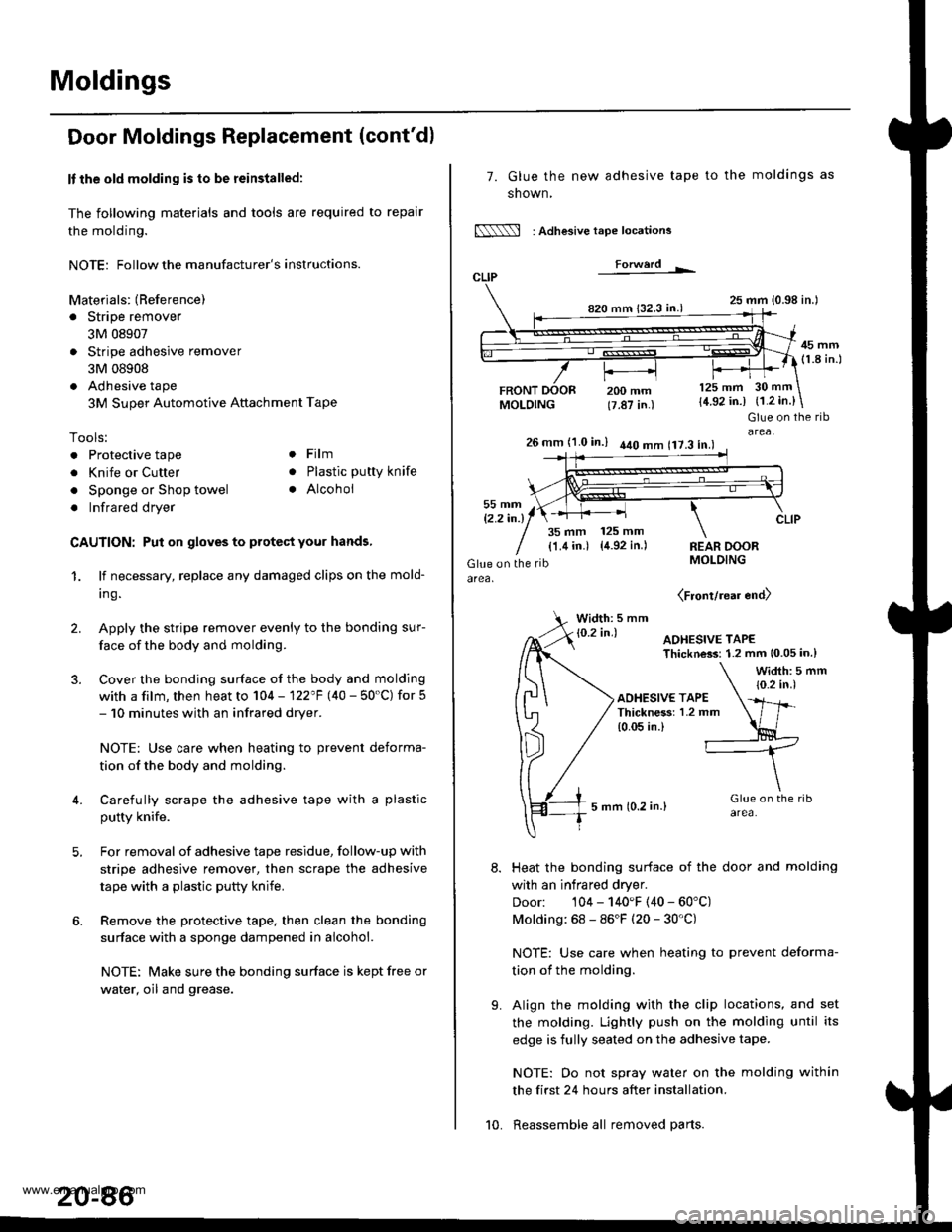
7. Glue the new adhesive tape
snown,
N : Adlesive tape locations
Forwerd L
820 mm 132.3 in.)
FRONTMOLDING
to the moldings as
25 mm {0.98 in.l
45 mm(1.8 in.l
200 mm(7.87 in.)
125 mm
{4.92 in.)30 mm
{1.2 in.}
t'.
Glue on the ribarea,26 mm (1.0 in.) 440 mm 117.3 in.l
35 mm 125 mm
{1.4 in.) {4.92 in.)REAR DOORMOLDING
(Front/rear end)
Width: 5 mm
Heat the bonding surface of the door and molding
with an infrared dryer.
Door: 104 - 140'F (40 - 60'C)
Molding: 68 - 86'F (20 - 30'C)
NOTE: Use care when heating to prevent deforma-
tion of the molding.
Align the molding with the clip locations, and set
the molding. Lightly push on the molding until its
edge is fully seated on the adhesive tape.
NOTE: Oo not spray water on the molding within
the first 24 hours after installation.
Reassemble all removed parts.10.
www.emanualpro.com
Page 1069 of 1395
Spare Tire Gover
Emblem Installation
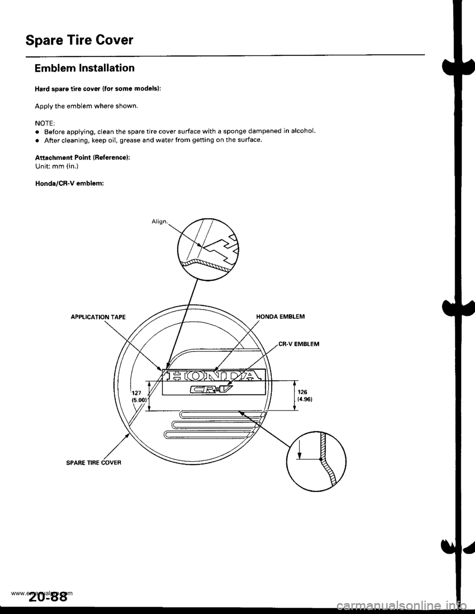
Hard spare tire cover {for some models}:
Apply the emblem where shown.
NOTE:
. Before applying, clean the spare tire cover surface with a sponge dampened in alcohol.
. After cleaning, keep oil, grease and water from getting on the surface
Attachment Point lR€ferencel:
Unit: mm (in.)
Honda/CR-v emblem:
APPLICATION TAPEHONDA EMBLEM
CR.V EMBLEM
SPARE TIRE COVEB
20-88
www.emanualpro.com