Oil HONDA CR-V 1998 RD1-RD3 / 1.G Workshop Manual
[x] Cancel search | Manufacturer: HONDA, Model Year: 1998, Model line: CR-V, Model: HONDA CR-V 1998 RD1-RD3 / 1.GPages: 1395, PDF Size: 35.62 MB
Page 752 of 1395
Transfer Assembly
Disassembly (cont'd)
7.
Secure the transfer housing in a bench vise withsoft iaws. To prevent damage to the transfer hous-ing, always use soft jaws or equivalent materials
between the transfer housing and the vise.
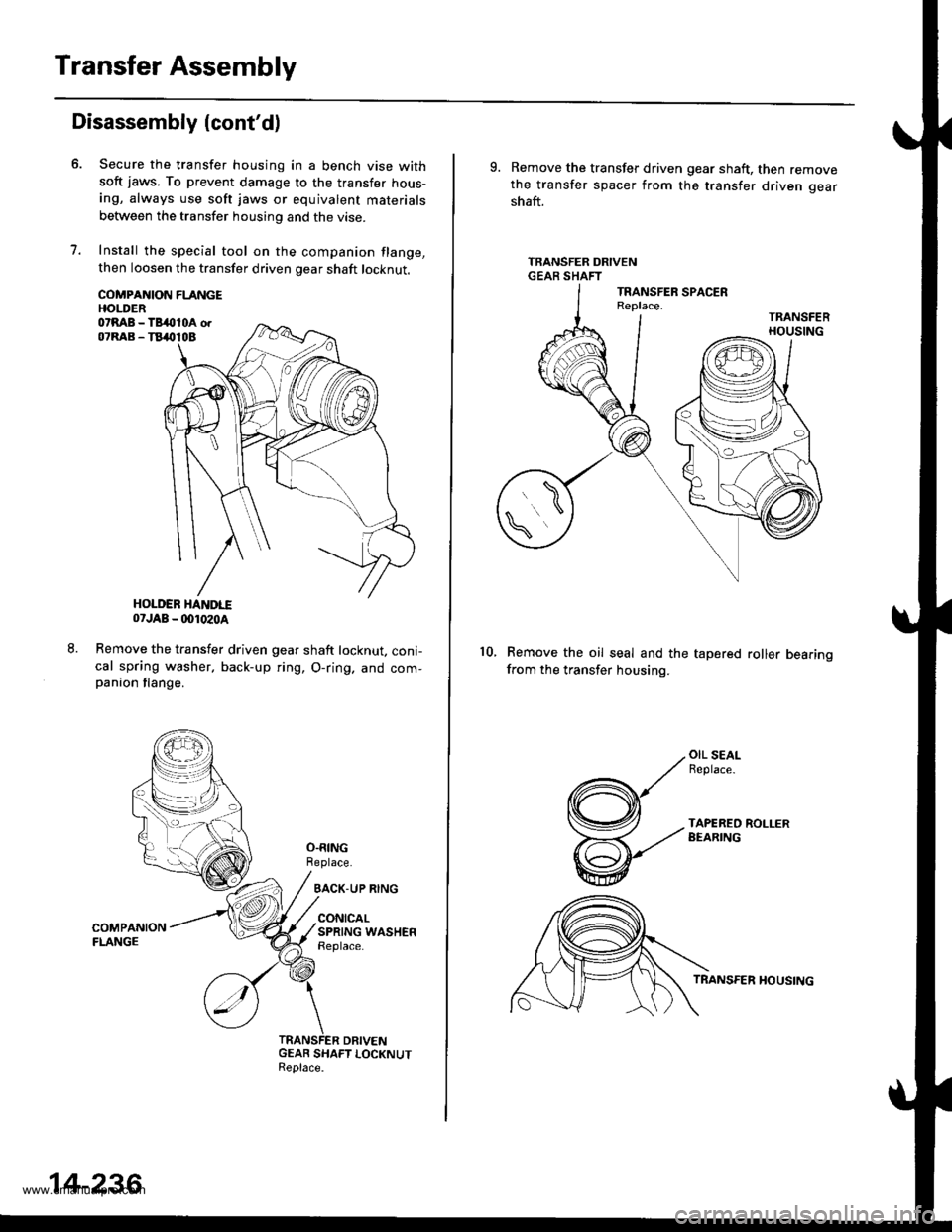
Install the special tool on the companion flange,then loosen the transfer driven gear shaft locknut.
COMPANION FLANGEHOI.DER07RAB - TB4lll0A orOTRAB - TB&TOB
HOLDER HAITDI..E07JAB _ (x)1020a
Remove the transfer driven gear shaft locknut, coni-cal spring washer, back-up ring, O-ring. and com-panion flange.
O.RINGReplace.
BACK-UP RING
CONICALSPRING WASHENReplace.
GEAR SHAFT LOCKNUTReplace.
14-236
9. Remove the transfer driven gear shaft, then removethe transfer spacer from the transfer driven gear
shaft.
TRANSFER DRIVENGEAR SHAFT
Remove the oil seal and the tapered roller bearingfrom the transfer housing.
10.
OIL SEALFeplace-
TAPEREO ROLLERBEARING
TRANSFER HOUSING
www.emanualpro.com
Page 757 of 1395
Transfer Gear Bscklash Inspection and Transfer Gear
Tooth Contact Inspection
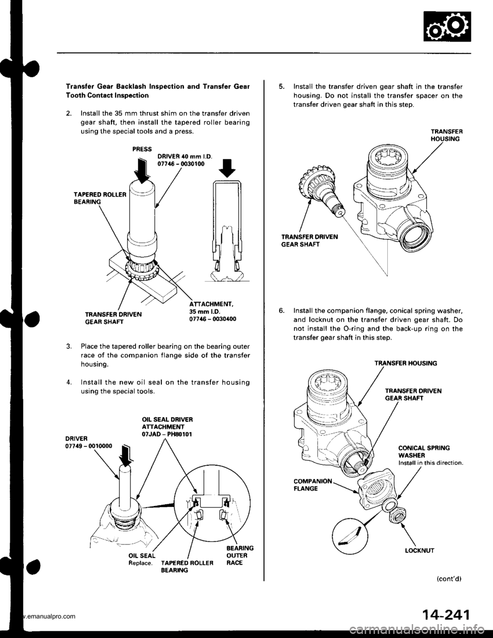
2. Install the 35 mm thrust shim on the transfer driven
gear shaft, then install the tapered roller bearing
using the special tools and a press.
DRIVER {0 mm LD.077146 - 0030100
TRANSFER DRTVEN ;;.GEAR SHAFT u, 745 - 0O304O0
Place the tapered roller bearing on the bearing outer
race of the companion flange side of the transfer
housrng.
Install the new oil seal on the transfer housing
using the special tools.
OIL SEAL DRIVERATTACHMENT07JAD - PH80101
5. Install the transfer driven gear shaft in the transfer
housing. Do not install the transfer spacer on the
transfer driven gear shaft in this step.
Install the companion flange, conical spring washer,
and locknut on the transfer driven gear shaft. Do
not install the O-ring and the back-up ring on the
transfer gear shaft in this step.
6.
COMPANIONFLANGE
{cont'd)
TRANSFER
TRANSFER HOUSING
14-241
www.emanualpro.com
Page 791 of 1395
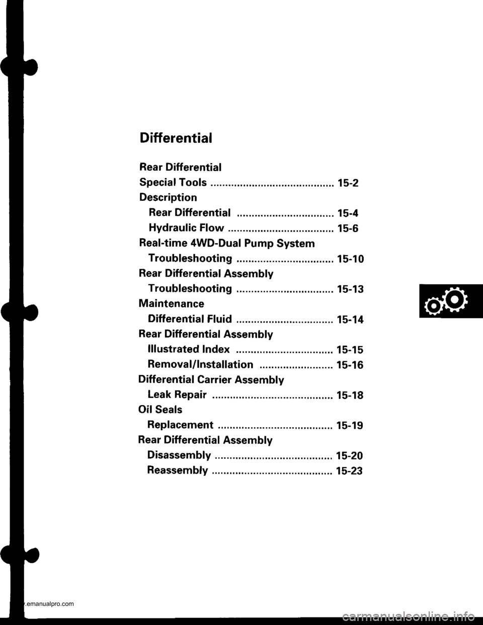
Differential
Rear Differential
Special Tools .......... ...........15-2
Description
Rear Differential ................................. 15-4
Hydraulic Flow ............ ,.. 15-6
Real-time 4WD-Dual Pump System
Troub|eshootin9 ................................. 15-10
Rear Differential Assembly
Troubleshooting ................................. 15-13
Maintenance
Differential Fluid ........... . 15-14
Rear Differential Assembly
lllustrated Index .......... .. 15-15
Removal/lnstallation .... 15-16
Differential Carrier Assembly
Leak Repair .................... 15-18
OilSeals
Replacement ...,................................... 15-19
Rear Differential Assembly
Disassembly ..........,......., 15-20
Reassembly .................... 15-23
www.emanualpro.com
Page 792 of 1395
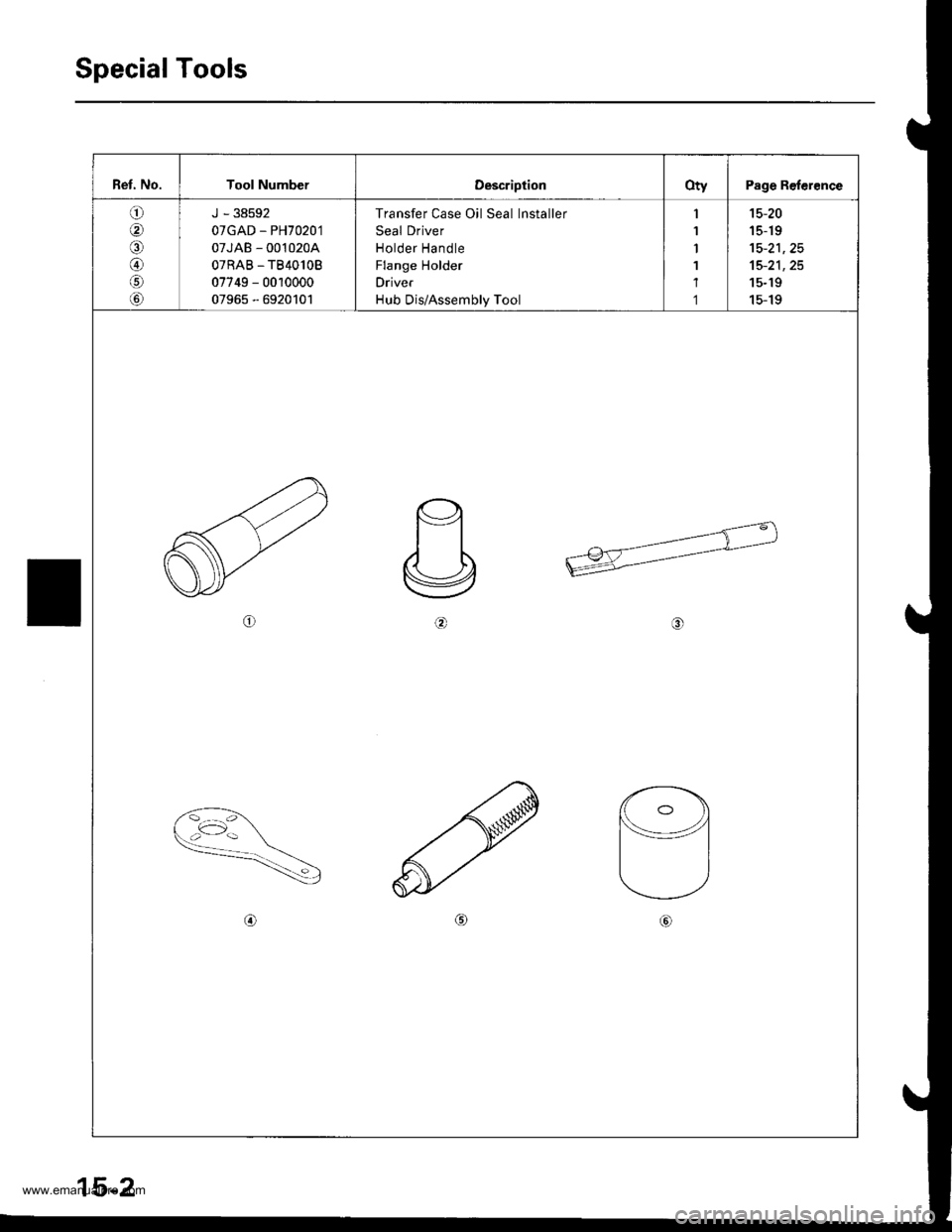
Special Tools
Ret. No.Tool NumberOescriptionotvPage Reler€nce
o
@aa
@/il
tol
J - 38592
07GAD - PH7020'1
07JAB - 0010204
OTRAB _TB40lOB
07749 - 0010000
07965 - 6920101
Transfer Case Oil Seal lnstaller
Seal Driver
Holder Handle
Flange Holder
Driver
Hub Dis/Assembly Tool
1
1
1
1
1
1
15-20
15-19
tc-zt, z9
15-21,25
15-19
15-19
6\
@
15-2
www.emanualpro.com
Page 794 of 1395

Description
Rear Differential
Outline
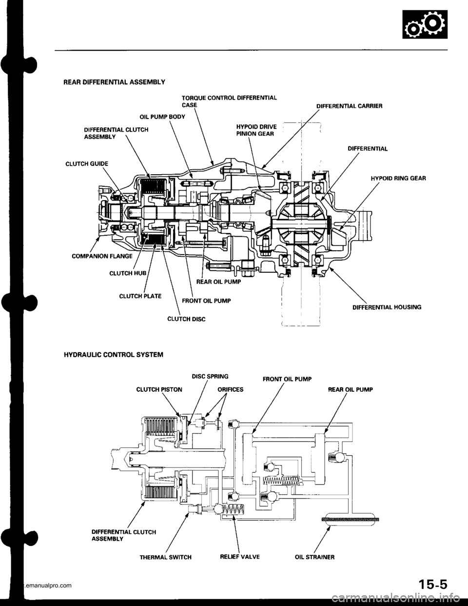
The Real-time 4WD-Dual Pump System model has a hydraulic clutch and a differential mechanism in the rear differential
assembly. Under normal conditions, the vehicle is driven by the front wheels. However, depending on to the driving force
of the front wheels and the road conditions. the system instantly transmits appropriate driving force to the rear wheels
without requiring the driver to switch between 2WD (tront wheel drive) and 4WD (four wheel drive). The switching mecha-
nism between 2WD and 4WD is integrated into the rear differential assembly to make the system light and compact.
ln addition, the dual-pump system switches off the rear-wheel-drive force when braking in a forward gear. This allows the
braking system to work properly on models equipped with an Anti-lock Braking System (ABS).
Construction
The rear differential assembly consists of the torque control differential case assembly and the rear differential carrier
assembly. The torque control differential case assembly consists of the differential clutch assembly, the companion
flange, and the oil pump body assembly. The rear differential carrier assembly consists of the differential mechanism. The
differential drive and driven gears are hypoid gears.
The oil pump body assembly consists of the front oil pump, the rear oil pump, the hydraulic control mechanism, and the
clutch piston. The clutch piston has a disc spring that constantly provides the differential clutch assembly with a preset
torque to Drevent abnormal sound.
The clutch guide in the differential clutch assembly is connected to the propeller shaft via the companion flange, and it
receives the driving force lrom the transfer assembly. The clutch guide rotates the clutch plate and the front oil pump in
the oil pump body.
The clutch hub in the differential clutch assembly has a clutch disc that is splined with the hypoid drive pinion gear. The
hypoid drive gear drives the rear oil pump.
The front and rear oil pumps are trochoidal pumps. The rear oil pump capacity is 2.5 percent larger that the front oil pump
to handle the rotation difference between the front and rear wheels caused by worn front tires and tight corner braking.
The oil pumps are designed so the fluid intake works as a fluid discharge when the oil pumps rotate in reverse. Genuine
Honda CVT fluid is used instead of differential fluid.
Operation
When there is a difference in rotation speed between the front wheels (clutch guide) and rear wheels (hypoid driven gear),
hydraulic pressure from the front and rear oil pumps engages the differential clutch, and drive force from the transler
assembly is applied to the rear wheels.
The hydraulic pressure control mechanism in the oil pump body selects 4WD mode when the vehicle is started abruptly,
or when accelerating in a forward or reverse gear (causing rotation difference between the front and rear wheels). or
when braking in reverse gear {when decelerating). lt switches to 2WD mode when the vehicle is driven at a constant speed
in forwar! or reverse gear (when there is no rotation difference between the front and rear wheels), or when braking in a
fo rwa rd gear (when decelerating).
To protect the system, the differential clutch assembly is lubricated by hydraulic pressure generated by the oil pumps in
both 4WD and 2WD modes. Also, the thermal switch relieves the hydraulic pressure on the clutch piston and cancels 4WD
mode if the temDerature of the differential fluid rises above normal.
www.emanualpro.com
Page 795 of 1395
TOROUE CONTROL OIFFERENTIAL
REAR DIFFERENTIAL ASSEMBLY
OIL PUMP BODY
OIFFERENTIAL CLUTCHHYPOID DRIVEPINION GEAR
OIFFERENTIAL CARRIER
DIFFERENTIAL
HYPOID RING GEAR
DIFFERENTIAI- HOUSING
REAR OII- PUMP
ASSEMBLY
CLUTCH GUIDE
COMPANION FLANG€
CLUTCH HUB
CLUTCH PLATE
HYDRAULIC CONTROL SYSTEM
CLUTCH PISTON
CLUTCH DISC
REAR OIL PUMP
FRONT OIL PUMP
DISC SPRINGFRONT OIL PUMP
DIFFEREMT|AL CLUTCHASSEMBI-Y
THERMAL SWITCHRELIEF VALVEOIL STRAINER
15-5
www.emanualpro.com
Page 796 of 1395
Description
Hydraulic Flow
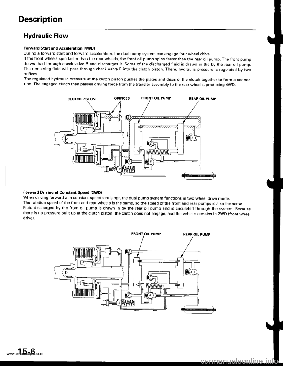
Forward Start and Acceleration l4WD)During a forward start and forward acceleration, the dual pump system can engage four wheel drive.lf the front wheels spin faster than the rear wheels, the front oil pump spins faster than the rear oil pump. The front pump
draws fluid through check valve B and discharges it. Some of the discharged fluid is drawn in the by the rear oil pump.The remaining fluid will pass through check valve E into the clutch piston. There, hydraulic pressure is regulated by twoorifices.
The regulated hydraulic pressure at the clutch piston pushes the plates and discs of the clutch together to form a connec-tion. The engaged clutch then passes driving force from the transfer assembly to the rear wheels, producing 4WD.
oRrFtcEsFRONT OIL PUMPREAR OIL PUMP
Forward Driving at Constant Speed lzWD)When driving forward at a constant speed (cruising), the dual pump system functions in two wheel drive mode.The rotation speed of the front and rear wheels is the same, so the speed of the front and rear pumps is also the same.Fluid discharged by the front oil pump is drawn in by the rear oil pump and is circulated through the system. Becausethere is no pressure built up at the clutch piston, the clutch does not engage, and the vehicle remains in 2WD (front wheeldrive).
FRONT OIL PUMP
15-6
www.emanualpro.com
Page 797 of 1395
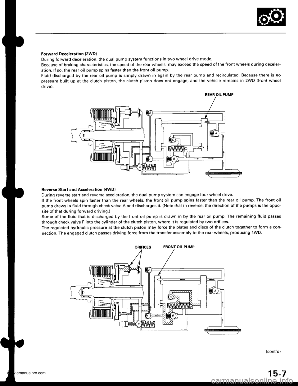
Forward Deceleration l2WDl
During forward deceleration, the dual pump system functions in two wheel drive mode.
Because of braking characteristics, the speed of the rear wheels may exceed the speed ol the front wheels during deceler-
ation. lf so, the rear oil pump spins faster than the front oil pump.
Fluid discharged by the rear oil pump is simply drawn in again by the rear pump and recirculated. Because there is no
pressure built up at the clutch piston. the clutch piston does not engage, and the vehicle remains in 2WD (front wheel
drive).
Reverse Start and Acceleration (4WD)
During reverse start and reverse acceleration, the dual pump system can engage four wheel drive.
lf the front wheels spin faster than the rear wheels, the front oil pump spins faster than the rear oil pump. The front oil
pump draws in fluid through check valve A and discharges it. {Note that in reverse, the direction of the pumps is the oppo-
site of that during forward driving.)
Some of the fluid that is discharged by the front oil pump is drawn in by the rear oil pump. The remaining fluid passes
through check valve F into the cylinder of the clutch piston, where it is regulated by two orifices.
The regulated hydraulic pressure at the clutch piston may force the plates and discs of the clutch together to form a con-
nectlon. The engaged clutch passes driving force from the transfer assembly to the rear wheels, producing 4WD.
oRtFtcEsFRONT OIL PUMP
{cont'd)
15-7
REAR OIL PUMP
www.emanualpro.com
Page 798 of 1395
Description
Hydraulic Flow (cont'dl
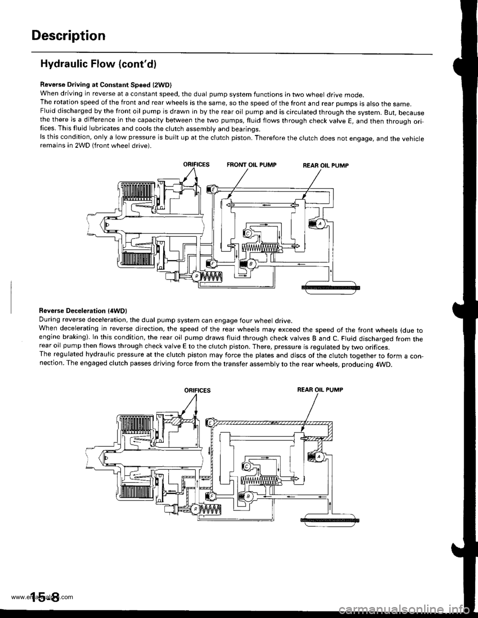
Reverse Driving at Constant Speed l2WD)when driving in reverse at a constant speed, the dual pump system functions in two wheel drive mode.The rotation speed of the front and rear wheels is the same, so the speed of the front and rear pumps is also the same,Fluid discharged by the front oil pump is drawn in by the rear oil pump and is circulated through the system. But, becausethe there is a difference in the capacity between the two pumps, fluid flows through check valve E, and then through ori-Iices. This fluid lubricates and cools the clutch assembly and bearings.ls this condition, only a low pressure is built up at the clutch piston. Therefore the clutch does not engage, and the vehicleremains in 2WD (front wheel drive).
Reverse Deceleration l/tWDl
During reverse deceleration, the dual pump system can engage four wheel drive.When decelerating in reverse direction, the speed of the rear wheels may exceed the speed of the front wheels (due toengine braking). In this condition, the rear oil pump draws fluid through check valves B and C. Fluid discharged from therear oil pump then flows through check valve E to the clutch piston. There, pressure is regulated by two orifices.The regulated hydraulic pressure at the clutch piston may force the plates and discs of the clutch together to form a con,nection. The engaged clutch passes driving force from the transfer assembly to the rear wheels, producing 4WD.
oRtFtcEsREAR OIL PUMP
www.emanualpro.com
Page 803 of 1395
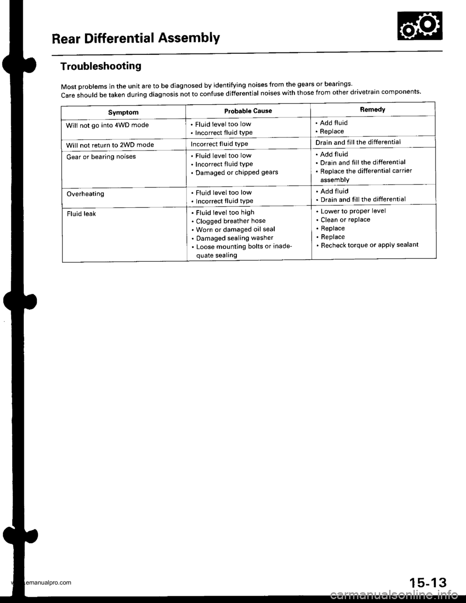
Rear Differential AssemblY
Troubleshooting
Most problems in the unit are to be diagnosed by identifying noises from the gears or bear'ngs'
care should be taken during diagnosis not to confuse differential noises with those from other drivetra'n components'
SymptomProbable CauseRemedy
Will not go into 4WD mode. Fluid level too low
. Incorrect fluid type
. Add fluid. Replace
Will not return to 2WD modeIncorrect fluid typeDrain and fill the differential
Gear or bearing noisesFluid level too low
Incorrect fluid type
Damaged or chipped gears
Add fluid
Drain and fill the differential
Replace the differential carrier
assemory
Overheating. Fluid leveltoo low
. Incorrect fluid type
. Add fluid. Drain and fill the differential
Fluid leakFluid level too high
Clogged breather hose
Worn or damaged oil seal
Damaged sealing washer
Loose mounting bolts or inade-
quate sealing
Lower to proper level
Clean or replace
Replace
Replace
Recheck torque or aPPIY sealant
15-13
www.emanualpro.com