Rear HONDA CR-V 1998 RD1-RD3 / 1.G Workshop Manual
[x] Cancel search | Manufacturer: HONDA, Model Year: 1998, Model line: CR-V, Model: HONDA CR-V 1998 RD1-RD3 / 1.GPages: 1395, PDF Size: 35.62 MB
Page 1207 of 1395

BLKG401
GroundWir€ ColorComponent or Circuits Grounded
ABS indicator circuit
ABS control unit
Ashtray light
A/T gear position indicator dimming circuit
Brake fluid level switch
Clock ('98 - 00 models)
Clutch inrerlock switch (M/T)
Clutch switch (Mff)
Cruise main switch
Cruise indicator circuit
Cruise control unit
Dash lights brightness controller
Data iink connector
Daytime running rights control unit (Canada)
Front accessary socket
Gauge and indicators
Heater control panel
lgnition key light control unit ('97 model)
lgnition key switch
Integrated control unit
Interlock control unit (Ay'T)
Parking pin switch {A,/T)
Power window relay
Rear accessary socket relay
Bear window defogger relay
Rear window wiper control unit ('97 model)
Service check connector
Spotlights
SRS indicator circuit
Turn signal/hazard relay
Windshield wiper motor
Windshield wiper/washer switch- plus everything grounded through G402
ABS control unit
Blower motor relay
Blower motor high relay
ELD unit (USA)
Power transistor- plus everything grounded through G401
BLKG402
{cont'd)
23-47
www.emanualpro.com
Page 1208 of 1395
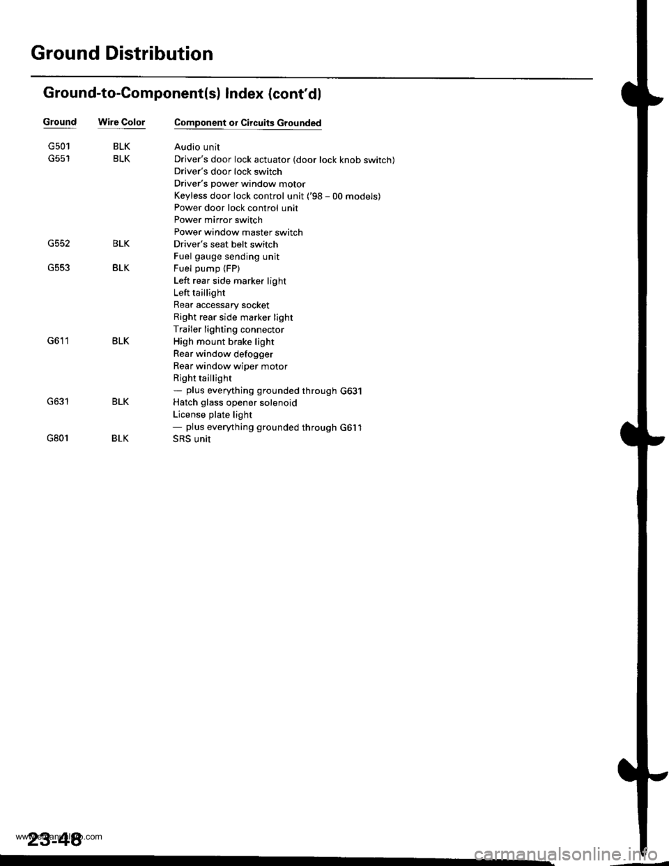
Ground Distribution
Ground-to-Component(sl Index (cont'dl
Wire ColorGround
G552
G501
G801
BLK
BLK
BLK
BLK
Component or Circuits Grounded
Audio unit
Driver's door lock actuator (door lock knob switch)
Driver's door lock switch
Driver's power window motor
Keyless door lock control unit ('98 - 00 models)
Power door lock control unit
Power mirror switch
Power window master switch
Driver's seat belt switch
Fuel gauge sending unit
Fuel pump (FP)
Left rear side marker light
Left taillight
Rear accessary socket
Right rear side marker light
Trailer lighting connector
High mount brake light
Rear window defogger
Rear window wiper motor
Rjght taillight- plus eveMhing grounded through G631
Hatch glass opener solenoid
License plate light- plus eveMhing grounded through G6l1
SRS unit
BLK
BLK
BLK
23-48�
www.emanualpro.com
Page 1212 of 1395
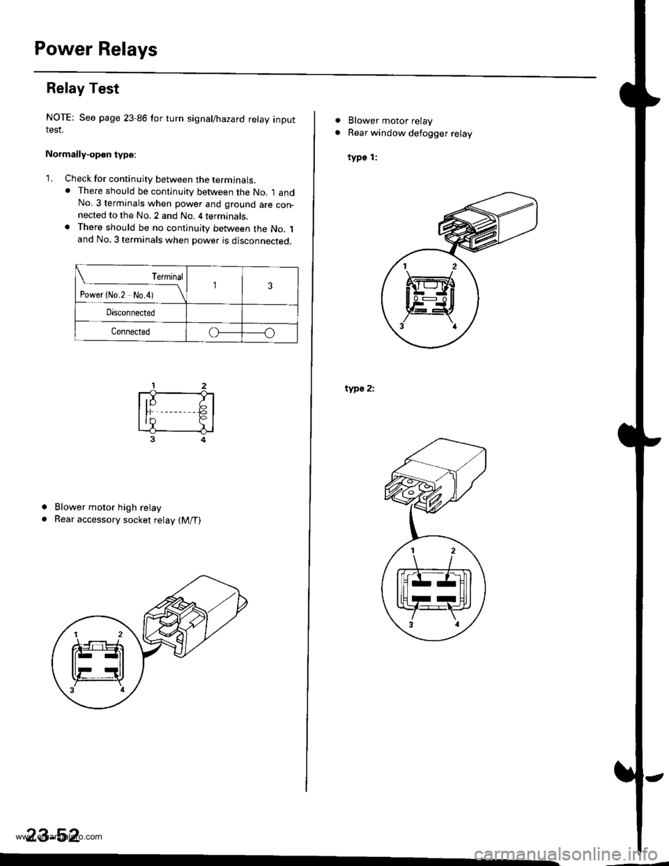
Power Relays
Relay Test
NOTE: See page 23-86 for turn signal/hazard relay inputIESI.
Normally-opon type:
'1. Check for continuity between the terminats.. There should be continuity between the No. I andNo. 3 terminals when power and ground are con-nected to the No. 2 and No. 4 terminals.. There should be no continuity between the No. 1and No. 3 terminals when power is disconnected.
Terminal
t"""r f *r t*i__\l3
Disconnected
Connectedo
a
a
Blower motor high relay
Rear accessory socket relay (M/T)
23-52
ffi
. Blower motor relay
. Rear window defogger relay
type 1:
type 2i
H
al 2 \
Itrrz-Hl
llHrrUll
Y:F,',3 al
www.emanualpro.com
Page 1213 of 1395
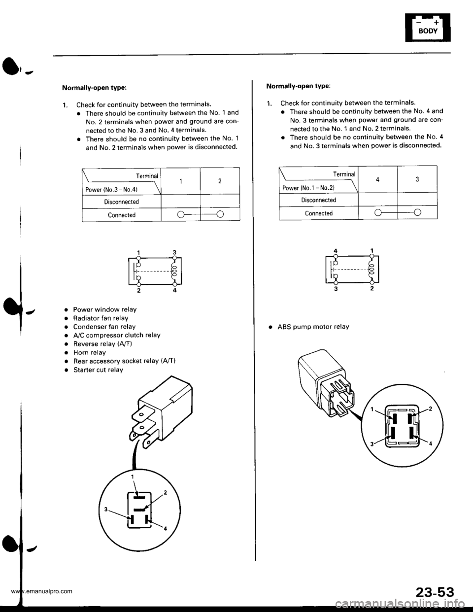
Normally-open type:
1. Check for continuity between the terminals.
. There should be continuity between the No. 1 and
No. 2 terminals when power and ground are con
nected to the No. 3 and No. 4 terminals
. There should be no continuitv between the No. 1
and No. 2 terminals when power is disconnected.
Terminal
t.*", ^"- t*f \
12
Drsconnected
Connectedoo
a
a
a
a
a
a
Power window relay
Radiator fan relay
Condenser fan relay
A,/C compressor clutch relay
Reverse relay (A/f)
Horn relay
Rear accessory socket relay {A,/T)
Starter cut relay
\K,
Normally-open type:
1. Check for continuity between the terminals.
. There should be continuity between the No. 4 and
No.3 terminals when power and ground are con-
nected to the No. 1 and No. 2 terminals.
. There should be no continuity between the No. 4
and No. 3 terminals when power is disconnected.
Terminal
tl**^-*
-_\3
Disconnected
Connectedo----o
. ABS pump motor relay
www.emanualpro.com
Page 1220 of 1395
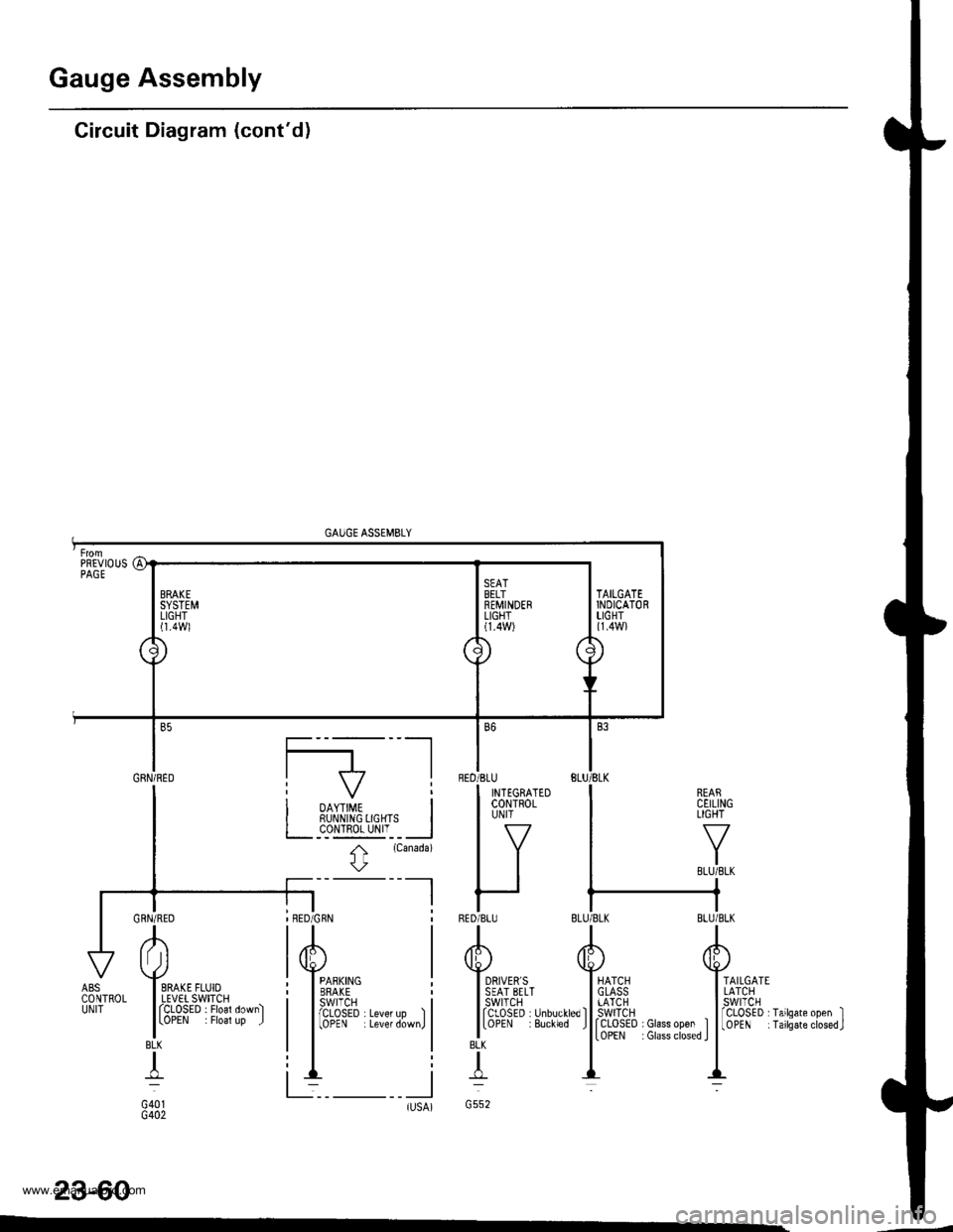
Gauge Assembly
Circuit Diagram (cont'd)
GAUGE ASSEMBLY
REARCEILINGLIGHT
TAILGATELATCHswtTcH
rCLOSED I Glass open ItoPEN : Glass closed I
fCLoSED rTailsate open II0PEN iTailsateclosed.J
23-60
BLK
T
G552tlsA)-
AI Jl
I SRAKE FLUIOI LEVET SWITCHI fCLOSED . Floal down)
lLoPEN . Floal up J
BLK
+
G401G402
ABSCONTROLUNIT
PREVIOUSPAGE
a1
\J
BRAKESYSTEMLIGHTl1.4Wl
\
./
SEATBELTREMINDERLIGHT(1.4W)
\/'
7\
\
TAILGATEINDICATORLIGHT{1.4W}
Gnru;neo I f7 |
I i oo,,#, i| | RUI\N|NG 0GHTS I
I L__c_o!l!g_yI'__l
I t
rcanada)
l\
-l I
BED
RED
B6
'BLU
I INTEGRATEDI coNTRoLI UN|T
lv
IItt
r-IBLU
www.emanualpro.com
Page 1223 of 1395
o-.
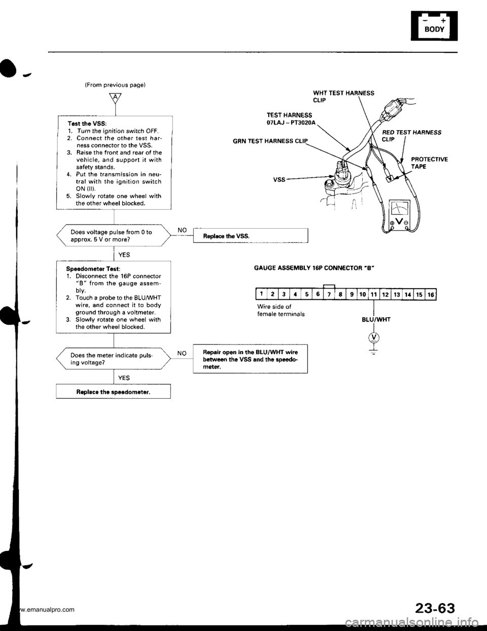
WHT TEST HARNESSCLIP
TEST HARNESSOTLAJ _ PT3O2OA
GRN TEST HARNESS
BED TEST HARNESSct-tP
PROTECTIVETAPE
(From previous page)
T6st the VSS:1. Turn the ignition switch OFF.2, Connect the other test har-ness connector to the VSS,3. Raise the front and rear of thevehicle, and support jt withsafety stands.4. Put the transmission in neu-tral with the ignition switchoN r).5. Slowly rotate one wheel withthe other wheel blocked.
Does voltage pulse from 0 toapprox, 5 V or more?
Spoodom6tor T6st:1, Disconnect the 16P connector"B" from the gauge assem
2. Touch a probe to the BLUMHTwire. and connect it to bodyground through a voltmeter.3. Slowly rotate one wheel withthe other wheel blocked.
R.p.ir opon in the BLU/WHT wirebetwe€n the VSS and the 3oeedo-mgter.
Does the meter indicate puls-ing voltage?
GAUGE ASSEMBLY 16P CONNECTOR 'B-
Wire side offemale termin6lsBLU/WHT
I(v)
It
23-63
www.emanualpro.com
Page 1241 of 1395
Adjustment
Bstore adiusting the headlights:
. Park the vehicle on level ground
. Make sure the fuel tank is tull
. The driver or someone who weighs the same should
sit in the driver's seat.
. Load the trunk with the items you usually carry'
. Push down on the front and rear bumpers several
times to make sure the vehicle is sitting normally'
CAUTION: Halogen headlights become very hot in use;
do not touch them or the atiaching hardware immedi-
ately after they have been turned off.
1. ODen the hood.
2. Remove the left inner fender {see section 20).
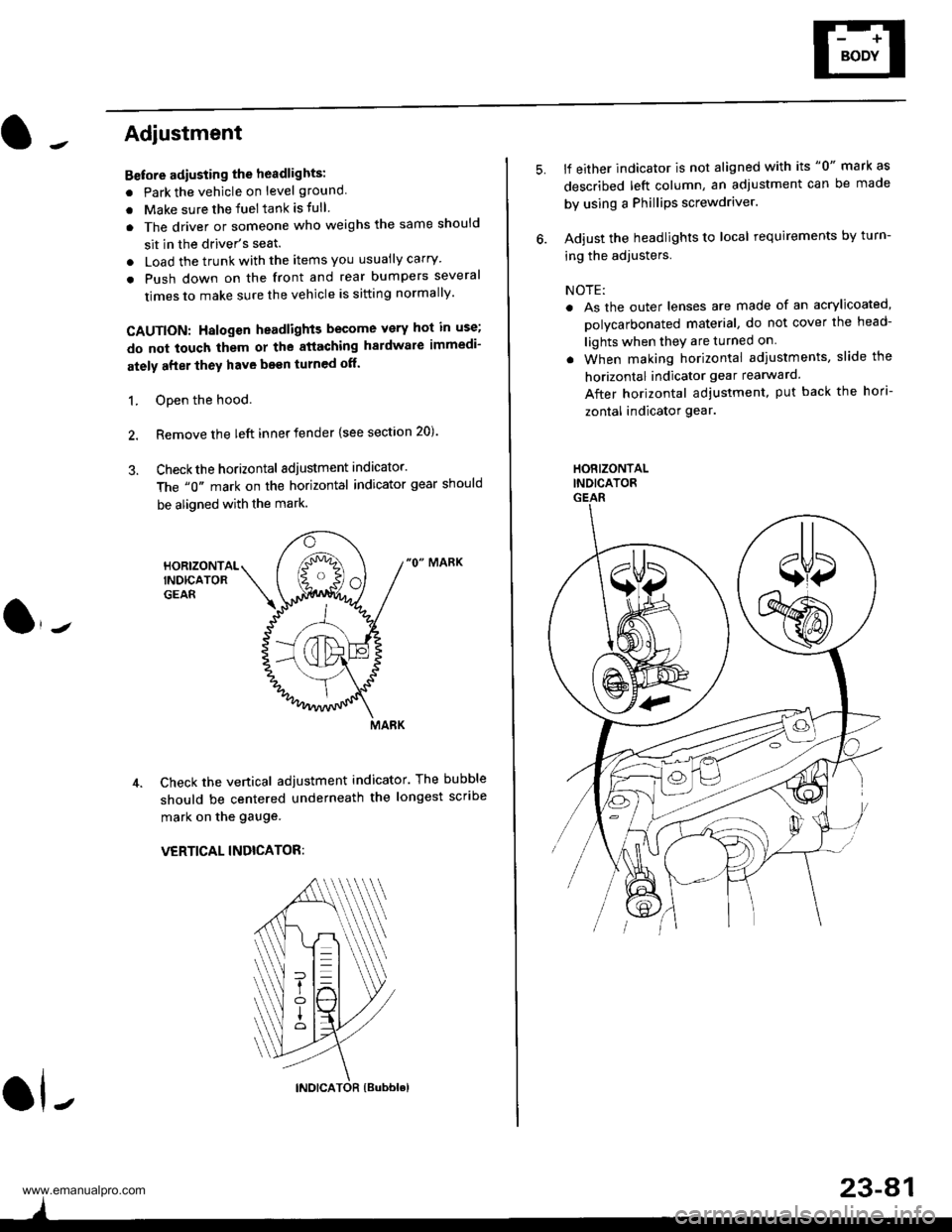
3. Checkthe horizontal adjustment indicator.
The "0" mark on the horizontal indicator gear should
be aligned with the mark.
"0" MARK
Check the vertical adjustment indicator. The bubble
should be centered underneath the longest scribe
mark on the gauge.
VERTICAL INDICATOR:
ol-
)
5.lf either indicator is not aligned with its "0" mark as
described left column, an adjustment can be made
by using a Phillips screwdriver.
Adjust the headlights to local requirements by turn-
ing the adjusters.
NOTE:
. As the outer lenses are made of an acrylicoated,
polycarbonated material, do not cover the head-
lights when they are turned on
. When making horizontal adiustments, slide the
horizontal indicator gear rearward.
After horizontal adjustment, put back the hori-
zontal indicator gear.
HORIZONTALINDICATORGEAR
23-A1
www.emanualpro.com
Page 1242 of 1395
Rear Side Marker Lights/
License Plate LightTaillights
Replacement
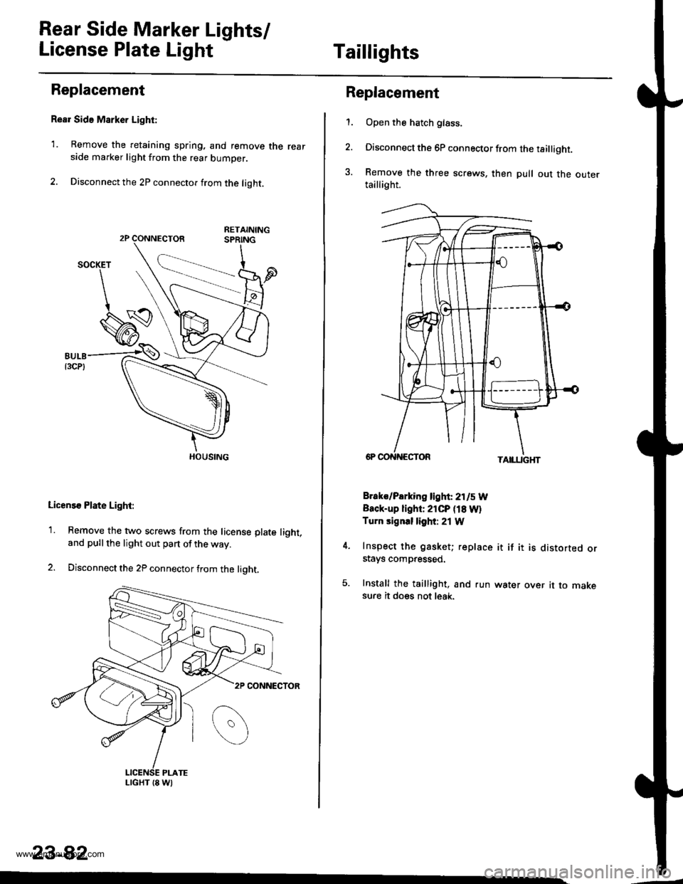
Rear Side Marke. Light:
1. Remove the retaining spring, and remove the rearside marker light from the rear bumper.
2. Disconnect the 2P connector from the light.
RETAINING
HOUSING
Licens€ Plate Light:
1. Remove the two screws from the license plate light,and pull the light out part of the way.
2. Disconnect the 2P connector from the light,
23-A2
LIGHT (8 WI
Replacement
1. Open the hatch glass.
2. Disconnect the 6P connector from the taillight.
3. Remove the three screws, then pull out the outertaillight.
Brak€/Plrking light 2115 W
Back-up light: 21CP (18 W)
Turn signll light 21 W
Inspect the gasket; replace it if it is distorted or$ays compressed.
Install the taillight, and run water over it to makesure it does not leak.
www.emanualpro.com
Page 1252 of 1395
Interior Lights
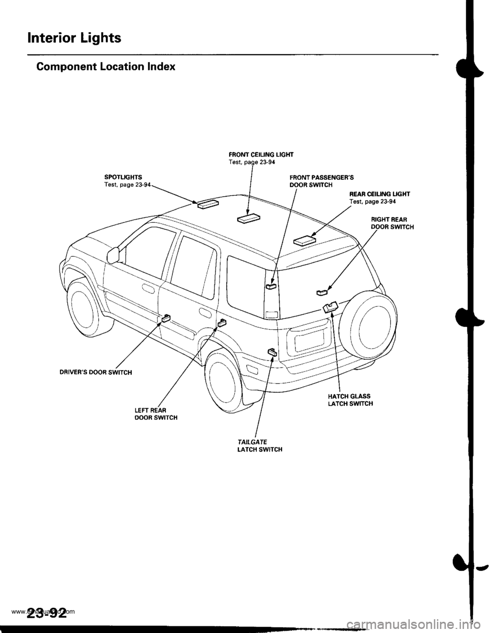
Component Location Index
SPOTLIGHTSTest, page
DRIVER'S DOOR SWITCH
LEFT REARoooR swtTcH
FRONT CEILING LIGHTTest, page 23-94
FRONT PASSENGER'SDOOR SWITCH
REAR CCILING LIGI{TTest, page 23-94
RIGHT REARswtTcH
HATCH GLASSLATCH SWITCH
TAILGATELATCH SwlTCH
23-92
www.emanualpro.com
Page 1257 of 1395
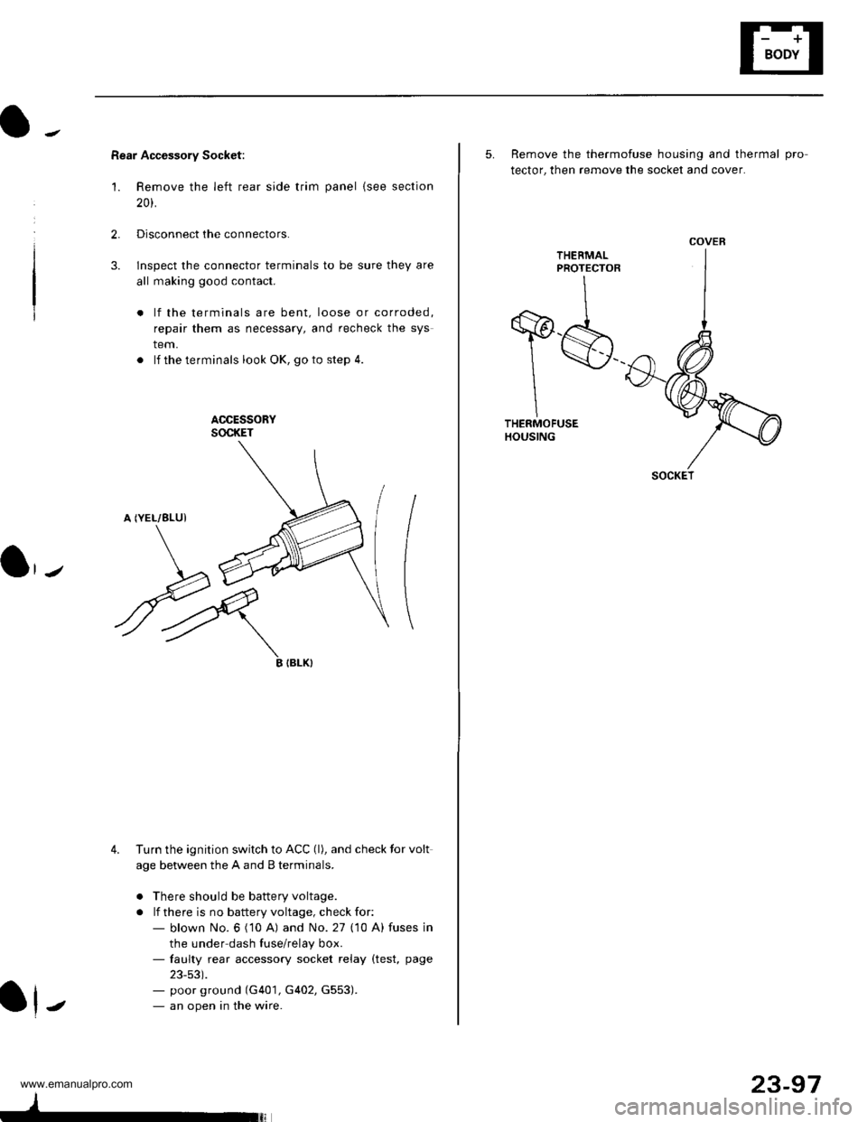
Rear Accessory Socket:
'1. Remove the left rear side trim panel {see section
20t.
2.Disconnect the connectors.
lnspect the connector terminals to be sure they are
all making good contact.
lf the terminals are bent, loose or corroded,
repair them as necessary, and recheck the sys
tem.
. lf theterminals look OK, goto step 4.
ACCESSORYSOCKET
A (YEL/8LUI
3.
\J
ryIIBLK}
4. Turn the ignition switch to ACC (l), and check tor volt
age between the A and B terminals.
o There should be battery voltage.
. lf there is no battery voltage, check for:- blown No. 6 ('10 A) and No. 27 (10 A) fuses in
the under dash fuse/relay box.- faulty rear accessory socket relay (test, page
23-53).- poor ground (G401, G402, G553).- an open in the wire.J
23-97
5. Remove the thermofuse housing and thermal pro
tector, then remove the socket and cover.
THEEMALPROTECTOR
T$THERMOFUSEHOUSING
COVER
SOCKET
www.emanualpro.com