1-1 HONDA CR-V 1998 RD1-RD3 / 1.G User Guide
[x] Cancel search | Manufacturer: HONDA, Model Year: 1998, Model line: CR-V, Model: HONDA CR-V 1998 RD1-RD3 / 1.GPages: 1395, PDF Size: 35.62 MB
Page 21 of 1395
Lift and Support Points
Lift and Safety Stands
ffi When heaw rear components such as suspension, Iuel tank, spare tire and tailgate are to b€ lemoved, place
!iiii-'rn"t r""igtrt in the trunk before hoisting. When substantial weight is removed flom the lear ot the vehicle, the
center of gravity may change and can cause the vehicle to tip fotward on the hoist'
NOTE: Since each tire/wheel assembly weighs approximately 30 lbs (14 kg), placing the front wheels in the cargo area can
assist with weight distribution.
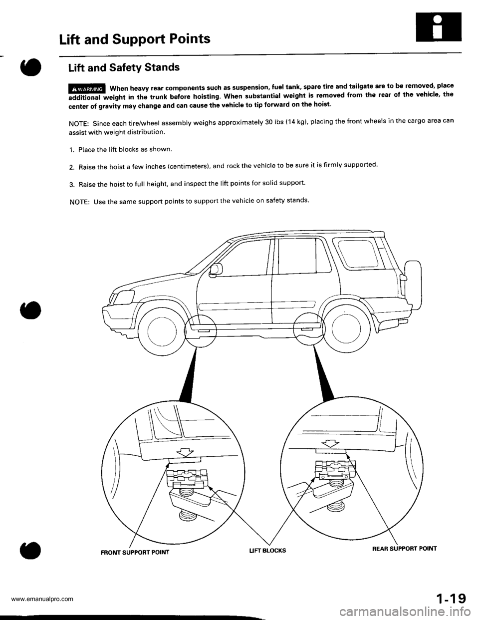
1. Place the lift blocks as shown.
2. Raise the hoist a few inches (centimeters), and rock the vehicle to be sure it is firmly supported.
3. Raise the hoist to full height, and inspect the lift points for solid support'
NOTE: Use the same suppon points to support the vehicle on safety stands'
LIFT BLOCKSREAR SUPPORT POIMTFRONT SUPPORT POINT
1-19
www.emanualpro.com
Page 148 of 1395
Special Toolstl
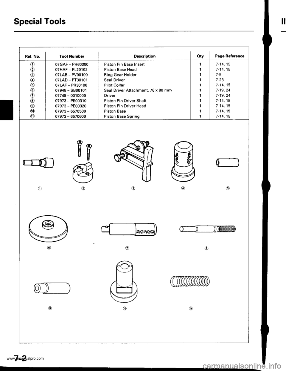
Ref, No. I Tool NumborDescriptionOty Page Reterence
o
@
@/6
@
o
@
@
@
@
07GAF - PH60300
07HAF - P120102
07LAB - PV00100
07LAD - PT30101
07LAF - PR30100
07948 - S800101
07749 - 0010000
07973 - PE00310
07973 - PE00320
07973 - 6570500
07973 - 6570600
Piston Pin Base lnsert
Piston Base Head
Ring Gear Holder
Seal Driver
Pilot Collar
Seal Driver Attachment. 76 x 80 mm
Driver
Piston Pin Driver Shaft
Piston Pin Driver Head
Piston Base
Piston Base Spring
,l
1
I
I
1
1
1
1
1
1
1
7-14,15
1-'t4,15
1-5
1-23
7-14,15
7-'t9,24
7 -'t9, 24
1-14,15
7-14,15
7-'t4,15
7-14,15
eEEg
o
a@
0
o@
7-2
www.emanualpro.com
Page 204 of 1395

Fuel and Emissions
Special Tools ...................... 11-2
Component Locations
lndex ...................... ....,.... 11-3
Svstem Description
Vacuum Connections ...........,....,.,................. 1 1-9
Electrical Connections ................................... 1 1-15
System Connectors .,.,,.,............................,.,. 1 1-36
Troubleshooting
Troubleshooting Procedures,.,..................... 11-60
Engine Control Module/Powertrain ConttolModule Terminal Arrangement .............., 11-67
Diagnostic Trouble Code Chart .................... 1 t-75
How to Read Flowcharts .......,.....,.,............... I 1-79
PGM-Fl System
System Description .................,.,.,,,............... 1 1-80
Troubleshooting Flowcharts
Engine Control Module/PowertrainControl Module ........11-52
Manifold Absolute Pressure Sensor ............. 11-90
Intake Air Temperature Sensor .................... 1 1-95
Engine Coolant Temperature Sensor .,..,.,.... 1 1-99
Throttle Position Sensor ...........,.....,.,.,..,...... I 1'103
Primary Heated Orygen Sensor (Sensor 1) ... 11-110
Secondary Heated Oxygen Sensor{Sensor 2l .................. 1 1-117
Heated Oxygen Sensor Heater ..................... 11-121
Fuef Supply System ......11-124
Random Misfire ,....,.,..... 11-126
Mistire Detected in One Cylinder .....-........... 11-128
Knock Sensor ................ 11-130
CKP/TDC/CYP Sensor .................................... 1 1-131
Vehicle Speed Sensor ...............................,.... 1 1-135
Barometric Pressure Sensor .....,...,...,.,,........ 1 1-137
Electrical Load Detector ...,.,.......................... 1 1-138
CKF Sensor ................,.,, '11-112
ECM/PCM lnternaf Circuit ............................. 11'117
HO2S Replacement .,.,.,. 11-148
ldle Control System
System Description ............ 11-149
Troubleshooting Flowcharts
ldle Control System ...... 11-150
fdle Air Control Valve ......................,............. 11-152
Air Conditioning Signal ................................. I 1-155
Alternator FR Signal ...................................... 1 1-159
Starter Switch Si9na1 .................................... t l-161
Power Steering Pressure Switch Signal ...... 11-162
Brake Switch Si9na1 ...................................... 11-166
Fast ldle Thermo Valve .,.,.............................,.,.,. 11-168
ldle speed setting .............. 11-169
Fuel Supply System
Fuel Lines ............................ 11-171
Fuef Tube/Ouick-Conneci Fittings ..................... 11 -175
System Description ............ 11-178
Fuel Pressurg ...................... 11-178
Fuel Iniectors ................,..... 11-179
Fuel Pressure Re9u1ator .............................,.,...., f 1-181
Fuef Fifter ....,.,.,.,,,,.,............11-142
Fuel Pump ........................... 11-183
Fuel Gauge .......................... 11-184
Fuel Gauge Sending Unit ................................... I 1-185
Low Fuel Indicator System ...........,.,..,............... 1 1-185
PGM-FI Main Relay ............. 11-187
Fue|Tank................ ............. 11-191
Intake Air System
System Description ............ 11-193
Air Cleanel ,.,.,..................... 11-194
Throttle Cable ..................... 11-194
Throttle Body........ .............. 11-196
Emission Control System
System D$cription ...,....,.,. 11-199
Tailpipe Emission ............... 11-199
Three Way Catalytic Converter ..................,.,...,, 11-199
Positive Crankcase Ventilation System .,.,,,,.,.., 11-2O1
Evaporative Emission Controls .........,.,.,............ 11-203
www.emanualpro.com
Page 205 of 1395
Special Tools
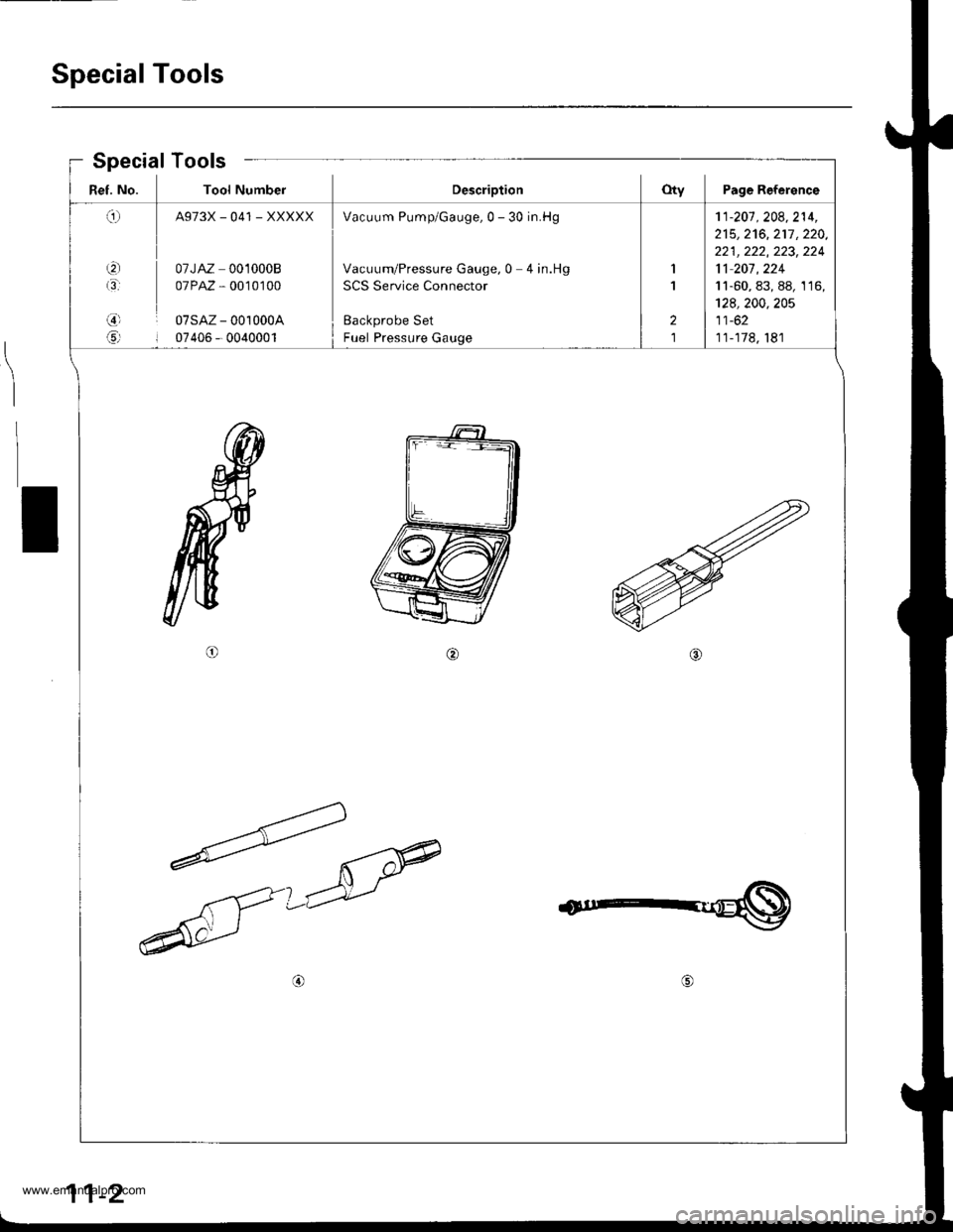
Ref. No. Tool NumberDescriptionOty Page Reference
q
t3'
,3)l
6rl
A973X_041 _XXXXX
07JAZ 0010008
07PAZ , 0010100
07sAz - 001000A
07405 - 0040001
Vacuum Pump/Gauge,0 - 30 in.Hg
Vacuum/Pressure Gauge, 0 4 in.Hg
SCS Service Connector
Backprobe Set
Fuel Pressure Gauge
1
1
2
1
'11-201 . 208,214,
215,2't6,217 ,220,
221 , 222, 223, 224
11 207 , 224
11-60, 83, 88, 1 16,
128,200,205
11-62
11-178, 181
Special Tools
I
11-2
www.emanualpro.com
Page 206 of 1395
Component Locations
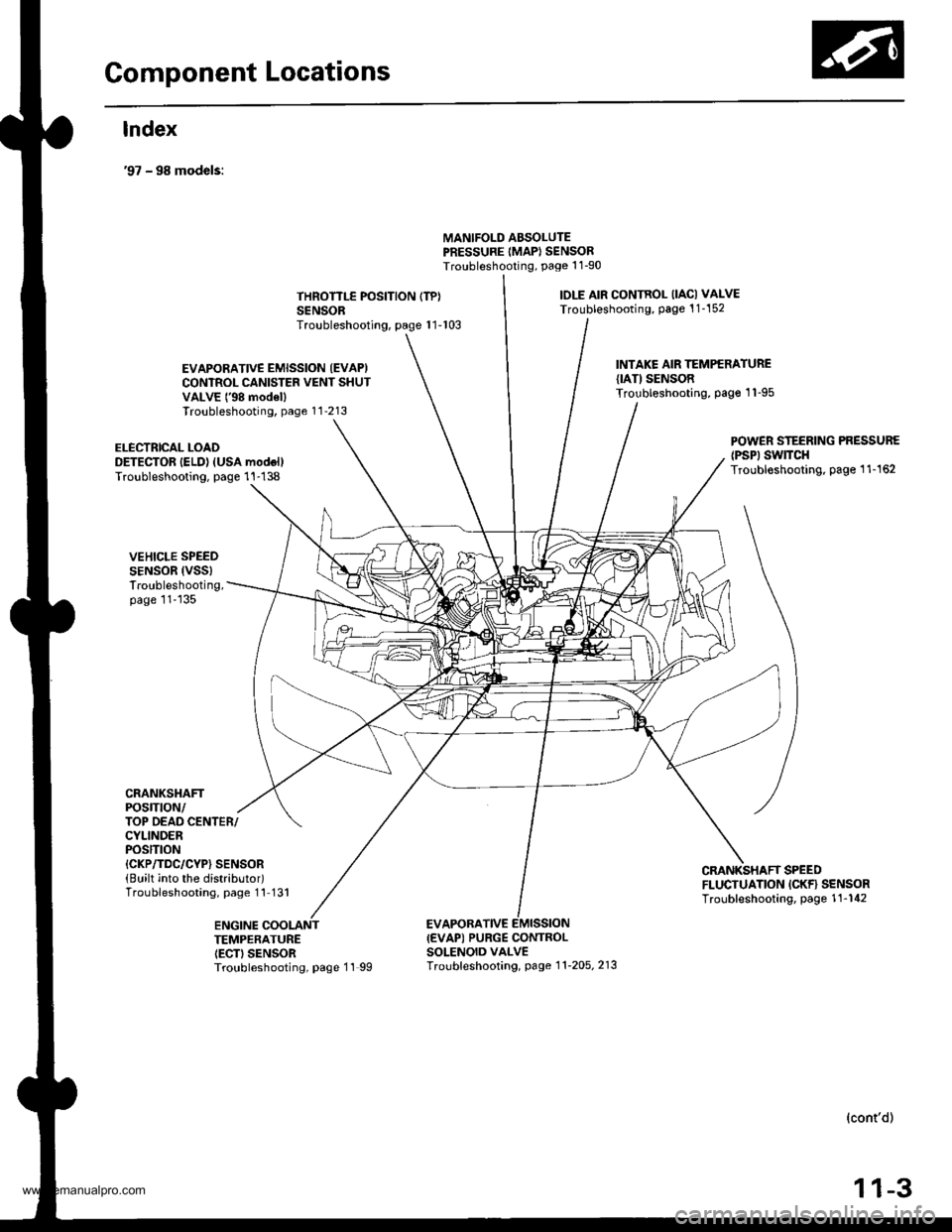
lndex
'97 - 98 models:
MANIFOLD ABSOLUTEPRESSURE IMAP} SENSORTroubleshooting, Page 1 1-90
THROTTLE POSITION (TP}
SENSORTroubleshooting, page 1 1-103
toLE AtR CONTROL llAcl VAI-VE
Troubleshooting, page 1 1-152
EVAPORATIVE EMISSION (EVAP)
CONTROL CANISTER VENT SHUTVALVE t'98 mod€llTroubleshooting, page 11'213
INTAKE AIR TEMPERATUREIIATI SENSORTroubleshooting. page 1 'l -95
ELECTRICAL LOADDETECTOR IELD) (USA modol)Troubleshooting, page 1 1-138
VEHICLE SPEEDSENSOR (VSS)
Troubleshooting,page 11'135
CRANKSHAFTPOSTTtON/
POWER STEERING PRESSURElPsPl swtrcHTroubloshooting, page 1 1-162
TOP OEAD CENTER/CYLINDERPOStTtON{CKP/TDC/CYP} SENSOR(Built into the distributor)Troubleshooting, page 1 l-131
CMNKSHAFT SPEEDFLUCTUATION ICKF} SENSORTroubleshooting. page 1'!-142
ENGINE COOLANTTEMPERATUREIECTI SENSORTroubleshooting, page 11 99
EVAPORATIVEI€VAP) PURGE CONTROLSOLENOID VALVETroubf eshooting, page 1 1'2o5, 213
(cont'd)
11-3
www.emanualpro.com
Page 207 of 1395
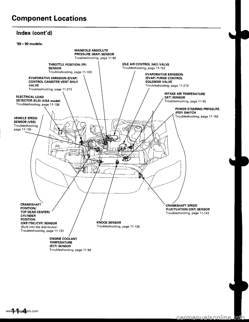
Component Locations
Index (cont'dl
39 - 00 models:
MANIFOLD ABSOLUTEPRESSURE IMAPISENSORTroubleshooting, page 1 1-90
THROTTLE POSITION {TP)SENSORTroubleshooting, page 1 1-103
IDLE AIR CONTROL OACI VALVETroubleshooting, page 1 1-152
EVAPOBATIVE EMISSION {EVAPICONTROL CANISTER VENT SHUTVALVETroubleshooting, page 1 1-213
EVAPORATIVE EMISSION(EVAPI PURGE CONTROI-SOLENOID VALVETroubleshootang, page 1 1-2'13
ELECTRICAL LOAOOETECTOR {ELD) IUSA modet)Troubleshooting, page I 1-138
INTAKE AIR TEMPERATURE(IAT) SENSORTroubleshooting, page 11 95
POWEB STEERING PRESSUREtPsPt swtTcHTroubleshooting, page 11 162VEHICLE SPEEDSENSOR IVSSITroubleshooting,page 11'135
CRANKSHAFTPOSTTTON/TOP OEAD CENTER/CYLINDERPOStTtON{CKP/TDC/CYP) SENSOR(Built into the distributor)Troubleshooting, page 11 131
CRANKSHAFT SPEEDFLUCTUATION ICKN SENSORTroubleshooting, page 1 1-142
SENSORTroubleshooting, page '11 130
ENGINE COOLANTTEMPERATURE{ECT)SENSORTroubleshooting, page 11 99
11-4
www.emanualpro.com
Page 208 of 1395
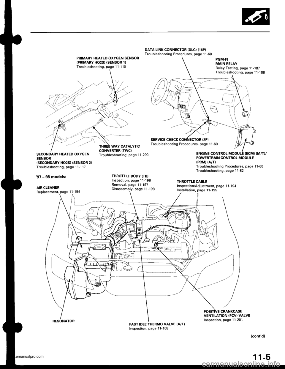
DATA LINK CONNECTOR {DLC) I16P}Troubleshooting Procedures, page 1 1'60PRIMARY HEATED OXYGEN SENSOR
{PRIMARY HO2SI {SENSOR 1)Troubleshooling, page 11 110
SECONDARY HEATED OXYGENSENSOR{SECONDARY HO2S) {SENSOR 2)Troubleshooting, page 1 1-1 17
'97 - 98 models:
AIR CLEANERReplacement, page 1 1'194
Troubleshooting, page 1 'l -200
THROTTLE BODY (TB)Inspection, page 11 196Removal, page 11-197Disassembly, page 1 1-'198
POWERTRAIN CONTROL MODULE(PCM) (A/TI
Troubleshooting Procedures, page 1 1-60Troubleshooting. page 1 1'82
THROTTLE CABLEInspection/Adjustment, page 1 1-1 94Installation, page 11- 195
VENTILATION (PCV) VALVEInspection, page 1 1-201FAST IDLEVALVE (A/T}
(cont'd)
1 1-5
PGM-FIMAIN RELAYRelay Testing, page 11-l87Troubleshooting. page 1'1 188
SERVICE CHECK CONNECTOR {2PITroubleshooting Procedures, page 1 1-60
,a'=_-_
WAY CATALYTIC
Inspection, page 1 1-168
www.emanualpro.com
Page 209 of 1395
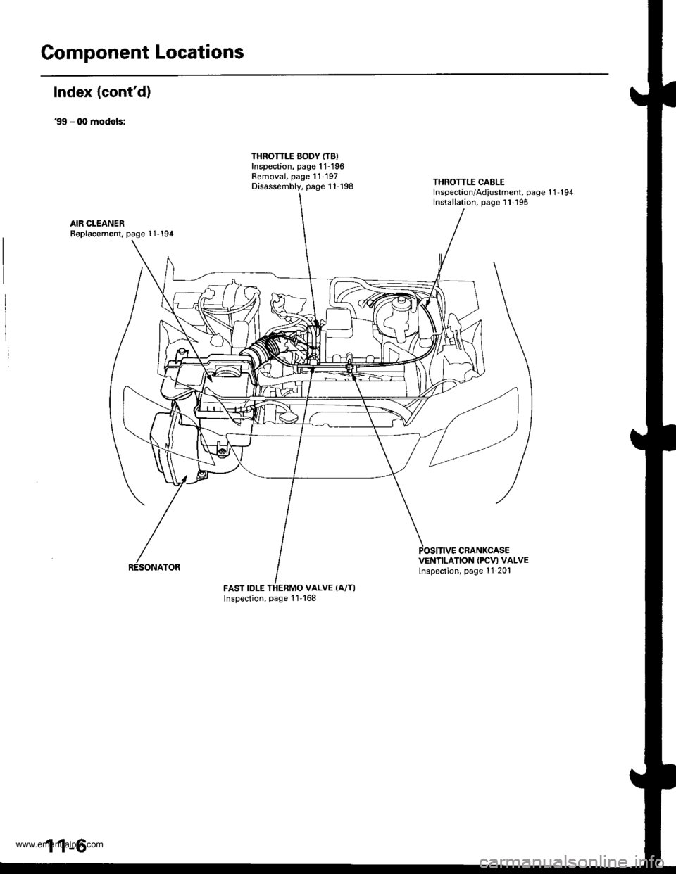
Component Locations
Index {cont'd)
39 - q, models:
THROTTLE BODY ITB)Inspection, page 1 1-196Removal, page 11- 197Disassembly, page 11 198THROTTLE CABLEInspectaon/Adjustment, page 1 1 194Installation, page I l'195
AIR CLEANERR€placomenl, page 1 1-194
CRANKCASEVENTILATION IFCVI VALVElnspection, page 11 201
FAST IDLE THERMO VALVE IA/T)Inspection, page 11'168
1 1-6
www.emanualpro.com
Page 210 of 1395
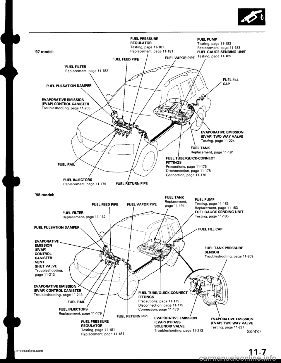
FUEL PRESSUREREGULATORTesting, page 11-181Replacement, page 11 181
FUEL PUMPTesting, page 11 183Replacement, page 11 183FUEL GAUGE SENDING UNITTesting, page 11 185
'97 model:
'98 model:
FUEL PULSATION DAMPER
EVAPORATIVE EMISSIONIEVAP) CONTROL CANISTERTroubleshooting. page 1'l-205
FUEL FILTERReplacement, page 11 182
FUEL INJECTORSReplacement, page 1 1-179
FUEL FEED PIPEFUEL VAPOR PIPE
FUELFITTINGS
FUEL FILLCAP
EVAPORATIVE EMISSION
IEVAPI TWO WAY VALVETesting, page 11 224
TANKReplacement, page 11 191
-CONNECT
Precautions, page 1 1-175Disconnection, page 11 175Connection, page 1 1-176
FUEL FILTERReplacement, page 11 182
FUEL FEED PIPEFUEL VAPOR PIPE
FUEI- TANKReplacement,page 1l 191
FUEL TUBE/OUICK.CONNECTFITTINGSPrecautions, page 11 '175
Disconnection, page 11 175Connection, page 11 176
FUEL PUMPTesting, page 11 183Replacement, page 11 183FUEL GAUGE SENDING UNITTesting, page 1l'185
FUEL FILL CAP
FUEL TANK PRESSURESENSORTroubleshooting, page 1 l-209
FUEL PULSATION DAMPER
EVAPORATIVEEMTSSTONIEVAPICONTROLCANISTERVENTSHUT VALVETroubleshooting,page 11'213
EVAPORATIVE EMISSIONIEVAPI CONTROL CANISTERTroubieshooting, page 1 1 -213
FUEL RAIL
FUELFeplacement, page 1 1-179
FUEL PRESSURENEGULATORTesting, page 11-181Replacement, Page 11 181
EVAPORATIVE EMISSION{EVAP) EYPASSSOLENOID VALVETroubleshooting, page 1 1'213
€VAPORATIVE EMISSION{EVAP) TWO WAY VALVETesting, page 11 224(cont'd)
www.emanualpro.com
Page 211 of 1395
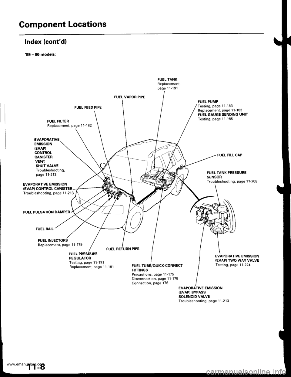
Gomponent Locations
Index lcont'd)
'99 - (X) modols:
FUEL TANKReplacement,page 11-191
FUEL FEED PIPE
FUEL FILTERReplacement, page 11 182
FUEL VAPOR PIPE
FUELFITTINGS
FUEL PUMPTesting, page '11 183Replacement, page 1 1_183FUEL GAUGE SENDING UNITTesting, page 11-185
FUEL FILL CAP
EVAPORATIVE EMISSIONIEVAP) CONTROLTroubleshooting, page 1 1-213
FUEL PULSATION DAMPER
FUEL RAIL
FUELReplacement, page 1 1-179
EVAPORATIVEEMtSStON
IEVAP)CONTROLCANISTERVENTSHUT VALVETroubleshooting,page 11-213FUEL TANK PRESSURESENSORTroubleshooting, page 1'l'208
EVAPORATIVE EMISSION{EVAP) TWO WAY VALVETesting, page 11-224
FUEL PRESSUREREGULATORTesting, page 11-181Replacement, page 11 181,CONNECT
PrecaLrtions, page 1 1-175Disconnection, page 1 1-175Connection, page 176
EVAPORATIVE EMISSION{EVAPI BYPASSSOLENOID VALVETroubleshooting, page 11 213
www.emanualpro.com