Bŕeak HONDA CR-V 1998 RD1-RD3 / 1.G User Guide
[x] Cancel search | Manufacturer: HONDA, Model Year: 1998, Model line: CR-V, Model: HONDA CR-V 1998 RD1-RD3 / 1.GPages: 1395, PDF Size: 35.62 MB
Page 988 of 1395
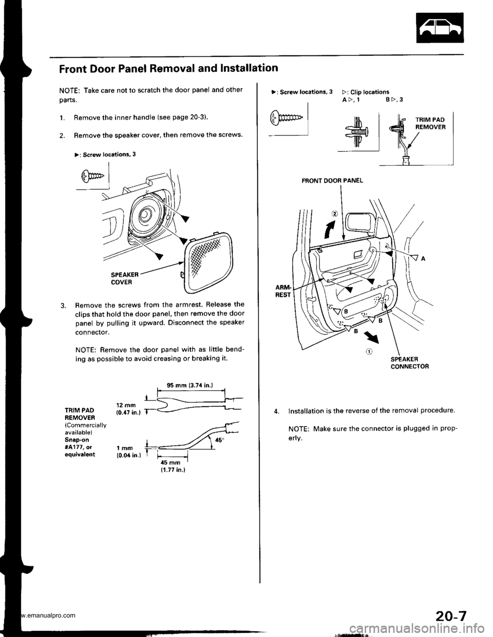
Front Door Panel Removal and Installation
NOTE: Take care not to scratch the door panel and other
pans.
L Remove the inner handle (see page 20-3).
2. Remove the speaker cover, then remove the screws.
>: Scr€w locations, 3
SPEAKERCOVER
Remove the screws from the armrest. Release the
clips that hold the door panel, then remove the door
panel by pulling it upward. Disconnect the speaker
connector.
NOTE: Remove the door panel with as little bend-
ing as possible to avoid creasing or breaking it.
TRIM PADREMOVER(Commercially
avaalable)Snap-on*4177, olequivalent
'..4'
,mm +,----ZY"{0.04 in.) r F -i45 mm I
{1.77 in.}
>: Screw location3,
I
eF** Iffil$;^r*l-w.
ttv IilF:I
3 >:Clip locttionsA>, 1 g>,3
FRONT OOOR PANEL
lnstallation is the reverse of the removal procedure.
NOTE: Make sure the connector is plugged in prop-
efly.
20-7
www.emanualpro.com
Page 992 of 1395
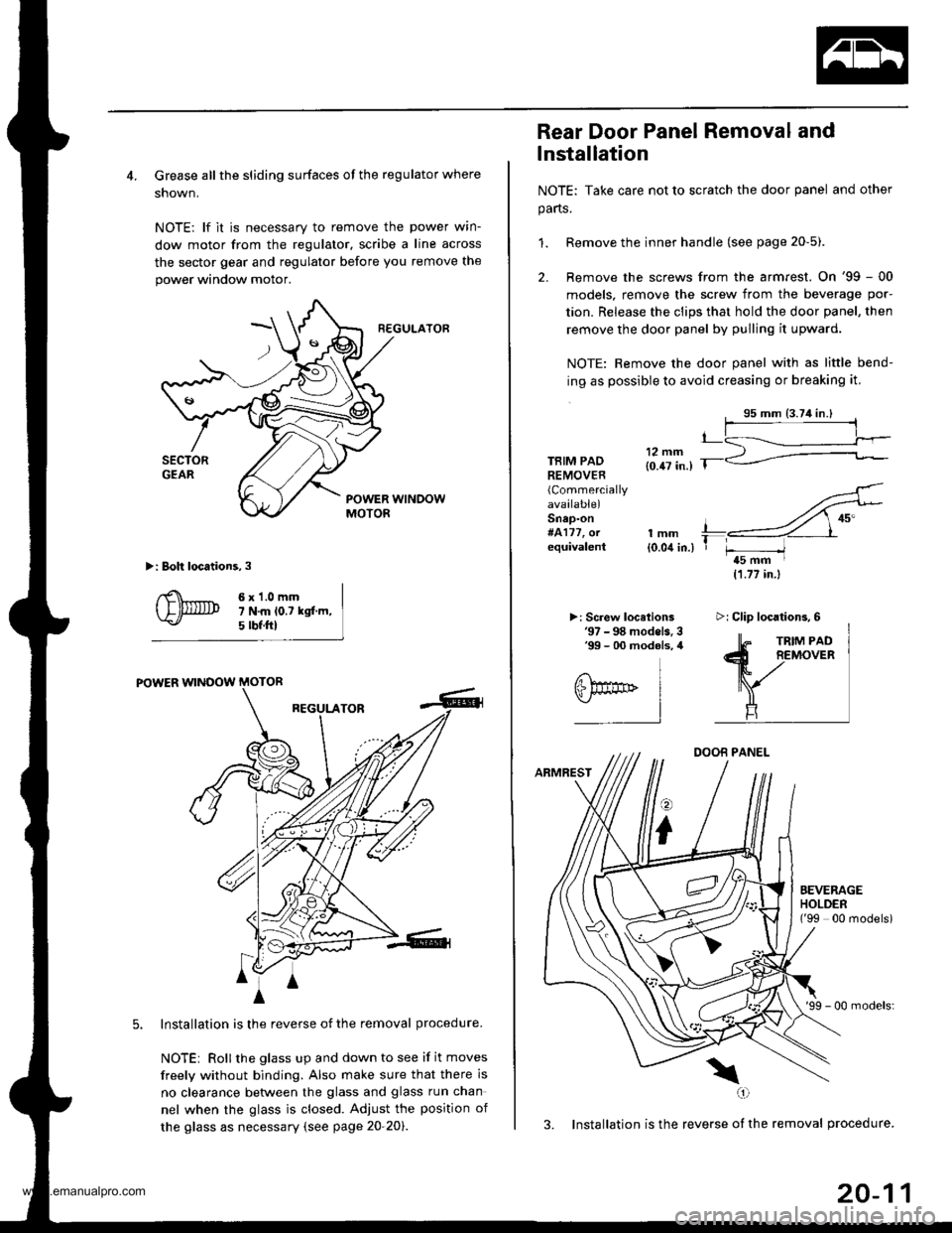
4. Grease all the sliding surfaces of the regulator where
shown.
NOTE: lf it is necessary to remove the power wrn-
dow motor from the regulator, scribe a line across
the sector gear and regulator before you remove the
power window motor.
R€GULATOF
>: Boh locations,3
6x1.0mm7 N.m lo.t kgf.m,5 tbf.ftl
POWER WINOOW MOTOR
REGULATOR
Installation is the reverse of the removal procedure.
NOTEi Rollthe glass up and down to see if it moves
freely without binding. Also make sure that there is
no clearance betlveen the glass and glass run chan
nel when the glass is closed. Adjust the position of
the glass as necessary (see page 20-20).
4
A
m^i
A
Rear Door Panel Removal and
lnstallation
NOTE: Take care not to scratch the door panel and other
parts.
1. Remove the inner handle (see page 20-5).
2. Remove the screws from the armrest. On '99 - 00
models, remove the screw from the beverage por-
tion. Release the clips that hold the door panel, then
remove the door panel by pulling it upward.
NOTE: Remove the door panel with as little bend-
ing as possible to avoid creasing or breaking it.
TBIM PADREMOVER(Commercially
available)Snap-on#4177, orequivalentlmm{0.04 in.)
>: Screw locelions'97 - 98 models. 3'99 - 00 modols, 4
11.77 in.)
DOOB PANEL
ARMREST
o
i
'99 - 00 models:
3. Installation is the reverse of the removal procedure.
\(,1
t_
T r-----/t5 mm I
EEVERAGEHOLDEN('99 00 modelsi
>i Clip locations,6
20-11
www.emanualpro.com
Page 1011 of 1395
Glass
Windshield Replacement
CAUTION:
. Put on gloves to protect your hands.
. Use seat covers to avoid damaging any surfaces.
1. To remove the windshield, first remove the:
. Rearview mirror (see page 20-28)
. Sunvisors and holders (see page 20-44l'
. Ceiling light (see section 23)
. Grab handle (see page 20-44)
. Front door trim (see page 20-41)
. Front pillar trim (see page 20-41)
. Windshield wiper arms and cowl cover (see page
20-98)
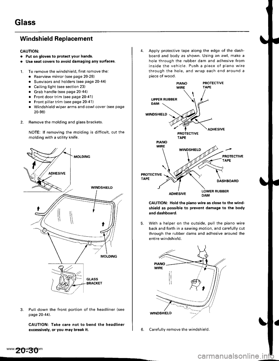
2. Remove the molding and glass brackets.
NOTE: lf removing the molding is difficult, cut the
moldlng with a utility knife.
MOLDING
3. Pull down the front Dortion of the headliner (see
page 20-44).
CAUTION: Take care not to bend the headliner
excessivsly, or you may break it.
WINDSHIELD
20-30
4. Apply protective tape along the edge ot the dash-
board and body as shown. Using an awl, make a
hole through the rubber dam and adhesive from
inside the vehicle. Push a piece of piano wire
through the hole, and wrap each end around a
piece of wood.
PROTECTIVETAPE
WINDSHIELD
ADHESIVE
PIANOWIRE
PROTECTIVETAPE
WINDSHIELO
PROTECTIVETAPEDASHBOARD
ADHESIVELOWER RUBBERDAM
CAUTION: Hold the piano wire as close to the wind-
shield as possible to prevent damage to the body
and dashboard.
5. With a helper on the outside, pull the piano wire
back and fo(h in a sawing motion, and carefully cut
through the rubber dams and adhesive around the
entire windshield.
6. Carefully remove the windshield.
UPPER RUBBER
PIANO
www.emanualpro.com
Page 1164 of 1395
Troubleshooting
Tips and Precautions (cont'dl
Insen the connector all the way and make sure it is
securely Iocked.
Position wires so that the open end of the cover faces
down.
V
Faceopen end
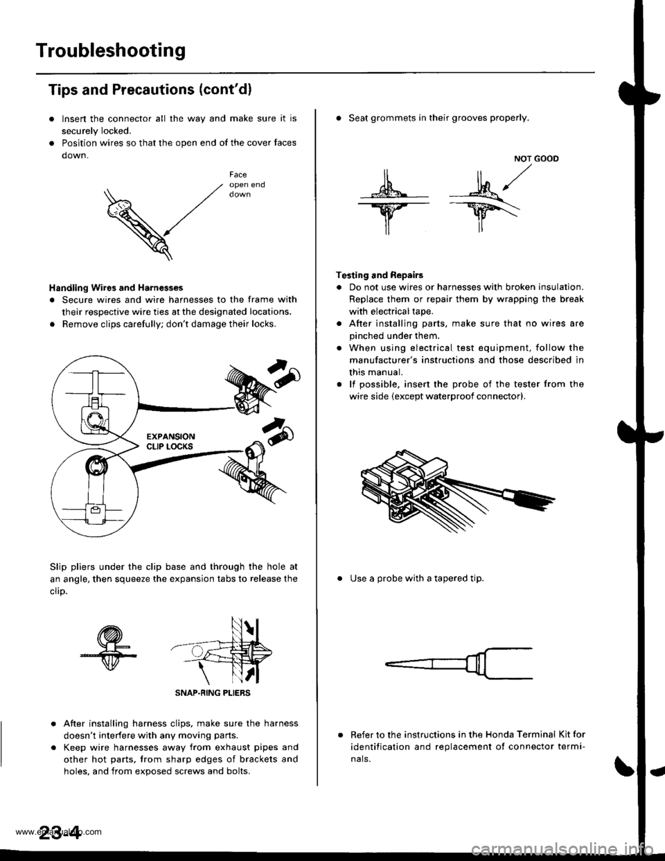
Handling Wires and Harnesges
. Secure wires and wire harnesses to the frame with
their respective wire ties at the designated locations.
. Remove clips carefully; don't damage their locks.
Slip pliers under the clip base and through the hole at
an angle, then squeeze the expansion tabs to release the
clrD.
After installing harness clips, make sure the harness
doesn't interfere with any moving pans.
Keep wire harnesses away from exhaust pipes and
other hot parts, trom sharp edges of brackets and
holes. and from exoos€d screws and bolts.
NOT GOOD
A -M/
lr lr*
T€sting and Repairs
. Do not use wires or harnesses with broken insulation.
Replace them or repair them by wrapping the break
with electricaltape.
. After installing parts, make sure that no wires are
pinched under them.
. When using electrical test equipment, follow the
manufacturer's instructions and those described in
this manual.
. lf possible, insert the probe of the tester from the
wire side (except waterproof connector).
. Seat grommets in their grooves properly.
. Use a probe with a tapered tip.
Refer to the instructions in the Honda Terminal Kit for
identification and replacement of connector termi-
nals.
www.emanualpro.com
Page 1272 of 1395
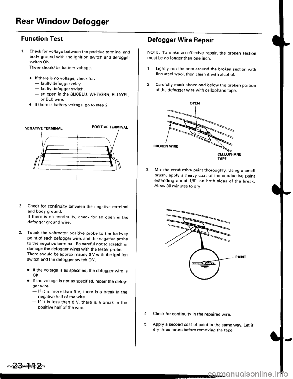
Rear Window Defogger
Function Test
1. Check for voltage between the positive terminal andbody ground with the ignition switch and defoggerswitch ON.
There should be battery voltage.
. lf there is no voltage. check for:- faulty defogger relay.- faulty defogger switch.- an open ,n the BLK/BLU, WHT/GRN, BLU/YEL,
or BLK wire.
. lf there is battery voltage, go to step 2.
POSITIVE TERMINAL
Check for continuity between the negative terminaland body ground.
lf there is no continuity, check for an open in thedefogger ground wire.
Touch the voltmeter positive probe to the halfwaypoint of each defogger wire, and the negative probe
to the negative terminal. Be careful not to scratch ordamage the defogger wires with the tester probe.There should be approximately 6 V with the ignitionswitch and the defogger switch ON.
. lf the voltage is as specified, the defogger wire isoK.
. lf the voltage is not as specified, repair the defog-ger wire.- lf it is more than 6 V, there is a break in thenegative half of the wire.- lf it is less than 6 V, there is a break in thepositive half of the wire.
23-112
Defogger Wire Repair
NOTE: To make an effective repair, the broken sectionmust be no longer than one inch.
1. Lightly rub the area around the broken section withfine steel wool, then clean it with alcohol.
2. Carefully mask above and below the broken portionof the defogger wire with cellophane tape.
CELLOPHANETAPE
Mix the conductive paint thoroughly. Using a smallbrush, apply a heavy coat of the conductive paint
extending about 1/8" on both sides of the break.Allow 30 minutes to dry.
Check for continuity in the repaired wire.
Apply a second coat of paint in the same way. Let itdry three hours before removing the tape.
5,
OPEN
www.emanualpro.com
Page 1319 of 1395
Precautions/Procedures
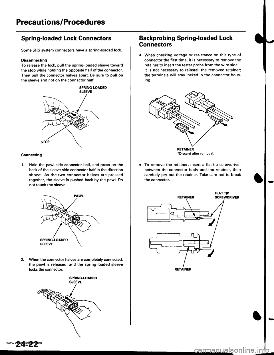
Spring-loaded Lock Connectors
Some SRS system connectors have a spring-loaded lock.
Disconnecting
To release the lock, pull the spring-loaded sleeve toward
the stop while holding the opposite halt of the connector.
Then pull the connector halves apart. Be sure to pull on
the sleeve and not on the connector half.
SPRING-LOADEDSLEEVE
Connecting
1. Hold the pawl-side connector hall and press on the
back of the sleeve-side connector half in the direction
shown. As the two connector halves are Dressed
together, the sleeve is pushed back by the pawl. Do
not touch the sleeve.
When the connec-tor halves are completely connected,
the pawl is released. and the spring-loaded sleeve
locks the connector.
SPRING.LOAI'ED
24-22
Backprobing Spring-loaded Lock
Connectors
. When checking voltage or resistance on this type of
connector the first time, it is necessary to remove the
retainer to insert the tester probe from the wire side.
It is not necessary to reinstall the removed retainer;
the terminals will stay locked in the connector hous-
inq.
To remove the retainer, insert a tlat-tip screwdriver
between the connector body and the retainer. then
carefully pry out the retainer. Take care not to break
the connector.
RETAINER*Discard after removal.
RETAINEN
RETAINER
---
www.emanualpro.com