Iac valve HONDA CR-V 1998 RD1-RD3 / 1.G User Guide
[x] Cancel search | Manufacturer: HONDA, Model Year: 1998, Model line: CR-V, Model: HONDA CR-V 1998 RD1-RD3 / 1.GPages: 1395, PDF Size: 35.62 MB
Page 280 of 1395
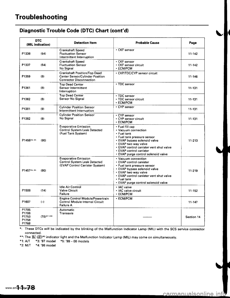
Troubleshooting
Diagnostic Trouble Code (DTCI Ghart (cont'd)
r: These DTCS will be indicated by the blinking oJ the Malfunction Indicator Lamp (MlL) with the SCS service connectorconnected.**: The Di (E)*5 indicator light and the Malfunction tndicator Lamp (MlL) may come on simultaneously.*1: A[f *3;'97 model *5: '99 - 00 models*21M/f *4: '98 model
11-78
DTC
{MlL indication}Detection ltemProbable CausePagc
P1336 154)Crankshaft SpeedFluctuation SensorIntermittent Interruption
. CKF sensor
11-142
P1337 i54)Crankshaft SpeedFluctuation SensorNo Signal
CKF sensorCKF sensor circuitECM,FCM11-142
P1359 (8)Crankshaft Position/Too DeadCenter Sensorrcylinder PositionConnector Disconnection
' CKP/TDC/CYP sensor circuit11-146
P1361 (8)Top Dead CenterSensor IntermittentInterruption11-131
P1362 (8)Top Dead CenterSensor No SignalTDC sensorTDC sensor circuitECM/PCM11-131
P1381 (9)Cylinder Position SensorIntermittent Interruption
. CYP sensor11-131
P1382 (9)Cylinder Position SensorNo SignalCYP sensorCYP sensor circuitECM/PCM11-131
P1456n.* {90}
Evaporative EmissionControl System Leak Detected(FuelTank System)
Fuelfill capVacuum connectionFueltankFuel tank prossure sensorEVAP bypass solenoid valveEVAP two way valveEVAP control canister vent shut valveEVAP control canisterEVAP purge controlsolenoid valve
11-213
Pr457n.s {90)
Evaporative EmissionControl System Leak Detected(EVAP Control Canister Svstem)
Vacuum connectionEVAP control canisterFuel tank pressure sensorEVAP bypass solenoid valveEVAP two way valveEVAP control canister vent shut valveFueltankEVAP purge controlsolenoid valve
11-219
P1508 (14)ldle Air ControlValve CircuitFailure
IAC valveIAC valve circuitECM/PCM11-152
Pr607(-)Engine Control Module,PowertrainControl Module Internal CircuitFailure A
. ECM,FCM11-147
P1705P1706P1753P1758P1768
AutomaticTransaxle
Section '14
www.emanualpro.com
Page 282 of 1395

PGM-FI System
System Description
INPUTS
CKP/TDC/CYP Sensor
CKF Sensor
MAP Sensor
ECT Sensor
IAT Sensor
TP Sensor
Primary HO2S
Secondary H02S
vss
KS*5
BARO Sensor
ELD*6
Starter Signal
ALT FR Signal
Air Conditioning Signal
Ay'T Gear Position Signal*1
Baftery Voltage (lGN.1)
Brake Switch Signal
PSP Switch Signal
Fuel Tank Pressuae Sensor*4. *5
Countershaft Speed Sensor*1
Mainshaft Speed Sensor*r
OVER-DRIVE Switch Signal*s
ENGINE CONTROL MODULE (ECM)/
POWERTRAIN CONTROL MODULE (PCM) OUTPUTS
|iuel 1"j""- Th,rhg ""d Drrafr";-l
Et*-.nt"tdt"cont.orl
to,r*,c;;trffi;]
l.----.---:. .Lrgnrnon |lmrng Lonrror I
Ecir/PcM B*k',p Fr""il]
m;"t-ll-r*'io*l
Fuel Injectors
PGM-Fl Main Relay (Fuel Pump)
MIL
IAC Valve
Ay'C Compressor Clutch Relay
Radiator Fan Relay
Condenser Fan Relay
ALT
tcM
EVAP Purge Control Solenoid
Valve
Primary HO2S Heater
Secondary H02S HeaterEVAP Bypass Solenoid Valve*a *5
EVAP Control Canister Vent Shut
DLC
Lock-up Control Solenoid Valve*l
Shift Control Solenoid Valve*1
Ay'T Clutch Pressure Control
Solenoid Valve*1
D4 Indicator Light'1 *3, *a
D Indicator Light,l *5
OVER-DRIVE OFF Indicator
Lighl*t *:
*1: A/T {3:'97 model'2: M/f +4:'98 model*5: '99 - 00 models"6: USA
PGM-Fl System
The PGM-Fl system on this model is a sequential multiport fuel injection system.
Fuel iniecior Timing and Duration
The ECM/PCM contains memories for the basic discharge durations at various engine speeds and manifold pressure. The
basic discharge duration, after being read out from the memory, is further modified by signals sent from various sensors
to obtain the final discharge duration.
ldle Air Control
ldle Air Control Valve (lAC Valve)
When the engine is cold, the Ay'C compressor is on, the transmission is in gear, the brake pedal is depressed, the P/S load
is high, or the alternator is charging, the ECM/PCM controls current to the IAC Valve to maintain the correct idle speed.
lgnition Timing Control
o The ECM/PCM contains memories for basic ionition timing at various engine speeds and manifold air flow rates.
lgnition timing is also adjusted for engine coolant temperature.
. A knock control system was adopted which sets the ideal ig nition timing for the octane rating of the gasoline used.*s
Other Control Funstions
1. Starting Control
When the engine is started. the ECM/PCM provides a rich mixture by increasing fuel injector duration.
2. Fuel Pump Control
. When the ignition switch is initially turned on (ll). the ECMiPCM suppli€s ground to the PGM-FI main relay that
supplies current to the fuel pump for two seconds to pressurize the fuel system.
. When the engine is running, the ECM/PCM supplies ground to the PGM-FI main relay that supplies current to the
fuel oumo.
. When the engine is not running and the ignition is on, the ECM/PCM cuts ground to the PGM-FI main relay which
cuts current to the fuel pump.
1 1-80
www.emanualpro.com
Page 287 of 1395
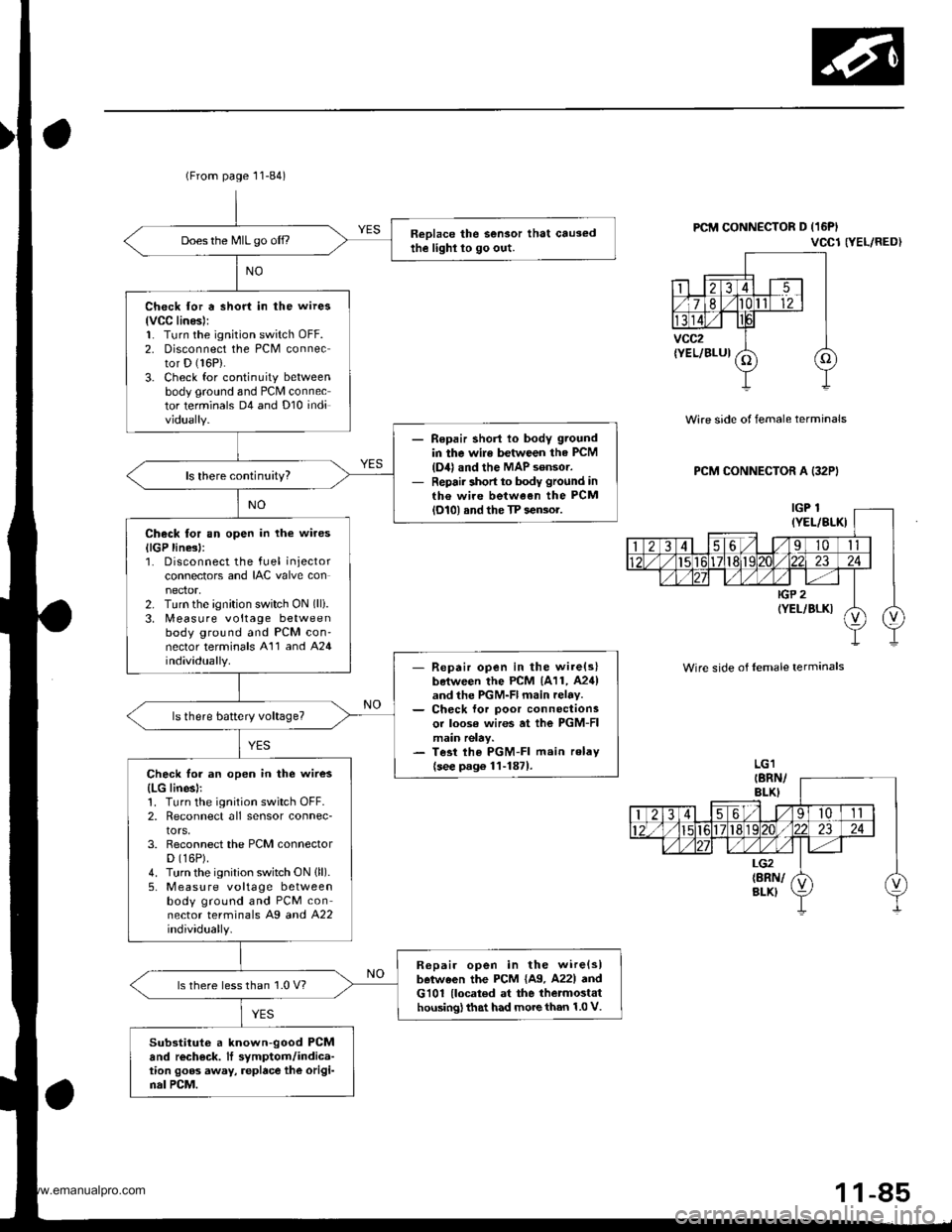
(From page 11-84)
Reolace the Sensor that causedthe lighl lo go out.Does the MIL go off.,
Check for a short in the wires
lvCC linesl:1. Turn the ignition switch oFF.2. Disconnect the PCM connector D (16P).
3. Check for continuity betweenbody ground and PCM connector terminals D4 and Dl0 individually.
Repair shorl lo body ground
in the wile between the PCM
{D4} and the MAP sensor.Repair short to body ground inth€ wire between the PCMlol0l and the TP sensor.
Check tor an open in the wires
llGP line3l:1. Disconnect the fuel injectorconnectors and IAC valve con
2. Turn the ignition switch ON (lli.
3. [,4easure voltage betweenbody ground and PCM con'nector terminals A'11 and A24individually.- Repair open in the wire(slboiween the PCM 1A11, A24)and the PGM-Fl main relav.- Ch€ck lor poor connectionsor loose wires at ihe PGM-FImain relay.- Tesi lhe PGM-FI main relav
{see p.g6 1l-1871.Check for an open in the wires
{LG linesl:1. Turn the ignition switch OFF.2, Reconnect all sensor connec-tors,3. Reconnect the PCM connectorD (16P).
4. Turn the ignition switch ON (ll).
5, M easu re voltage betweenbody ground and PCM connector terminals Ag a^d 422individually.
R6pair open in the wire{slbetween the PCM {A9. A22l andG101 {located at the thetmostathousing) that had more than 1.0 V.
ls there less than 1.0 V?
Substituto a known-good PCMand rech€ck. It symptom/indica-tion goos away, replace the origi-nal PCM.
PCM CONNECTOR D (16PI
VCCl NEL/RED}
Wire side of female terminals
PCM CONNECTOR A (32PI
Wire side of lemale terminals
1 1-85
www.emanualpro.com
Page 289 of 1395
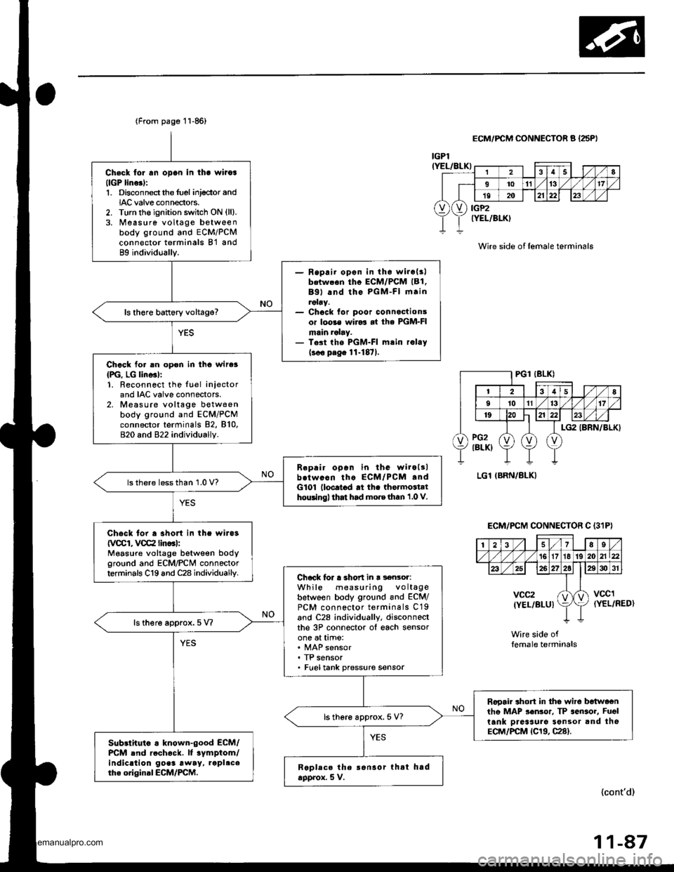
Ch€ck tor rn opon in tha wiioa(lGP lino.):1. Disconnectthe fuel inj€ctor andIAC valve connectors.2. Turn the ignition switch ON {ll}.3. Measure voltage betweenbody ground and ECM/PCMconn€ctor terminals B'l and89 individually.
- Repaii opon in th6 wirc{3lbetw.6n tho ECM/PCM (B1.
Bgl lnd tho PGM-FI mainroby.- Chock for poor connactionsor loo3€ wiJo3 at the PGM-FImain ralry.- T.st the PGM-FI mtin r.lay(soo p.ge 11-1871.
ls there battery voltage?
Chack for an opon in tho wire3
{PG, LG lino3l:1. Reconnect the luel iniectorand IAC valve connectors.2. Measure voltage betweenbody ground and ECM/PCMconnector terminals 82, 810,820 and 822 individually.
B.pair open in the wiroltlb.twocn tho ECM/PCM .ndG101 lloc.t6d rt th. thormoiathouingl that had mo.e than 1 .0 V.
lsthere lessthan 1.0 V?
Chock for a shon in the wira3
{VCCI, VCC2 lin..l:Measure voltage between bodyground and ECM/PCN4 connectorterminals C19 and C28 individuallv.Chock lor a short in r s€nsor:While measuring voltagebetwoen body ground and ECM/PCM connector terminals C19and C28 individually, disconneclthe 3P connector ol each sensorone at time:
. TP sensor. Fueltank pressure sensor
ls there approx.5 V?
Rooair ahort in tho wire b€twoentho MAP sen3or. TP sensor, Fuel
tank Dreaaure Sonsor and theECM/PCM tC19, C28).
ls there approx. 5 V?
Sub3lhuio . known-good ECM/PCM .nd rcch6ck. lf tymptom/indic.tion go.3 away, rapl.ceth. original ECM/PCM.Replece the ronsor thtt hadapprox. 5 V.
(From page 11-86)
lcont'd)
r
28
I1011't317
19202123
vXv) iiP2rELlBLK)
IGPl(YEL/BLK)
ECM/FCM CONNECTOR A {25PI
Wire side of lemale terminals
(YEL/RED)
Wire side oflemale terminals
ECM/PCM CONNECTOR C {3'IP}
| 2i37Es/'t61718 192021\22
26272elE30 31
vcc2(YEL/BLUIktvccl
11-47
www.emanualpro.com
Page 328 of 1395
PGM-FI System
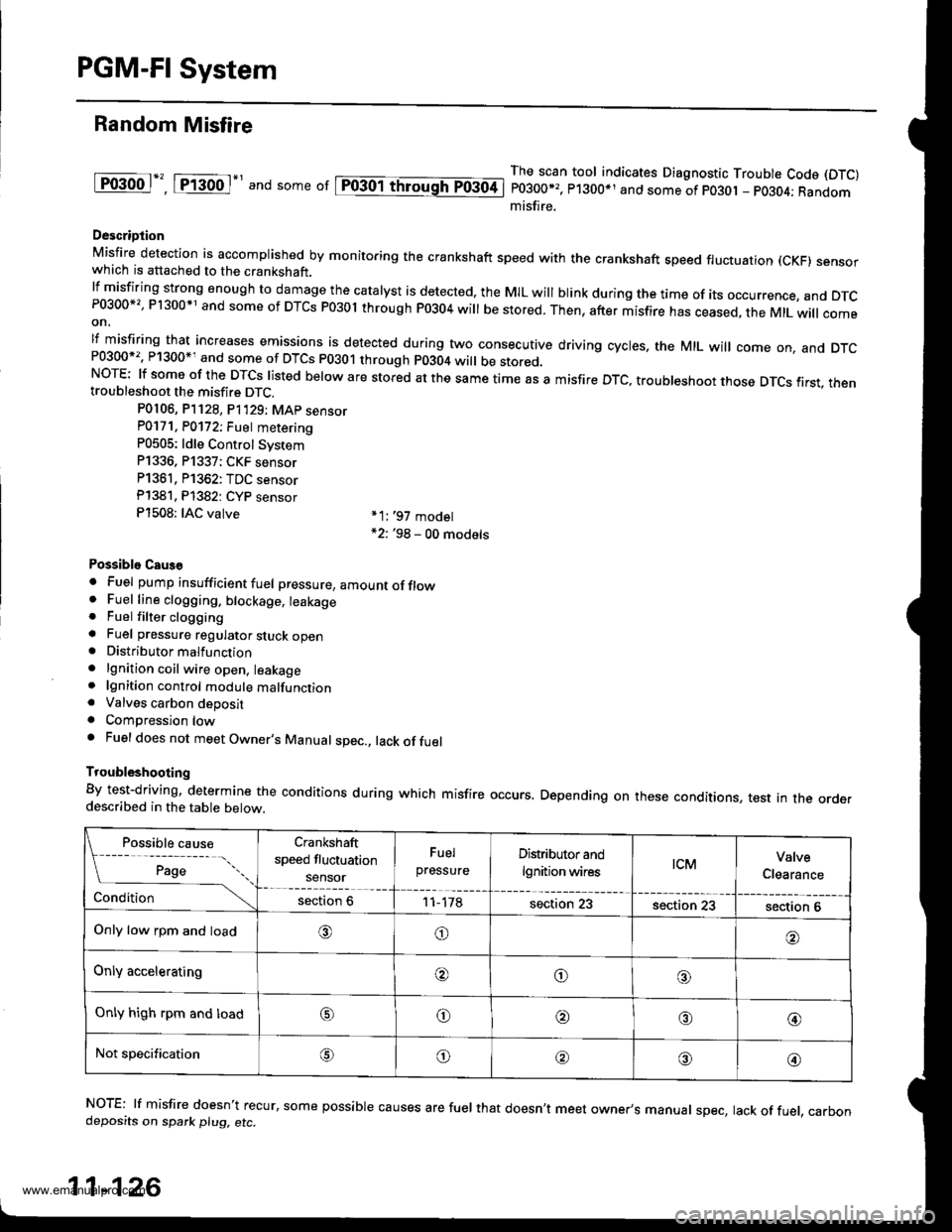
Random Misfire
lF()gool", tftod-' and some or lpiogol throughTo3oti
The scan tool indicates Diagnostic Trouble Code (DTC)
P0300*,, P1300*1 and some of po30t - pO3O4; Randommisfire.
Descriotion
Misfire detection is accomplished by monitoring the crankshaft speed with the crankshaft speed fluctuation (cKF) sensorwhich is attached to the crankshaft.lfmisfiring strong enough to damage the catalyst is detected, the MIL will blink during the time of its occurrence, and DTcP0300*'�, P1300*1 and some of DTCs P03ol through P0304 will be stored. Then, after misfire has ceased, the MtL will comeon,
lf misfiring that increases emissions is detected during two consecutive driving cycles, the MIL will come on, and DTcand some of DTCS p0301 through p0304 wi
be stored.NOTE: lf some of the DTCS listed below are stored at the same time as a misfire DTc, troubleshoot those DTcs first. thentroubleshoot the misfire DTC.
P0106, P]128, P1'129; MAp sensorP0171. P0172; Fuet metering
P0505: ldle Control Svstem
P1336, P1337; CKF sensor
P1361, P1362: TDC sensor
Pl381. Pl382: CYP sensor
P1508: IAC valve *1:,97 model*2: '98 - 00 models
Possiblo Caus€
. Fuel pump insufficient fuel pressure, amountofflow. Fuel line clogging. blockage, leakage. Fuel filter clogginga Fuel pressure regulator stuck open. Distributormalfunction
. lgnition coil wire open, leakage. lgnition control module malfunction. Valves carbon deposita Compression lowa Fuel does not meet Owner's Manual spec., lack offuel
Troubleshooting
By test-driving, determine the conditions during which misfire occurs. Depending on these conditions, test in the orderdescribed in the table below.
Possible cause
[ ;;;;- -....
Crankshaft
speed fluctuation
sensor
Fuel
pressureDistributor and
lgnition wirestcMValve
Clearance
Conditionsection 611-178section 23section 23section 6
Only low rpm and load,6)o
Only acceleratingooo
Only high rpm and loado@,a'@
Not specificationG\o@o@
NOTE: lf misfire doesn't recur, some possible causes are fuel that doesn't meet owner's manual spec, lack of fuel, carbondeposits on spark plu9, etc.
11-126
www.emanualpro.com
Page 351 of 1395
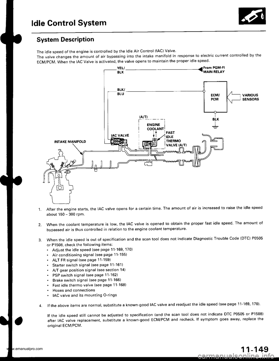
ldle Control System
System Description
The idle speed of the engjne is controlled by the ldle Air Control (lAC) Valve'
The valve changes the amount of air bypassing into the intake manifold in response to electric current controlled by the
ECM/PCM. When the lAc valve is activated, the valve opens to maintain the proper idle speed.
YEL/ From PGM'FI
BLK TMAIN RELAY
VARIOUSSENSORS
4.
IAC VALVE
INTAKE MANIFOLD
After the engine starts, the IAC valve opens for a certain time. The amount of air is increased to raise the idle speed
about 150 - 300 rpm.
when the cootant temperature ts row, the lAc valve is opened to obtain the proper fast idle speed The amount o{
bvoassed air is thus controlled in relation to the engine coolant temperature
When the idle speed is out o{ specification and the scan tool does not indicate Diagnostic Trouble Code (DTC) P0505
or P1508, check the following items:
. Adjust the idle speed (see page 11-169, 170)
. Air conditioning signal (seepagell-1551
. ALT FR signal (see page 1l-159)
. Starter switch signal (see page 11-16'1)
. A,/T gear position signal (see section 14)
. PSP switch signal (seepagell-162)
. Brake switch signal (see page 11-165)
. Fast idlethermovalve (see page'11 168)
. Hoses and connecttons. IAC valve and its mounting O-rings
lf the above items are normat, suDslitute a known-good IAC valve and readjust the idle speed {see page 11-169, 170)
lf the idle speed still cannot be adjusted to specification (and the scan tool does not indicate DTC P0505 or Pl508)
after IAC valve reolacement, substitute a known-good ECM/PCM and recheck lf symptom goes away' replace the
original ECM/PCM.
11-149
www.emanualpro.com
Page 352 of 1395

ldle Control System
ldle Control System
I P0505 | The scan tool indicates Diagnostic T.ouble Code (DTCI PO5O5: ldlecontrol svstem mattunction.
NOTE: lf DTC P1508 is stored at the same time as DTC P0505, troubleshoot DTC P1508 first. then troubleshoot DTC p0505.
Possibls Cause
. IAC valve mechanical malfunction. Throttle body clogged port, improper adlustment. Intake manifold gasket leakaging. Intake air hose loose leakaging. Vacuum hose leakaging
a ECT sensor incorrect output. Throttle Position sensor incorrect output
Troubleshooting Flowchart
The MIL has been reDorted on.DTC P0505 is sto.ed.
Problem verificationi1. Start the engine. Hold theengine at 3,000 rpm with noload (in Park or neutral) untilthe radiator Ian comes on, thenlet it idle.2. With the scan tool, check thelollowing items.- Throttle position should beapprox. 10% with the throt-tle {ully closed.- Engine coolant temperature shorJld be 194 - 205'F(90 - 96"C).lf they are not within thespec., repair the faulty sen-sor circuit.3 Check the engine speed atidle with no-load conditions:headlights, blower fan. reardefogger, radiator lan, and airconditioner are not operaling,
Inte.mittent failure. syltem is OKat this time.ls it 750 {730)* i 50 rpm?
ls il 700 (680)' rpm or less?
{To page 11-151)(To page 1'l-151)
l:'99 - 00 models
www.emanualpro.com
Page 353 of 1395
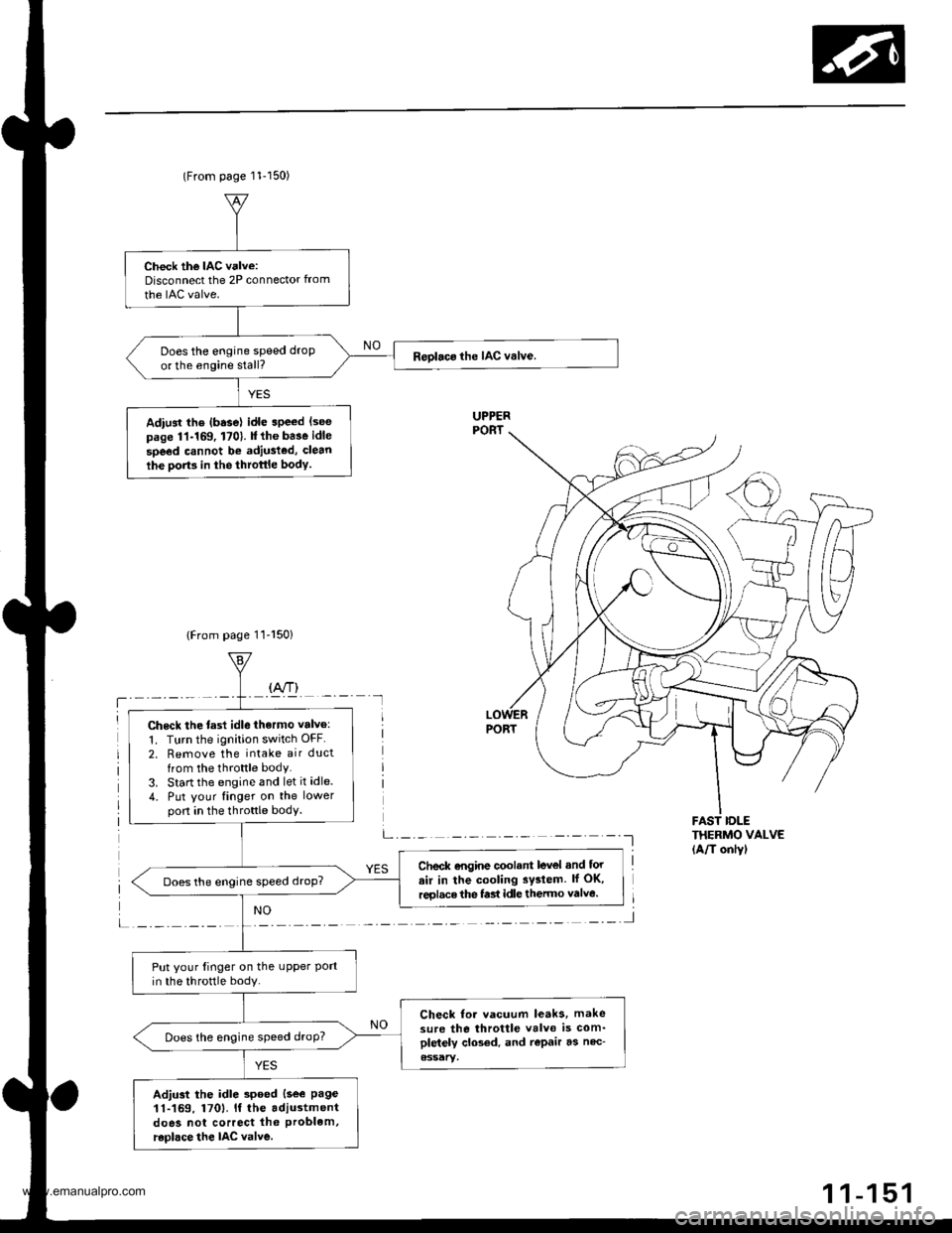
(From page 11-150)
{From page 11-150}
THERMO VALVE(A/T onlyl
Check the IAC valve:Disconnect the 2P connector from
the IAC valve.
Does the engine speed droP
or the engine stall?
Adiust the (basel idl€ speed lseepage 11-169, 1t0). Itihe ba3e idle
speed cannot be adiust€d, clean
the Dorts in the throttle body.
UPPER
Check the tast idle lhermo valve:
1. Turn the ignition switch OFF.
2. Remove the intake air ductfrom the throttle body.3. Start the engine and let it idle.
4. Put your finger on the lowerpon in the throttle body.
Check engine cool.nt level and for
air in the cooling sy3lem. lf OK,
reolace the f.st idle thermo valve.Does the engine speed drop?
Put your Iinger on the uPPer Portin the throttle body.
Check for vacuum leaks, make
sure the throttle valve is com'pletely clo3ed. and repair as nec-Does the engine speed droP?
Adjust the idle spoed lsee Page11-169. 1701. lf the adiustmentdoes not correct lhe problem,
r.olace the IAC valve.
www.emanualpro.com
Page 354 of 1395
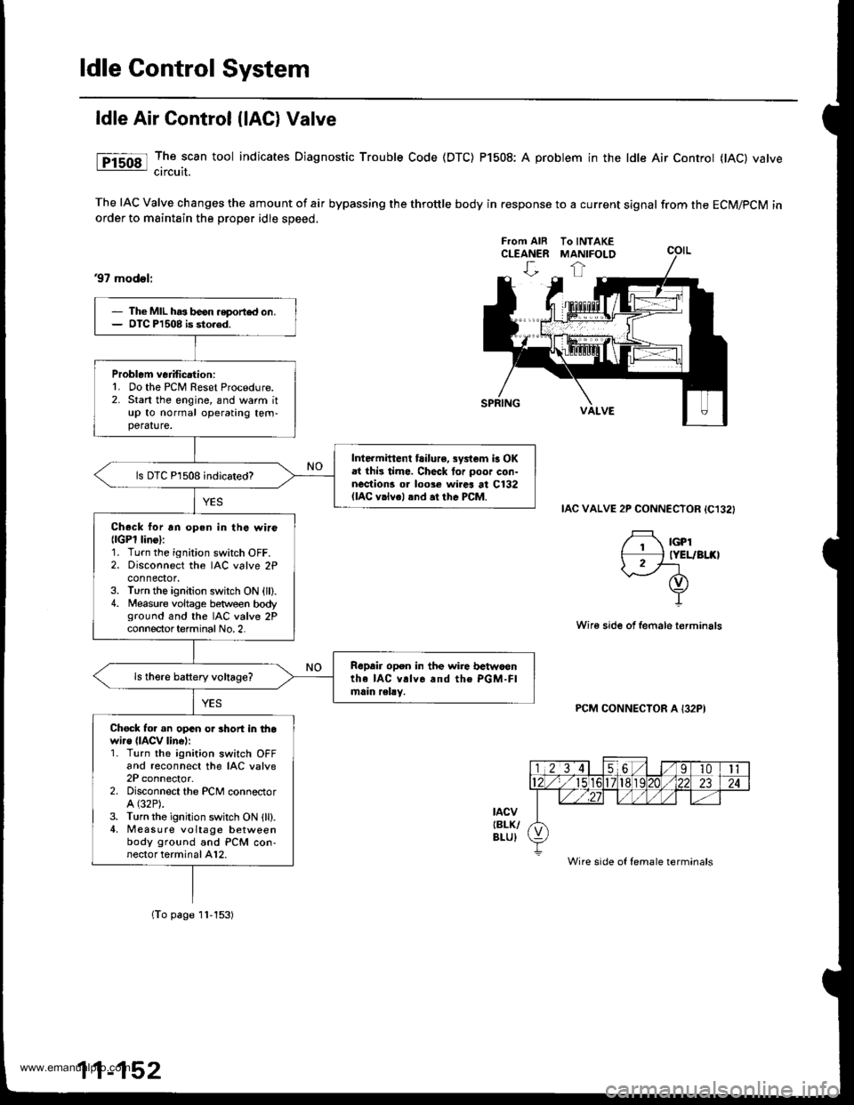
ldle Control System
ldle Air Control llAC) Valve
The scan tool indicates Diagnostic Trouble Code (DTC) Pl508: A probtem in the ldle Air Controt flAC) varvecircuit.
The IAC Valve changes the amount of air bypassing the throttle body in response to a current signal from the ECM/PCM inorder to maintain the proper idle speed.
37 model;
IAC VALVE 2P CONNECTOR {C132}
,f rcp'# IYEL/BI.(II2f-1-d)
Y
Wir€ side of female terminals
PCM CONNECTOR A I32PI
tacvIBLK/BLU)
From AIR To INTAKECLEANER MANIFOLD
Wire side of female terminals
The MIL has beon .eport€d on.OIC Pl508 is sto.ed.
Problem veiification:1. Do the PCM Reset Procedure.2. Start the engine, and warm itup to normal operating tem-perature.
Inte.mittent failure, systcm b OKat thi3 time. Check tor poo. con-nections or loose wircs at C132(lAC v.lvel and at the PCM.
ls DTC Pl508 indicated?
Check lor an open in the wir6{lGPl lins}:1. Turn the ignition switch OFF.2. Disconnect the IAC valve 2Pconnector.3. Turn the ignition switch ON {ll).4. Measure voltage between bodyground and the IAC valve 2Pconnector term inal No.2.
Repair open in the wire trctwoontha IAC v!lv6 and the PGM-Flmain relly.
Chock for an opan o. short in thowi.e (lACv linel:1. Turn the ignition switch OFFand reconnect the IAC valve2P connector.2. Disconnect the PCM conneclorA (32P).
3. Turn the ignition switch ON {ll).4, Measure voltage betweenbody ground and PCM con-nector terminal A12.
{To page 1l-153)
www.emanualpro.com
Page 355 of 1395
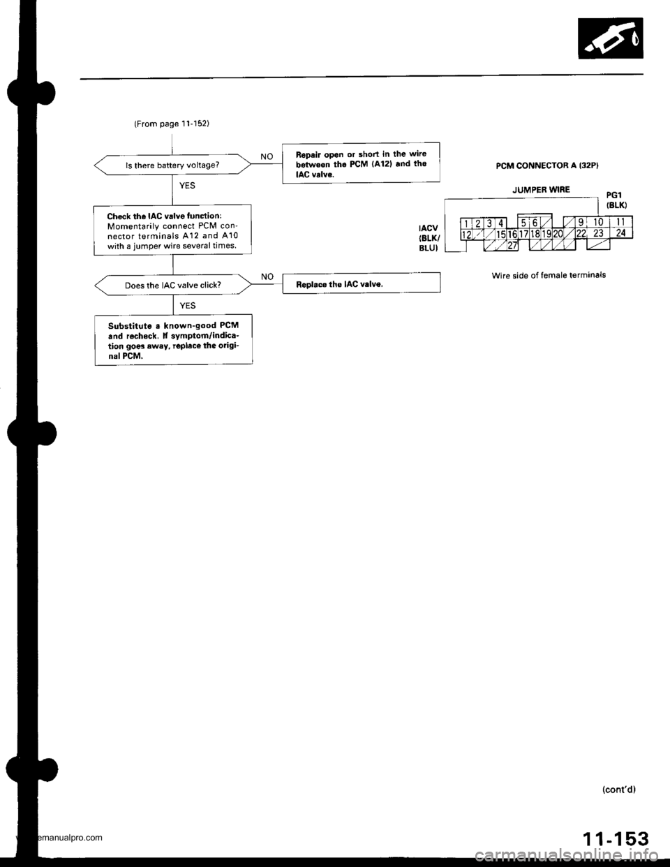
Bepair op€n or short in the wire
betweon th€ PCM {A121 and the
IAC vrlve.ls there baftery voltage?
Check the IAC valve function:Momentarily connect PCM con'nector terminals A12 and A10with a iumoer wire severaltimes,
Does the IAC valve click?
Substitute . known-good PCM
and r€check, lt 3ymptom/indica-tion goes away, replaco the origi_nalPCM,
(From page 11-152)
Wire side of female terminals
1-153
www.emanualpro.com