Vss HONDA CR-V 1998 RD1-RD3 / 1.G User Guide
[x] Cancel search | Manufacturer: HONDA, Model Year: 1998, Model line: CR-V, Model: HONDA CR-V 1998 RD1-RD3 / 1.GPages: 1395, PDF Size: 35.62 MB
Page 447 of 1395
Transmission Assembly
Removal (cont'dl
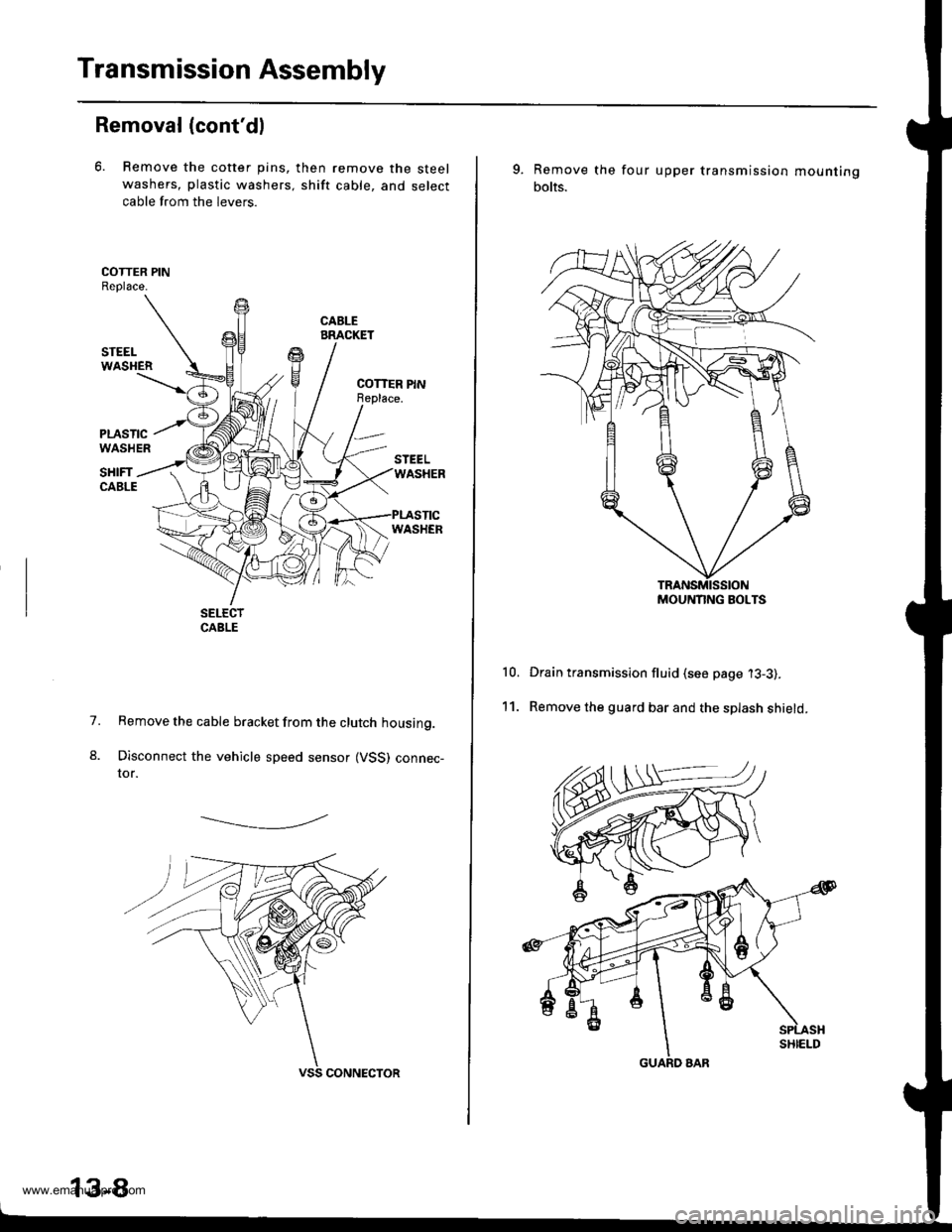
6. Remove the cotter pins,
washers, plastic washers.
cable from the levers.
then remove the steel
shift cable, and select
1.
8.
Remove the cable bracket from the clutch housing.
Disconnect the vehicle speed sensor (VSS) connec-tor.
-------------.2
13-8
9. Remove the
bolts.
four upper transmission mou nting
10.
11.
Drain transmission fluid (see page '13-3).
Remove the guard bar and the splash shield.
MOUNNNG BOLTS
www.emanualpro.com
Page 453 of 1395
Transmission Assembly
Disassembly
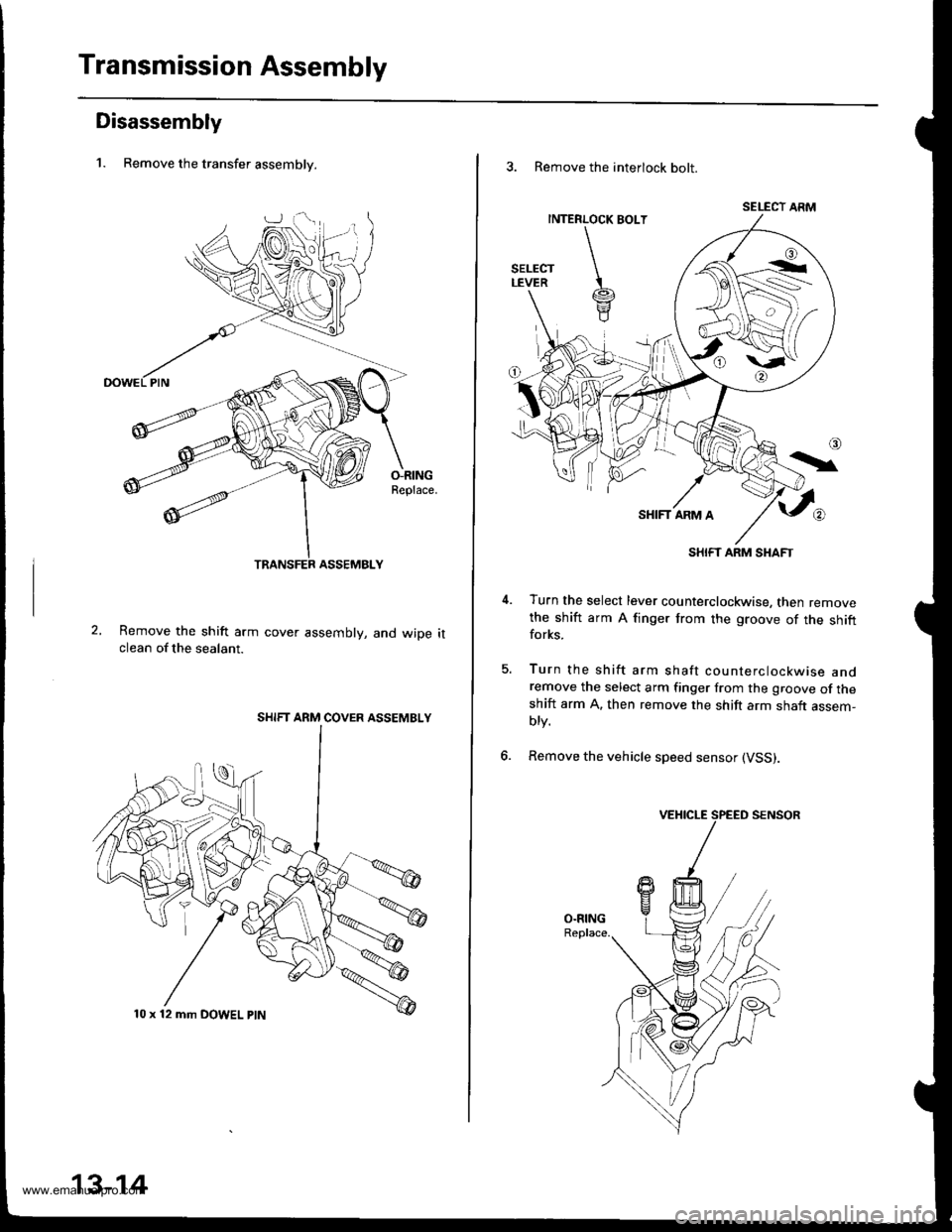
1. Remove the transfer assemblv.
O-RINGReplace.
Remove the shift arm cover assembly, and wiDe itclean of the sealant.
SHIFT ARM COVER ASSEMBLY
10 x 12 mm DOWEL ptN
13-14
3. Remove the interlock bolt.
SELECT ARM
SHIFT ARM SHAFT
Turn the select lever counterclockwise, then removethe shift arm A finger from the groove of the shiftforks.
Turn the shift arm shaft counterclockwise andremove the select arm finger from the groove of theshift arm A. then remove the shift arm shaft assem-blv.
Remove the vehicle speed sensor (VSS).
5.
6.
www.emanualpro.com
Page 509 of 1395
Transmission Assembly
Reassembly lcont'd)
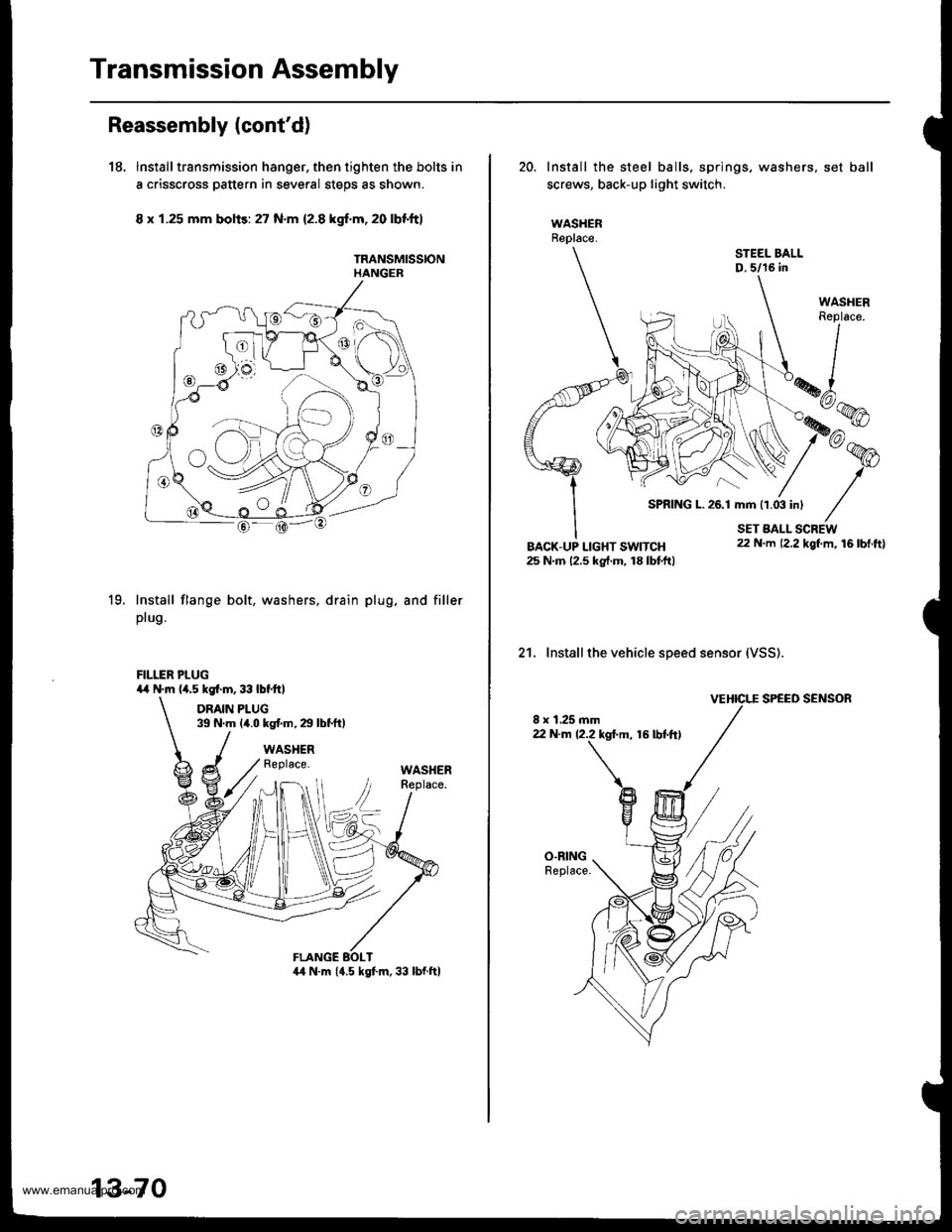
18. Installtransmission hanger, then tighten the bolts in
a crisscross pattern in several steps as shown.
8 x 1.25 mm bolis: 27 N.m 12.8 kgf.m,20 lbf'ft}
TRANSMISSIONHANGER
19.Install flange bolt,
plug.
washers, drain plug. and filler
FILLER PLUG4,r N.m (a.5 kgl.m,33lbtftl
DRAIN PLUG39 N.m {4.0 kg{.m,29lbtftl
WASHERReplace.WASHER
13-70
20. Install the steel balls, springs. washers, set ball
screws, back-up light switch.
WASHERReplace.
STEEL BALLD,5/16 in
21. Installthe vehicle speed sensor (VSS).
VEHICI."E SPEED SENSOR
8 x 1.25 mm22 N.m 12.2 kgl.m, 16 lbt.ftl
SPRING L.26.1 mm 11.03 inl
www.emanualpro.com
Page 514 of 1395
18.
19.
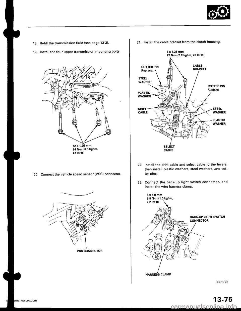
Refill the transmission fluid (see page 13-3)
Install the four upper transmission mounting bolts.
12 x 1.25 mm6it N.m 16.5 kgf m,il7 lbf.ftl
20. Connect the vehicle speed sensor (VSS) connector.
------------,-
VSS CONNECTOR
21, Install the cable bracket from the clutch housing.
8 x 1.25 mm27 N.m (2.8 kgt'm. 20 lbtftl
COTTER PINR€place.
STEELWASHER
COTTEN PINReplace.
STEELWASHER
PLASTICWASHER
22.
)a
SELECTCABLE
lnstall the shift cable and select cable to the levers,
then install plastic washers, steel washers, and cot-
ter prns,
Connect the back-up light switch connector. and
install the wire harness clamP.
6x1.0mm9.8 N.m {1.0 kgf.m,
HARNESS CLAMP
(cont'd)
13-75
www.emanualpro.com
Page 530 of 1395
Description
Power Flow (cont'dl
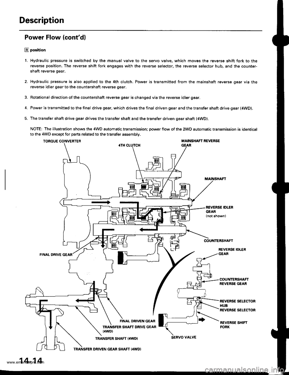
E position
1. Hydraulic pressure is switched by the manual valve to the servo valve, which movss the reverse shift fork to the
reverse position, The reverse shift fork engages with the reverse selector, the reverse selector hub, and the counter-
shaft reverse gear.
2. Hydraulic pressure is also applied to the 4th clutch. Power is transmitted from the mainshaft reverse gear via the
reverse idler gear to the countershaft reverse gear.
3. Rotational direction ofthe countershaft reverse gear ischanged viathe reverse idlergear.
4. Power is transmitted to the final drivegear,which drivesthefinal d riven gear a nd the transfer shaft drive gesr (4WD).
5. The transfer shaft drive gear drives the transfer shaft and the transfer driven gear shaft (4WD).
NOTE: The illustration shows the 4WD automatic.transmission; power flow of the 2wD automatic transmission is identical
to the 4WD except for parts related to the transfer assembly.
TOROUE CONVERTERMAINSHAFT REVERSE
COUNTERSHAFT
FINAL ORIVE
REVERSE IDLERGEAR
COUNTERSHAFTREVERSE GEAR
REVERSE SEITCTORHUBREVERSE SELECTOR
REVEBSC SHIFTFORK
FINAL OBIVEN GEAR
TRANSFER SHAFT DRIVE GEAR{4WD)
TRANSFER SHAFT {4WD)SERVO VAI-VE
14-14
TRANSFER DRIVEN GEAR SHAFT I4WD}
www.emanualpro.com
Page 592 of 1395
Electrical Troubleshooting ('97 Model)
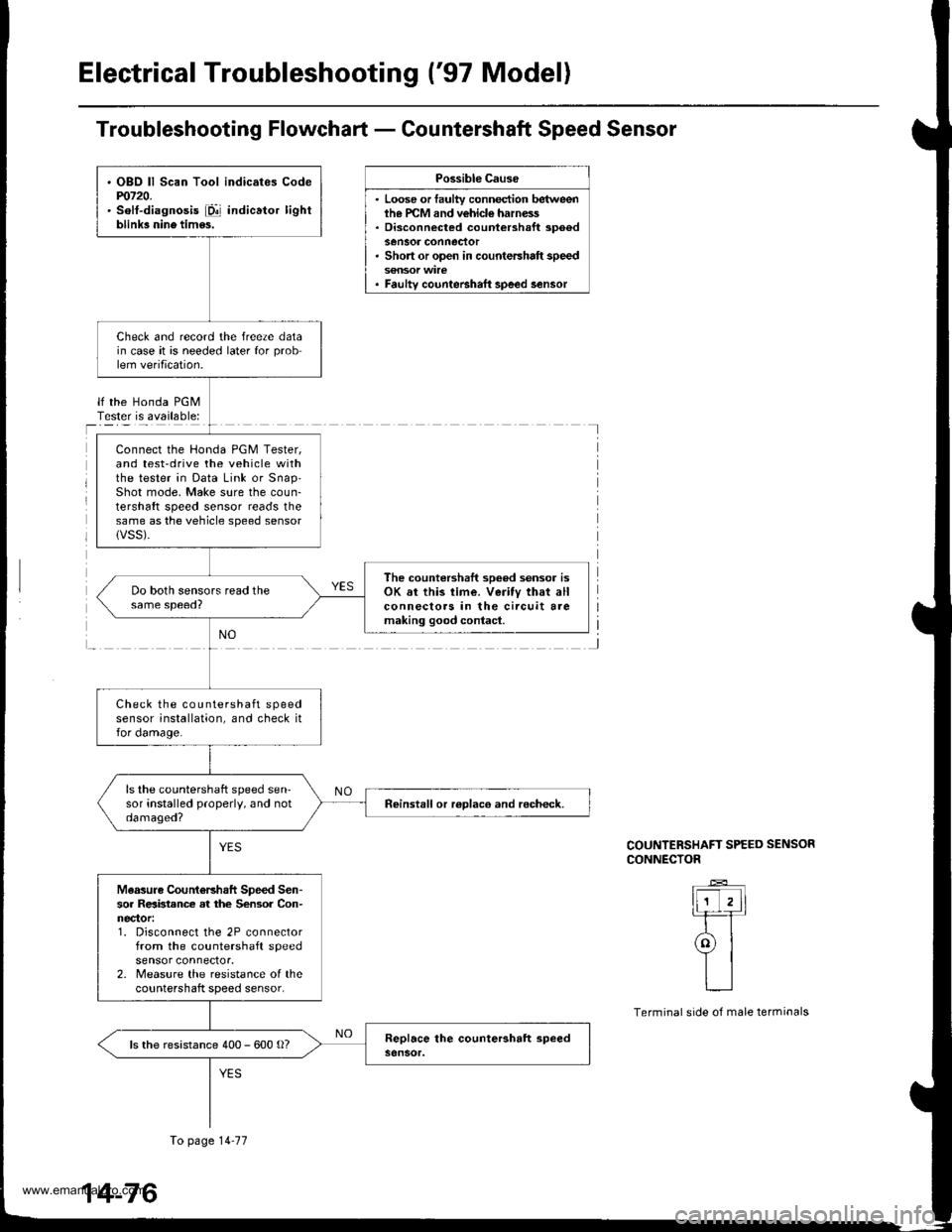
Troubleshooting Flowchart - Countershaft Speed Sensor
Possible Cause
. Loose or faulty connection betweenih€ PCM and vehicle harness. Disconnected countershaft spoedsensor conneclor. Short or open in countershaft speed
. Faulty counteBhaft speed lensor
lf the Honda PGMTester is available:I
J
COUNTERSHAFT SPEED SENSOR
CONNECTOR
ll-'T,ll-rT
ral
YIL__l
Terminal side of male terminals
. OBO ll Scan Tool indicates Codem720.' solt-diagnosis iD!' indicator lightblink3 nine tim6s.
Check and record the freeze datain case it is needed later for problem verification.
Connect the Honda PGM Tester,and test-drive the vehicle withthe tester in Data Link or snap'Shot mode, Make sure the coun-tershaft speed sensor reads thesame as the vehicle speed sensorlVSS).
The countershaft sooed sensor isOK sr this time. Veritv that allconnecloas in the circuit aremaking good contacl.
Check the countershaft speedsensor installation, and check itfor damage.
ls the countershaft speed sen-sor installed properly, and notdamaged?neinstall or roDlaco and recheck.
Measuro CountoBhaft Speed Sen-sor Relbtance at the Sensor Con-nector:1. Disconnect the 2P connectorfrom the countershaft speedsensor connector.2. Measure the resistance of thecountershaft speed sensor.
ls the resistance 400 - 600 o?
To page 14-77
14-76
www.emanualpro.com
Page 685 of 1395

Transmission
Removal
@
2.
'1.
Make sure lifts. iacks, and safety stands aro placed
properly, and hoist brackets are attached to the col-
rest position on the engine lsee section 11.
Apply th€ parking brake and block the r€ar wheels,
so vehicls will noi roll off the stands and fall on you
while working under it.
NOTE: Use fender covers to avoid damaging painted
surfaces.
Disconnect the negative terminal, then disconnect
the positive terminal from the battery.
Remove the intake air duct and the air cleaner hous-
ing assembly,
Remove the starter cables. Remove the harness
clamp from the clamp bracket.
5.
STARTERCABLES
Remove the transmission ground cable terminal
and the radiator hose clamp lrom the transmission
hanger.
Disconnect the lock-up control solenoid valve con-
nector, then remove the harness clamp from the
clamp bracket.HARNESS CLAMP
RADIATOR HOSECLAMP
CONTROLSOLENOID VALVECONNECTOR
CLAMP
6. Disconnect the vehicle speed sensor (VSS), the coun-
tershaft speed sensor, and the A/T gear position
switch connectors.
A/T GEAR POSITIONSWITCH CONNECTOR
VEHICLE SPEEDSENSOR |VSS'
CONNECTORBfiACKET
SPEED SENSORCONNECTOR
7. Remove the transmission housing mounting bolts.
MOUNTING BOLTS
(cont'd)
14-169
www.emanualpro.com
Page 691 of 1395
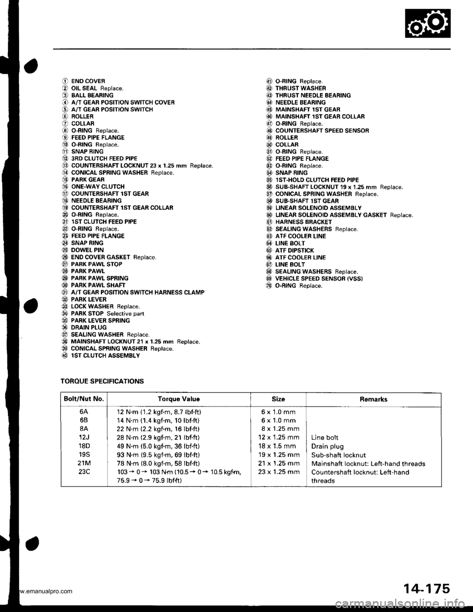
O END COVER
O olL SEAL Replace.
O BALL BEARING
@ A/T GEAR PoSITIoN swITcH coVER
€) A/T GEAn PosrloN swrrcH
@ ROLLER
O coLLARG) o-RING Replace.{9) FEED PIPE FLANGE
@ O-RING Replace.
O SNAP RING
@ 3RD CLUTCH FEED PIPE(D CoUNTERSHAFT LOCKNUT 23 x 1.25 mm Replace.(} coNtcAL SPR|NG WASHER Reptace.
@ PARK GEAR@ ONE.WAY CLUTCH(, COUNTENSHAFT lST GEAR(D NEEOLE BEARING(O COUNTERSHAFT lST GEAR COLLAR
@ o-RING Reptace.
@ lST CLUTCH FEED PIPE
@ O-RING Reptace.
@} FEEO PIPE FLANGE
@ SNAP RING
@ DOWEL PIN
@ END coVER GASKET Feplace.
@ PARK PAWL SToP@ PARK PAWL
@ PARK PAWL SPRING
@ PARK PAWL SHAFT
O} A/T GEAR POSITION SWITCH HARNESS CLAMP
@ PARK LEVER
@ LOCK WASHER Replace.
@ PARK STOP Selective part
@ PARK LEVER SPRING@ DRAIN PLUG
O SEALING WASHER Reptace.
@) MAINSHAFT LOCKNUT2l x 1.25 mm Replace.@ CONICAL SPRING WASHER Replace.@ lST CLUTCH ASSEMBLY
TOROUE SPECIFICATIONS
i!, O-RING Replace.
@ THRUST WASHER
@ THRUST NEEDLE BEARING@ NEEDLE BEARING
@ MAINSHAFI 1ST GEAR@ MAINSHAFT 1sT GEAR coLLAR
@ o-RING Replace.
6!, COUNTERSHAFT SPEED SENSOR@ ROLLER
@) COLLAR@ o-RtNG Replace.
6A FEEo PIPE FLANGE
@ o-RtNG Reptace.
@ SNAP R|NG
@ IST.HOLD cLUTcH FEED PIPE@ SUB-SHAFT LOCKNUT 19 x 1,25 mm Reptace.O coNtCAL SPR|NG WASHER Reptace.E! SUB.SHAFT lST GEAR€} LINEAR SOLENOID ASSEMBLY
@ LTNEAR soLENotD aSSEMBLy GASKET Reptace.
@ HARNESS BBACKET
@ SEALING WASHERS Feptace.
@ ATF COOLER LINE
@ LIN€ BoLT
@ ATF DIPSTICK
@ ATF COOLER LINE
@ LINE BoLT@ SEALING WASHERS Reptace.@ VEHICLE SPEED sENsoR (vss)
@ o-RtNG Beptace.
Bolt/Nut No.Torque ValuoSizeRemarks
6B
8A
12J
18D
19S
21M
23C
'12 N'm ('1.2 kgf.m,8.7 lbf.ft)
14 N.m (1.4 kgf.m, 10lb{.ft}
22 N.m 12.2 kgf.m, 16 lbf.ft)
28 N'm (2.9 kgf.m,21 lbf.ft)
49 N.m (5.0 kgf.m,36 lbf'ft)
93 N'm {9,5 ksim.69 lbf.ft)
78 N.m {8.0 kgnm,58 lbf.ft)
103* 0- 103 N{n {10.5* 0+ 10.5 kgfn,
75.9-0-75.9 lbf{t)
6x 1.0 mm
6x1.0mm
8 x 1.25 mm
12 x 1.25 mm
18 x 1.5 mm
19 x 1.25 mm
21 x 1.25 mm
23 x 1.25 mm
Line bolt
Drain plug
Sub-shaft locknut
Mainshaft locknut: Left-hand threads
Countershaft locknut: Left-hand
threads
14-175
www.emanualpro.com
Page 697 of 1395
![HONDA CR-V 1998 RD1-RD3 / 1.G User Guide
O END COVERiLl OIL SEAL Beplace.
O BALL BEARINGi.) A/T GEAR POSITION SWITCH COVER
i5] A/T GEAR POSITION SWITCH
aq) RoLLER
? COLLABi0 o-BtNG Replace.
€) FEED PIPE FLANGE
f,o) o-RING Replace.
1 SNAP HONDA CR-V 1998 RD1-RD3 / 1.G User Guide
O END COVERiLl OIL SEAL Beplace.
O BALL BEARINGi.) A/T GEAR POSITION SWITCH COVER
i5] A/T GEAR POSITION SWITCH
aq) RoLLER
? COLLABi0 o-BtNG Replace.
€) FEED PIPE FLANGE
f,o) o-RING Replace.
1 SNAP](/img/13/5778/w960_5778-696.png)
O END COVERiLl OIL SEAL Beplace.
O BALL BEARINGi.) A/T GEAR POSITION SWITCH COVER
i5] A/T GEAR POSITION SWITCH
aq) RoLLER
? COLLABi0 o-BtNG Replace.
€) FEED PIPE FLANGE
f,o) o-RING Replace.
1' SNAP RING
1A 3RD CLUTCH FEED PIPE
O COUNTERSHAFT LOCKNUT 23 x 1.25 mm Replace.
[} coNtcal SPRING WASHER Replace.iO PARK GEAR(!I ONE.WAY CLUTCH
E COUNTERSHAFT lST GEAR
@ NEEDLE BEARING
@ COUNTERSHAFT 1ST GEAR COLLAR
Or o-RtNGS Reptace.
?] lST CLUTCH FEED PIPE
@ o-RING Replace.
e3 FEED PIPE FLANGE
4I SNAP RING
€i DOWEL PINi?0 END COVER GASKET Replace.
?7) PARK PAWL STOP
E9 PARK PAWL
C9 PARK PAWL SPRING
€D PARK PAWL SHAFT
OI A/T GEAR POSITION SWITCH HARNESS CIAMP
@ PARK LEVER
€3 LoCK WASHER Replace.
04 PARK sToP Selective part(!' PARK LEVER SPRING
@ DRAIN PLUG
Ot SEALING WASHER Replace.
60 MA|NSHAFT LocKNuT 21 x 1.25 mm Replace.(9 CONICAL SPRING WASHER Replace.
@ lST CLUTCH ASSEMBLY
TOROUE SPECIFICATIONS
,!4! O-RING Replace.
@I THRUST WASHER@ THRUST NEEDLE BEARINGi.!' NEEDLE BEARINGi MAINSHAFT lST GEAR
@i MAINSHAFT 1ST GEAR COLLAR!r, O-RING Replace.iO COUNTERSHAFT SPEED SENSOR
E ROLLER
@, coLLAR
Ct o-RING Replace.5.] FEED PIPE FLANGE
09 o-RING Replace.
6A SNAP RING
5' IST.HOLD CLUTCH FEED PIPE
@-] SUB-SHAFT LOCKNUT 19 x 1.25 mm Replace.
!t CONICAL SPRING WASHER Replace.
6i' SUB-SHAFT lST GEAR
G) LINEAR SOLENOID ASSEMBLY(6!) LINEAR SOLENOID ASSEMBLY GASKET Replace
G] HARNESS BRACKET
6a SEALING WASHERS Replace.
C' ATF COOLER LINE
@ L|NE BoLT
GI ATF DIPSTICK
GI ATF COOLER LINE
O LINE BOLT
@ SEALING wasHERs Replace.aoo VEHICI.E SPEED SENSOR IVSS)
f,E O-RING Replace.
Bolt/Nut No.Torque ValueSizeRemarks
6A
6B
8A
12J'18D
195
21M
12 N.m (1.2 kgf.m,8.7 lbf.ft)
14 N.m (1.4 kgf.m, 10lbf.ft)
22 N.m 12.2 kgim, 16lbf.ft)
28 N.m (2.9 kgim,21 lbf.ft)
49 N'm (5.0 kgim,36 lbf.ft)
93 N.m (9.5 kgf.m,69 lbf.ft)
78 N.m (8.0 kgf.m,58 lbf.ft)
103+ 0+ 103 N{n (10.5 + 0+ 10.5 kSfm,
75.9' 0 - 75.9 lbfft)
6x1.0mm
6x1.0mm
8 x 1.25 mm
12 x 1 .25 mm
18 x 1.5 mm
19 x 1.25 mm
21 x 1.25 mm
23 x 1.25 mm
Line bolt
Drain plug
Sub-shaft locknut
Mainshaft locknut: Left-hand threads
Countershaft locknut: Left-hand
threads
14-181
www.emanualpro.com
Page 779 of 1395

26. Connect the vehicle speed sensor (VSS). the coun-
tershaft speed sensor. and the A,/T gear position
switch connectors,
VEHICLE SPEEO
SPEED SENSOACO'{NECTOR
Connect the lock-up control solenoid valve connec-
tor, then install the harness clamp on the clamp
bracket.
HARNESS CI-AMP
27.
RADIATOR HOSECLAMP
TRANSMISSIONGROUND CAB1ITERMINAL
LOCK-UP OONTROLSOLENOID VALVECONNECTOR
6x1.0mm12 N'm (1.2 kgi.m,8.? tbtftl
28.
29.
Instail the transmission ground cable terminal on
the transmission hanger, and install the radiator
hose clamp on the transmission hanger,
Connect the starter cables to the starter, and install
the harness clamD on the clamD bracket. Make sure
the crimped side of the starter cable ring terminal is
facing out.
STARTEBCABLE
STARTER CAAtf,
Install the air cleaner housing assembly and the
intake air duct.
Refill the transmission with ATF (see page 14-161).
Connect the battery positive terminal and negative
terminal.
Set the parking brake, Start the engine, and shift the
transmission through all gears three times.
Check the shift cable adjustment (see page 14-271]-.
Check the tront wheel alignment and adjust it if
needed (see section 18).
Let the engine reach normal operating temperature
(the radiator fan comes on) with the transmission in
E or N position, then turn it off and check the ATF
level {see page 14-160).
Perform a road test (see page 14-157 and 14-158).
30.
31.
34.
CLAMP BRACKET
37.
14-263
www.emanualpro.com