clutch system HONDA CR-V 1998 RD1-RD3 / 1.G User Guide
[x] Cancel search | Manufacturer: HONDA, Model Year: 1998, Model line: CR-V, Model: HONDA CR-V 1998 RD1-RD3 / 1.GPages: 1395, PDF Size: 35.62 MB
Page 358 of 1395
ldle Gontrol System
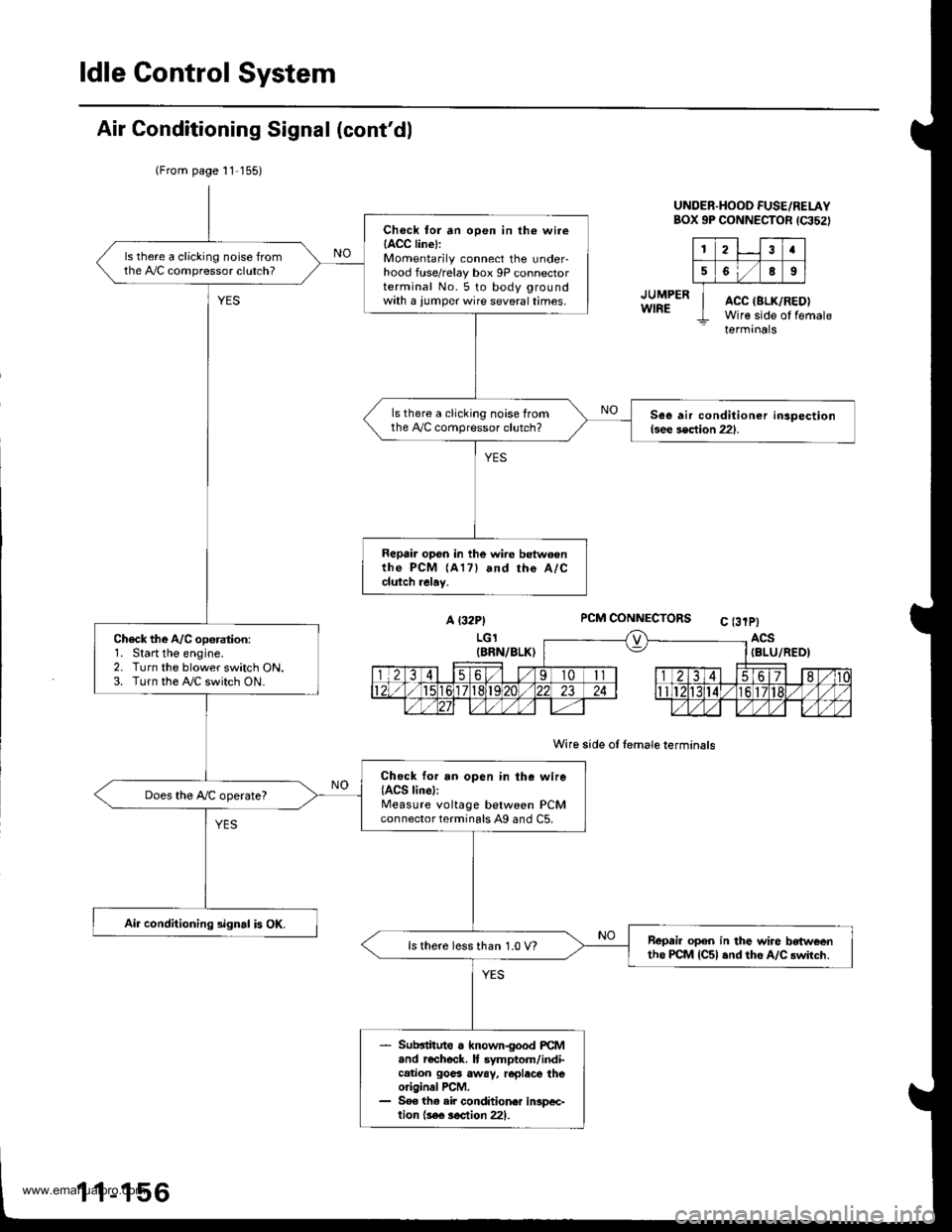
Air Conditioning Signal (cont'dl
(From page 11-'155)
JUMPERWIRE
UNOER.HOOD FUSE/RELAYBOX 9P CONNECTOR tqt52)
123I
56I
ACC IBLK/RWire side ofACC IBLK/REDIWire side of femaletermrnats
A t32PlPCM CONNECTORS C t3rp)
Wire side ol lemale terminals
Ch6ck for an open in th€ wire(ACC linel:Momentarily connect the under-hood fuse/relay box 9P connectorterminal No.5 to body groundwith a jumper wire several times.
ls there a cl;cking noise fromthe 4!/C compressor clutch?
ls there a clicking noise fromthe 4!/C compressor clutch?See air condiiioner inspection{see section 221.
Repai. op6n in the wire betwoenthe PcM (A17) and tho A/Cclutch relay.
Check the A/C operation:1. Start the engine.2. Turn the blower switch ON.3. Turn the A"/C switch ON.
Check for an open in the wire(ACS line):Measure voltage between PCMconnector terminals Ag and C5.
Does the A,/C operate?
Air conditioning signal is OK.
Repair open in the wire betweenthe PCM lCSl and the A/C awitch.ls there less than 1.0 V?
- Subqtitute a known-good FCM.nd r€ch6ck. lt 3ymptom/indi-cation goes awav, replece theoriginal rcM.- Soe th€ eir conditioner in3pec-tion (s6€ aec.tion 22).
www.emanualpro.com
Page 360 of 1395
ldle Control System
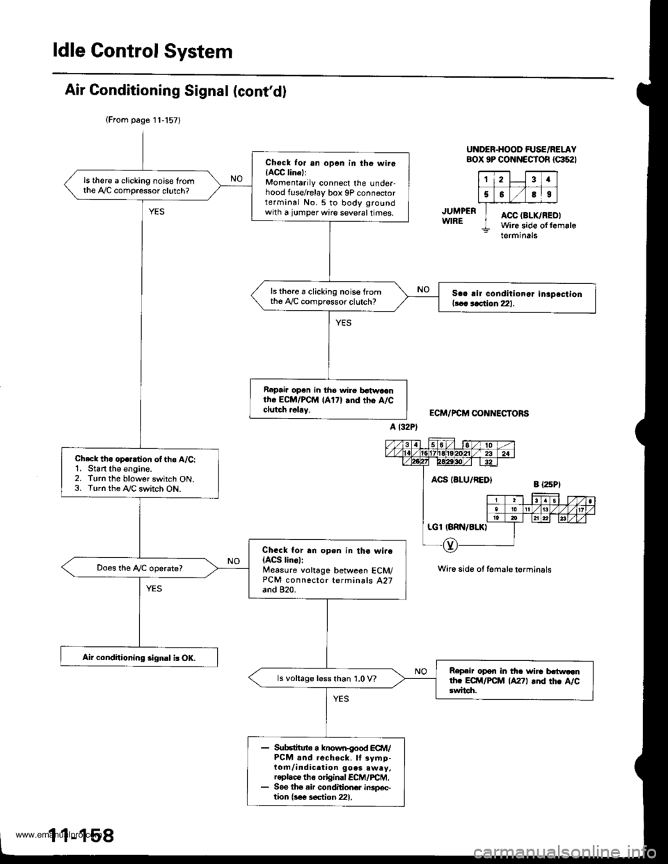
Air Gonditioning Signal (cont'd)
JUMPERWIRE
UNDER-HOOD FUSE/RELAYBOX 9P CONNECTOR {G'52I
23a
5589
ACC (BLK/R
Wire side otACC (BLK/RED'
Wire side otfemaleterminals
ECM/PCM CONNECTORS
Wire sid€ of female torminals
(From page '11,157)
Check Ior dn opon in the wiroIACC linel:Momentarily connect the under-hood fuse/relay box 9P connectorterminal No. 5 to body groundwith a jumper wire several times.
ls there a clicking noise lromthe y'y'C compressor clutch?
ls there a clicking noise fromtho A,/C comprossor clutch?Sae rir conditional in3pactionlroa saction 221.
Repai. open in th6 wiro lr€twlanthe ECM/PCM lAl7l .nd tho A/Cclutch rolay.
Check tho op.ration of tho A/C:1. Stan the engine.2. Turn the blower switch ON.3. Turn the Ay'C switch ON.
ChGGk for an open in the wi.eIACS linel:Measure voltage betweon ECM/PCM connector terminals A27and 820.
Does the !y'C operate?
Air conditioning 3ignal i3 OK.
Rap.ir opon in the wir6 bdtunaanrh. Ecil/FcM lA27l rnd rh. A/crwitch.
ls voltage less than 1.0 V?
Sub6lftna a known{ood ECM/PCM and rechock. lf symp-tom/indicetion goes away.roplace the original ECM/rcM.See the ah conditionor inspoc-tion {3e€ section 22},
www.emanualpro.com
Page 390 of 1395
![HONDA CR-V 1998 RD1-RD3 / 1.G User Guide
Fuel Supply System
PGM-FI Main Relay (contdl
Troubleshooting
lc(}21PGM.FI MAIN RELAY 7P CONNECTOR
GND
trTr]--Flq
FI,TilI A
Y
Wire side ot female terminals
- Engine will not start.- InsDection ol PG HONDA CR-V 1998 RD1-RD3 / 1.G User Guide
Fuel Supply System
PGM-FI Main Relay (contdl
Troubleshooting
lc(}21PGM.FI MAIN RELAY 7P CONNECTOR
GND
trTr]--Flq
FI,TilI A
Y
Wire side ot female terminals
- Engine will not start.- InsDection ol PG](/img/13/5778/w960_5778-389.png)
Fuel Supply System
PGM-FI Main Relay (cont'dl
Troubleshooting
lc(}21PGM.FI MAIN RELAY 7P CONNECTOR
GND
trTr]--Flq
FI,Til'I A
Y
Wire side ot female terminals
- Engine will not start.- InsDection ol PGM-FI mainrelay and relay harness,
Check fo. an open in the wireIGND linol:1. Turn the ignition switch OFF.2. Disconnect the PGM Fl mainrelay 7P connector.3. Check for continuity betweenthe PGM'FI main relay 7P con-nector terminal No. 3 and bodyground.
Repair opcn in th€ wire betweenthe PGM-FI main relav and G101.
Check tor an open or short in thewiro (BAT line):Measure voltage between thePGM'FI main relay 7P connectorterminal No. 7 and body ground.- Repai. open or short in lhewir6 belween the PGM-FImain relay and the Fl E/M (15Al fu3e.- Replace th6 FIE/M (15 Altus6in th€ under-hood fuse/.6lay
ls there baftery voltage?
Check lor an open or short in thewire (lGl line):L Turn the ignition switch ON (ll).2. Measure the voltage betweenthe PGM-FI main relay 7P connectorterminal No. 5 and bodyground.- Repair open or shorl in thewire between the FGM-FI mainrelay and the No. 13 FUELPUMP 115 A) tuse.- Replaco the No. 13 RJEL PUMP115 A) luse in the und6.-d$hfuso/ relav box.Check for an open or short in thewire {STS line):1. Turn the ignition switch to theSTART (lll) position.NOTE:. M/T: Clutch pedal must bedepressed.. A/T: Transmission in E orElposition.2. Measure the voltage betweenthe PGM-Fl main retay 7Pconnector terminal No. 2 andbody ground.- Repair open or short in thewire betwe€n the PIGM-FI m.inrclay and th€ No. 31 STARTERSlGllAL 17.5 A) tuse.- Repl.ce the No. 31 STARTERSIGNAL 17.5 Al tuse in theunder-dash tuse/relay box.('97 model: To page 11-189)('98 00models:To page 1l 190)
1 1-188
www.emanualpro.com
Page 430 of 1395
lllustrated Index
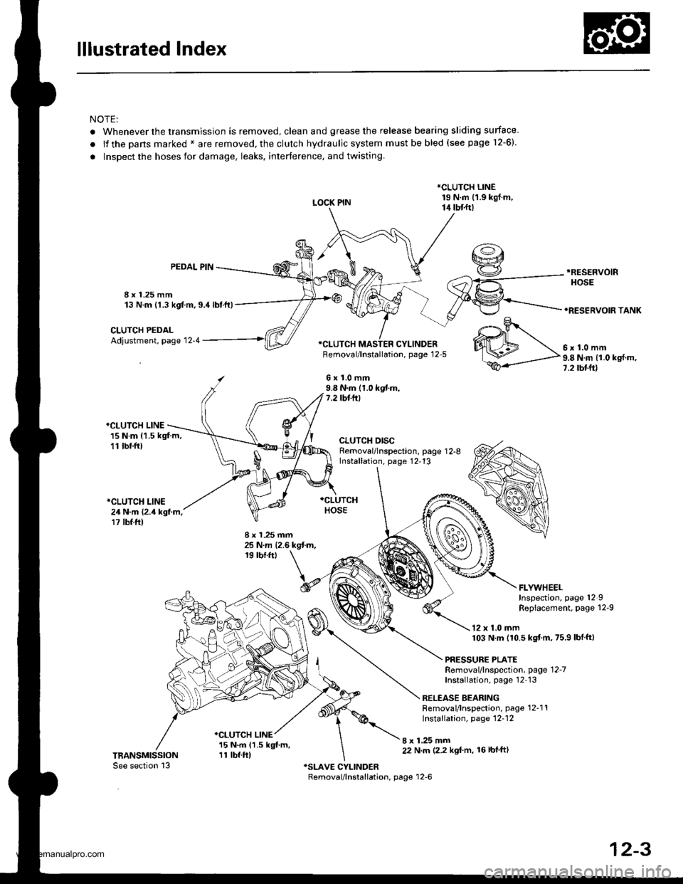
NOTE:
. Whenever the transmission is removed, clean and grease the release bearing sliding surface
.lfthepansmarked*areremoved,theclutchhydraulicsystemmustbebled(seepage1\
2-6).
. Inspect the hoses for damage. leaks. interference, and twisting.
LOCK PIN
*CLUTCH LINE19 N.m (1.9 kgj.m,14 tbtft)
8 x 1.25 mm13 N.m {1.3 kgf m,9.4lbtft)
PEDAL PIN.RESEFVOIR
HOSE
*RESERVOIR TANK
CLUTCH PEDALAdjustment, page 12-4*CI-UTCH MASTER CYLINDERFemoval/lnstallation, page 12-5
6x1.0mm9.8 N.m (1.0 kgf.m,7.2 tbf.ft)
*CLUTCH LINE15 N.m (1.5 kgt m,11 tbr.ft)
*CLUTCH LINE24 N.m {2.4 kgf.m,17 tbf.ft)
CLUTCH DISCRemoval/lnspection, page 1 2-8Installation, page 12,13
8 x 1.25 mm25 N.m {2.6 kgt m,19 rbf.ftt
I x 1.25 mm22 N.m 12.2 kgl'm, 16lbfft)
.o-.9r
WM\,".0--
ffi-P"8Nmlloks{m'
FLYWHEELInspection, page 12IRepiacement, page 12-9
12 x 1.0 mm103 N.m (10.5 kgtm,75.9 lbf ftl
PRESSURE PLATERemoval/lnspection, page'12-7
Installation, page'12 13
RELEASE BEARINGRemoval/lnspection, page 12-1'!Installation, page 12-12
*CLUTCH LINE15 N.m (1.5 kgt m,11 tbf.ft)
12-3
www.emanualpro.com
Page 432 of 1395
Glutch Master Cylinder
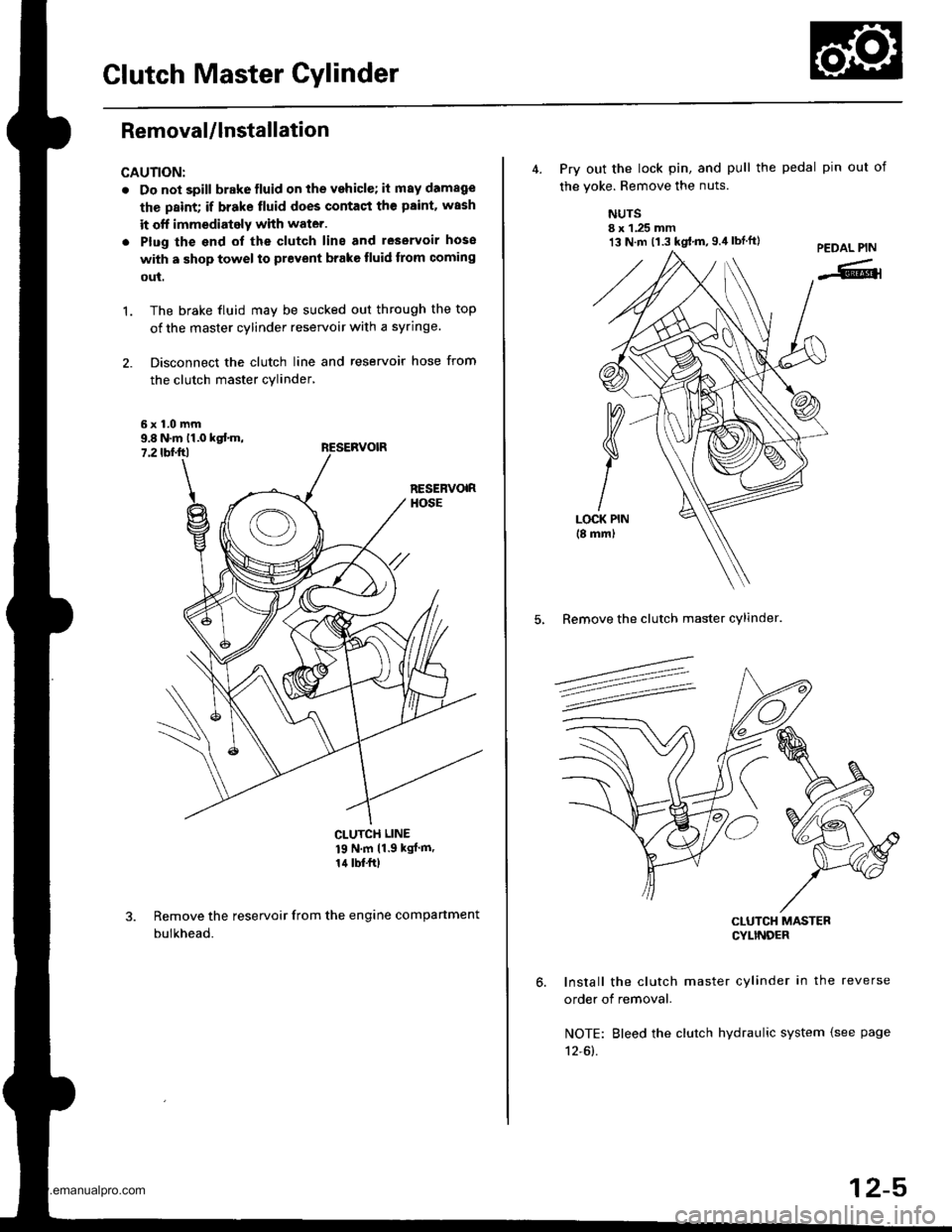
Removal/lnstallation
CAUTION:
. Do not spill brake fluid on the vehicle; it may damage
the paint; if brake tluid does contact the paint. wash
it off immediately with water.
. Plug the end ol the clutch line and leservoir hose
with a shop towel to prevent brake tluid trom coming
out.
The brake fluid may be sucked out through the top
of the master cylinder reservoir with a syringe.
Disconnect the clutch line and reservoir hose from
the clutch master cylinder,
't.
9.8 N.m 11.0 kst m,7.2 tbf.ftl
CLUTCH LINE
19 N'm 11 9 kgJ m'
14 lbf.frl
Remove the reservoir from the engine compartment
bulkhead.
13 N.m t1.3 kgt.m,g.il lbtft)
4. Prv out the lock pin, and pull the pedal pin out of
the voke. Remove the nuts.
NUTSI x 1.25 mm
5, Remove the clutch master cylinder.
CLUTCH MASTERCYLINDEF
Install the clutch master cylinder in the reverse
order of removal.
NOTE: Bleed the clutch hydraulic system {see page
12-61.
12-5
www.emanualpro.com
Page 433 of 1395
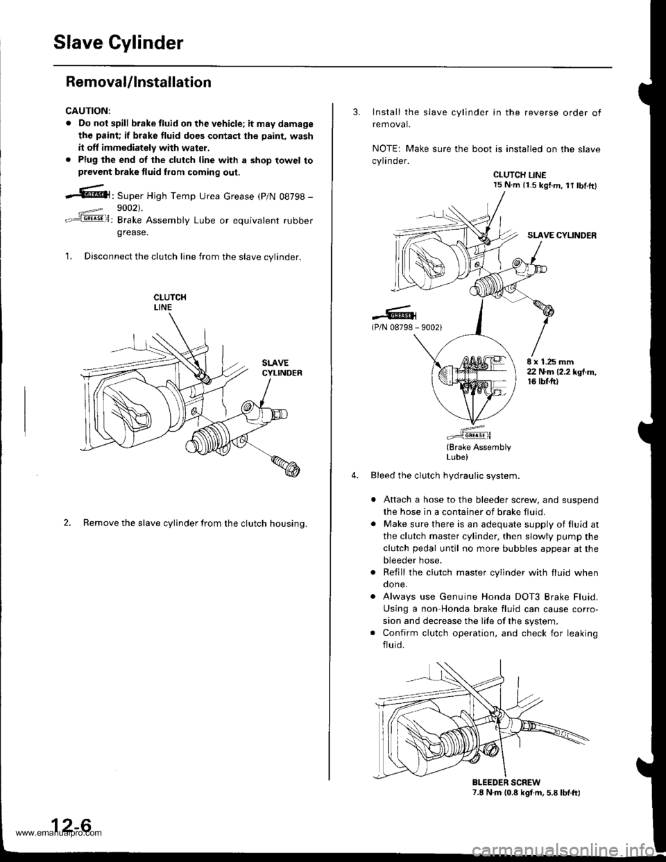
Slave Cylinder
RemovaUlnstallation
CAUTION:
. Do nol spill brake tluid on the vehicle; itmaydamage
the paint; if brake fluid do€s contast the paint, wash
it off immediately with water.. Plug the end of the clutch line with a shop towel toprevcnt brake tluid from coming out.
.6|l,Super High Temp Urea crease (p/N 08798 -
9002).
: Brake Assembly Lube or equivalent rubber
grease.
1. Disconnect the clutch line from the slave cvlinder.
2. Remove the slave cylinder from the clutch housing.
12-6
3. Install the slave cylinder in the reverse order ot
removal.
NOTEr Make sure the boot is installed on the slave
cylinder.
CLUTCH LINE15 N.m (i.S kgf.m, lt tbf.ftl
SLAVE CYLINDER
.-lG(P/N 08798 - 90021
E x 1.25 mm22 N.m (2.2 kgt.m,16 tbtft)
(Brake AssemblyLube)
Bleed the clutch hydraulic system.
Attach a hose to the bleeder screw, and suspend
the hose in a container of brake fluid.
Make sure there is an adequate supply of fluid at
the clutch master cylinder, then slowly pump the
clutch pedal until no more bubbles appear at the
bleeder hose.
Refill the clutch master cylinder with fluid whenqone.
Always use Genuine Honda DOT3 Brake Fluid.
Using a non Honda brake fluid can cause corro-
sion and decrease the life of the system.
Confirm clutch operation, and check for leaking
fluid.
7.8 N.m (0.8 kgf.m. 5.8 lbt.ft)BLEEDER SCREW
www.emanualpro.com
Page 517 of 1395

Automatic Transmission
Special Tools . 14'2OescriptionGeneral Operation . .... 14 3Power Flow . . .. '14_6
Electronic Control System .. .. . . .. .14_15Hydraulic Control .. 14 24Hydraulic Flow....-....... .. . .... .. .. . 14_29Lock'up Syslem .. .'t4'39Electrical SystemComponenl Locdlrons 14 45
PCM Circuil Dragram (A/T Control Svstem)'97 Model ....................... . . .. - . ... .14-46'98Model ................. . ... .. .. .1450'99 00Models.... . .... . . . 1452
PCM Terminal Voltage/Measuring ConditionsA"/T Control System-'97Model ...... ..14'48A,/T Control System -'98 00 Models . . .. . . 14 54
Troubleshooting Procedures .. ..... ... - 14_56Svmotom to comoonent CharlEiectr,cal Syslem -'97 Model . . 14 60Electrical System -'98 - OO Models . .. . . 14_62Electrical Troubleshooting ('97 Model)Troubleshooting Flowaharts .... ..... . .. . . 14_64
Electrical Troubleshooting ('98 - 00 Models)Troubleshootinq Flowclt"n" .... . ....- . .14-93ElectricalTroublesliooting('99 00Models)Troubleshootino FlowchartO/D OFF Indicator Light Does Not Come On 14 131
O/D OFF Indicator Liaht On ConstantlY . . . .1!-132O/D OFF Indicator Light Does Not Come OnEven Though O/D Switch ls Pressed . .... - 14_133
Lock up Control Solenoid Valve A,/B AssemblyTest....................-......... . .14-135Replacement . .ll_135Shifr ControlSolenoid Valve Ay'B Assembl,Test .............................. . .. 14-136
Replacement..............- . .14'136Linear Solenoid AssemblYTest.............................................. .. .... . 14_137Replacement .. . 14138Marnshaftlcountershafl Speed SensorsReplacement ...-... 14_138A/T Gear Position SwitchTest ..........................-... . .. 14-139ReplacementA/T Gear Positionlndicator.................. 14-140
Valve Eodynepair ............................... ..... . . .. - . .. ... 14 192
Assembly .................... .. 1{_193
Valve CapsDesciiption....-........................ .. ...... 14194
tnspeition ................... .. 14' 195
N4ain Valve BodyDisassembly/lnspection/Reassemblv - ...... .. 14_196
Secondarv Valve BodYDisassemblv4nspectron/ReassemblY .. . 14 198
Reoulator Valve Bodvbisassembtv,lnspiction/Reassemblv . 14199
Servo EodvDisassembly/lnspection/Reassembly ... ....14'200
Lock'uo Valve BodYDis;ssembly/lnspection/Reassembly .... . 14_201
MainshaftDisassembly/lnspection/Reassembly .. .. .. ..14'202
Inspection ....-.............. ..11_203
Sealing RingsReilaceient ...... ..... . 14'204
CountershaftDisassembly/lnspection/Reassembly .. . . . . . 11-205
Disassembly/Reassemb|y . . ........ ...... . .. 14_206Inspedron ................ . .... . 14 207
One wav ClutchDisassembly/lnspection/ReassemblY ... 11_209
Sub-shaftDisassembly/lnspection/Reassembly ... . .. . 14-210
oisassembly/Re6ssembly . . ... .-...... . . ..14-211
Sub-shaft BearingsReplacement .......14'212
Clutchllfustrated Index .......... . . .14-213
Disassembly .... .. .....14-216Reassembfy .... . .. .. . 14'218
Differentialllfustrated Index " 14-222Backlash Inspection . .... . .14'223
Bearing Repiacement .. 11-223
Differe-ntial Carrier Replacement .. .. . . . .. ..11-2?4
OifSeal Replacement. . .. 14'225
Side Clearance lnspection . . - .. ... . - ...... . .. 11'226
Transmission Housing BearingsMainshaJVCountershaft EearingsRepfacement .......14221Sub'siralt Eearing Replacement . . . . . . . . . ..11'224
Toroue Converter Housing BearingsMainshattEearing/OilSe6lReplacement . .. l4229
Countershaft Bea;ing Replacement.. .... .. ..14-230
Input Test - '97 - 98 ModelsInput Test '99 - 00 Models
Symptom to-Component ChartHydraulic System ...............
Checking
Removal ...,lllustrated Index (4WD)
Interlock SystemInterlock ControlUnit lnputTest. -..... -.. .... . - 14 144* Key Interlock Solenoid Test .- .. . . . - . . . ..... 14_146* Shift Lock Solenoid Test ..............-.-. . .. . ... .... 14 147*Shift LockSolenoidReplacement...... .. . .. .. 14 148* park pin Switch Test ......... 14 119' Park Pin Switch Replacement- '97 - 98 Models ....... 14-150* Park Pin Swirch/Over Drive (O/Di SwitchReplacemenl '99-00Models . .. 14_151over-Drive (O/D) Switch {'99 00 [4odels]Test........_..................... .......14-152Hydr.ulic System
..............._............... t4 142.................................. 14-143
Control Lever AssemblyR6placement ......,.,Reverse ldler Gear
lllustrated lndex
.......... 14-230
14 231
11-231
1nsta1|ation ..................Park StopInspeclion/AdjustmenlTransfer AssemblY.......14.232
RoadTest.............-.... ........ .StallSpeedTest ....._........................ ....... 14-159Fluid Level......_................... 14'160
Disessembly .................... 14-235Transfer Drive Gear BearingReplacementTrans{er Driven Gesf Shaft BearingReplacementTransfer Housing Roller BearingReplacementTransfer Cov€r A Bearing Outer RaceReplacementTransfer Housing Bearing Outer RaceReplacement ......-..,,,,,.....ReassemblvTransmassaonBeassembly ... -.. .... .14 250
Torque Converier/Drive Plate . .-. .... .. . ... .....14_258
Transmissionlnstatlation .................. ....... 14'259
Cooler Flushing . . ......11-261ATF Cooler HosesConnection.................. ....... 14-266I Shift LeverRemoval/lnstallation . .. 14'261
Disassemblv/Reassemblv - '97 - 98 Models . . 14_264
Disassembli/Reassemblv -'99 - 00 Models . 14-269
Over'Orive (O/D) Switch WireClearanceAdjustment. - ... . . . .. .. . 14'270
Detent Spring Replscement . . -.. ... .14'271*Shift CableAdiustment ....... 14'272
Repfacement.............. . 11'273
14 15711-237
11-237
14-238
$-234
11-23914-240
Transmigrion
Inspeclron ....., ...........Transfer AssemblyRemova1,.,,,..............,lnstallalion ........... .. ...Transmission
14 164
14-16514,167
14-169
End Cover/Transmissio . 14'174Transmission Housing .... ... .. . . .... .. 14-176Torque Converter Housingly'alve Body.. - ... -. 14 178
lllustrated lndex (2WD)End Cover/Transmissio ....... 14 180Transmission Housing . . ... . .. .... ... 14'182Torque Convener Housing/r'alve Body ......- 14-184
End CovefRemovat ...................... ....... 14'186Transmission HousingRemoval ...................... .. 14_188Torque Convener HousingA/alve BodYRemovat ................-..... .-..... 14-190
www.emanualpro.com
Page 519 of 1395

Description
General Operation
The Automatic transmission is a 3-element torque converter and triple-shaft electronically controlled unit which provides 4
speeds forward and 1 reverse speed The unit is positioned in line with the engine'
There are two tvoes of automatic transmission on CR-V; the four-wheel drive (4WD) model ('97 - 00)' and the front-wheel
drive (2WD) model ('98 - 00).
Toroue Converter, G€ars, and Clutches
The torque converter consists of a pump. turbine. and stator assembly in a single unit. The torque converter is connected to
the engine crankshatt. These parts turn together as a unit as the engine turns. Around the outside of the torque converter is
a ring gear which meshes with the starter pinion when the engine is started. The torque converter assembly serves as a fly-
wheel while transmitting power to the transmission mainshaft.
The transmission has three parallel shafts: the mainshaft. the countershaft, and the sub-shaft. The mainshaft is in line with
the engine crankshaft. The mainshaft includes the 1st, 2nd. and 4th clutches, and gears lor 3rd,2nd,4th. reverse and 1st
(3rd gear is integral with the mainshaft, while reverse gear is integral with the 4th gear). The countershaft includes the 3rd
clutch and gears for 3rd,2nd, 4th, reverse, 1st, and park. Reverse and 4th gears can be locked to the countershaft at its cen-
ter, providing 4th gear or reverse, depending on which way the selector is moved. The sub-shaft includes the lst-hold
clutch and gears for lst and 4th.
The gears on the mainshaft are in constant mesh with those on the countershaft and sub-shaft. When certain combinations
of gears are engaged by the ctutches, power is transmitted from the mainshaft to the countershaft to provide E, D!, tr, tr,
and E position ('97 - 98 models). and E. E, E, and E position ('99 - 00 models)'
Electlonic Control
The electronic controt system consists of the Powenrain Control Module (PCM), sensors, a linear solenoid, and four
solenoid valves. Shifting and lock-up are electronically controlled for comfortable driving under all conditions. The PCM is
located below the dashboard, under the kick panel on the passenger's side.
Hydraulic Control
The valve bodies include the main valve body, the secondary valve body, the regulator valve body, the servo body, and
the lock up valve body. They are bolted to the torque converter housing. The main valve body contains the manual valve,
the 1-2 shift valve, the 2nd orifice control valve. the CPB {Clutch Pressure Back-up) valve, the modulator valve, the servo
control valve. the relief valve, and ATF pump gears. The secondary valve body contains the 2-3 shift valve, the 3-4 shift
valve, the 3,4 orifice control valve. the 4th exhaust valve and the CPC (Clutch Pressure Control) valve. The regulator valve
bodv contains the pressure regulator valve, the torque converter check valve, the cooler relief valve, and the lock-up con-
trol valve. The servo body contains the servo valve which is integrated with the reverse shift tork, and the accumulators
The lock-up valve body contains the lock-up shift valve and the lock-up timing valve. The linear solenoid and the shift con-
trol solenoid valve Ay'B are bolted to the outside of the transmission housing, and the lock-up control solenoid valve Ay'B is
bolted to the outside of the torque converter housing. Fluid trom the regulator passes through the manual valve to the
various control valves. The clutches receive fluid from their respective feed pipes or internal hydraulic circuit
ShiftControl Mechanism
input from various sensors located throughout the vehicle determines which shift control solenoid valve the PCM will acti-
vate. Activating a shift control solenoid valve changes modulator pressure, causing a shift valve to move. This pressurizes
a line to one of the clutches. engaging that clutch and its corresponding gear. The shift control solenoid valves A and B are
controlled by the PCM.
Lock-up Mechanism
tn E! position (,97 - 98 modets) and in E position ('99 - O0 models), in 3rd and 4th, and in Del position in 3rd ('97 - 98
models) and in El position with Over,Drive (O/D) is OFF (by pressing rhe O/D switchl in 3rd ('99 - 00 models), pressurized
fluid is drained from the back of the torque converter through a fluid passage, causing the lock-up piston to be held
against the torque converter cover, As this takes place, the mainshaft rotates at the same speed as the engine crankshaft.
Together with hydraulic control, the PcM optimizes the timing of the lock-up mechanism The lock-up valves control the
range of lock-up according to lock-up control solenoid valves A and B, and the linear solenoid. When lock-up control
solenoid valves A and B activate, the modulator pressure changes. The lock-up control solenoid valves A and B and the
linear solenoid are controlled by the PCM.
{cont'd)
14-3
www.emanualpro.com
Page 540 of 1395
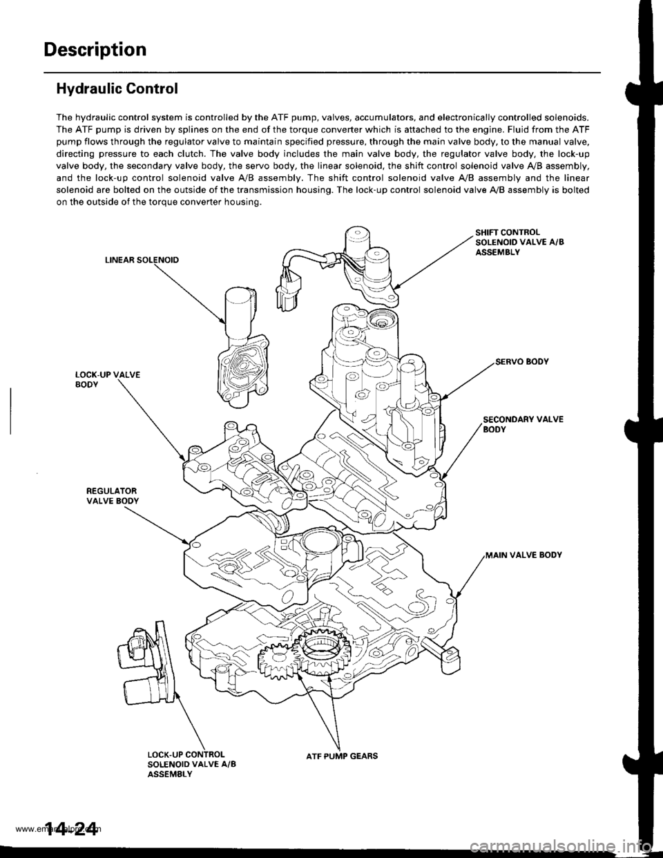
Description
Hydraulic Control
The hydraulic control system is controlled by the ATF pump, valves, accumulators, and electronically controlled solenoids.
The ATF pump is driven by splines on the end of the torque converter which is aftached to the engine. Fluid from the ATF
pump flows through the regulator valve to maintain specified pressure, through the main valve body, to the manual valve,
directing pressure to each clutch. The valve body includes the main valve body, the regulator valve body, the lock-up
valve body, the secondary valve body, the servo body, the linear solenoid, the shift control solenoid valve Ay'B assembly,
and the lock-up control solenoid valve A/B assembly. The shift control solenoid valve A,/B assembly and the linear
solenoid are bolted on the outside of the transmission housing. The lock-up control solenoid valve A,/B assembly is bolted
on the outside of the torque converter housing.
LINEAR
SHIFT CONTROLSOLENOID VALVE A/BASSEMBLY
SECONDARY VALVEBODY
REGULATORVALVE BOOY
VALVE BODY
SOLENOID VALVE A/BASSEMELY
N
ATF PUMP GEARS
14-24
www.emanualpro.com
Page 555 of 1395
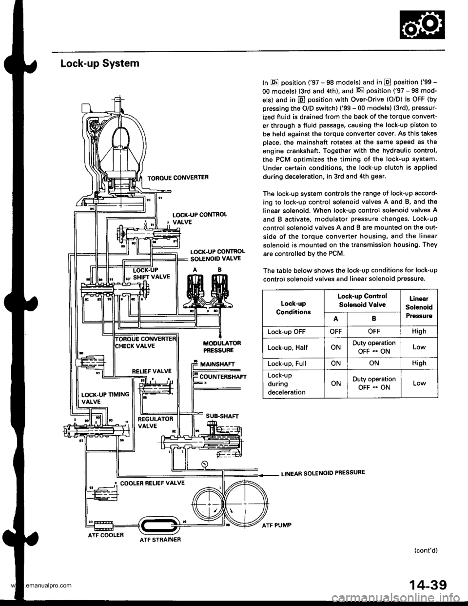
Lock-up System
TOROUE CONVERTER
In E position ('97 - 98 models) and in E position ('99 -
OO models) (3rd and 4th), and E position ('97 - 98 mod-
els) and in E position with Over-Drive (O/D) is OFF (by
pressing the O/D switch) ('99 - 00 models) (3rd), pressur-
ized fluid is drained from the back of the torque convert-
er through a fluid passage, causing the lock-up piston to
be held against the torque converter cover, As this takes
Dlace, the mainshaft rotates at the same speed as th8
engine crankshaft. Together with the hydraulic control,
the PCM optimizes the timing of the lock-up system.
Under certain condltions. the lock-up clutch is appli€d
during deceleration, in 3rd and 4th gear.
The lock-up system controls the range of lock-up sccord-
ing to lock-up control solenoid valves A and B, and ths
linear solenoid. When lock-up control solenoid valves A
and B activate. modulator pressure changes. Lock-up
control solenoid valves A and B are mounted on the out-
side of the torque converter housing, and the linear
solenoid is mounted on the transmission housing. They
are controlled bv the PCM.
The table below shows the lock-up conditions for lock-up
control solenoid valves and linear solenoid pressure.
LINEAR SOLENOID PRESSURE
(cont'd)
LOCK.UP CONTROL' VALVE
LOCK.UP CONTROLSOLENOID VALVE
AB
MODULATORPf,ESSURE
MAINSHAFT
COUNTERSHAFT
SUB.SHAFT
Lock-up
Conditions
Lock-up Conirol
Solenoid valveLinaal
Solenoid
PrgssulsAB
Lock-up OFFOFFOFFHigh
Lock-up, HalfONDuty operation
OFF - ONLow
Lock-up, FullONONHigh
Lock-up
during
deceleration
ONDuty operation
OFF - ON
RELIEF VALVE
LOCK'UP TIMINGVALVE
COOLER RELIEF VALVE
ATF COOLERATF STRAINER
ATF PUMP
14-39
www.emanualpro.com