Ac system HONDA CR-V 1998 RD1-RD3 / 1.G Workshop Manual
[x] Cancel search | Manufacturer: HONDA, Model Year: 1998, Model line: CR-V, Model: HONDA CR-V 1998 RD1-RD3 / 1.GPages: 1395, PDF Size: 35.62 MB
Page 645 of 1395
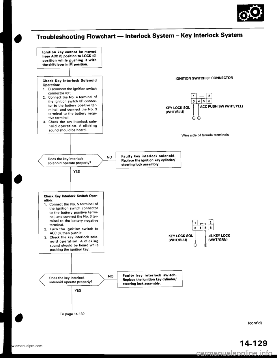
Troubleshooting Flowchart - Interlock system - Key Interlock system
IGNITION SWITCH 6P CONNECTOR
KEY LOCK SOL
IWHT/BLU)
ACC PUSH SW (WHT/YEL}
Wire side ot female terminals
KEY LOCK SOL
IWHT/BLUI
+B KEY LOCK(WHT/GRN)
(cont'd)
lgnition ksy cannot be moved
from ACC (l) pGition to LOCK (01
position while Pushing it with
the shift lever in E PGition.
Check Key lntorlock Solenoid
Operation:1. Disconnect the ignition switch
connector (6P).
2. Connect the No. 4 terminal of
the ignition switch 6P connec-tor to the battery Posative ter_minal, and connect the No. 3
terminal to the battery nega
tive terminal.3. Check the key interlock sole-no id operation. A clicking
sound should be heard.
F.ulty key interlock solenoid.
Replace tho ignition key cylinder/
steering lock asembly.
Does the key interlocksolenoid operate ProPerlY?
Ch€ck Key |motlock Switch OPer'etion:1. Connect the No. 5 terminal of
th€ ignition switch connectorto the battery Positive termi-nal, and connectthe No.3 teF
minal to the baftery negativetermrnal,2. TLrrn the ignition switch toACC (l), then PUsh it.3. Check the key interlock sole-noid operation. A clickingsound should be heard whilepushing the ignition kev.
Faulty key interlock 3witch.
Roplaco the ignidon key cylinder/
steoring lock tssamblY.
Does the key interlocksolenoid operate Properly?
To page 14-130
14-129
www.emanualpro.com
Page 646 of 1395
Electrical Troubleshooting ('98 - 00 Models)
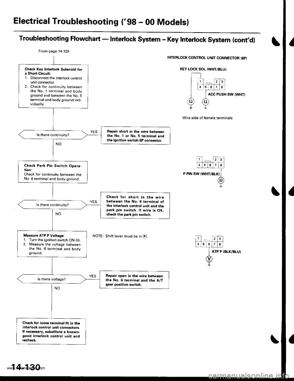
Troubleshooting Flowchart - Interlock System - Key Interlock System (cont,dl
INTERLOCK CONTROL UNIT CONNECTOR {8PI
KEY LOCK SOL (WHT/BI-U}
ACC PUSH SW {WHT)
Wire side of female terminals
ATP P IBLK/BLUI
From page 14'129
Shift lever must be in E.
Check Key Intorlock Solonoid tola Short Circuit:1. Disconnect the interlock controlunit connector,2. Check for continuity betweenthe No. l terminal and bodyground and between the No.5terminal and body ground individually.
Repair shon in thc wire betweonthe No. 1 or No. 5 terminal andth€ ignhion switch 6P connector.
ls there continuity?
Check Park Pin Switch Opera-tion:Check for continuity between theNo. I terminal and body ground.
Check for short in the wir6between the No. 8 terminal ofthe int€rlock control unit and thopark pin switch. ll wire is OK,ch6ck the park pin switch.
ls there continujty?
Moasure ATP P Voftegel1. Turn the ignition switch ON (lli.2. Measure the voltage betweenthe No. 6 terminal and bodyground.
Repair open in the wiro betweenthe No. 6 termin.l and the A/Tgear position 3witch.
Check for looseterminal fit in th€interlock control unit connoctors.lf necosssry, substitute t known-good interlock control unit andrecheck.
14-130
www.emanualpro.com
Page 658 of 1395

A/T Gear Position Indicator
1.
f nput Test -'97 - 98 Models
Remove the gauge assembly from the dashboard (see section 20). and disconnect the 14P connector from the gauge
assemblv (see section 23),
Inspect the connector and socket terminals to be sure they are all making good contact.
. lf the terminals are bent, loose, or corroded, repairthem as necessary, and recheck the system.. lf the terminals look OK, make the following input tests at the 14P connector.- lf I test indicates a problem, find and correct the cause, then recheck the system.- lf all the input tests prove OK, but the indicator is faulty. replace the printed circuit board,
GAUGE ASSEMBLY 14P CONNECTOR
Wire side of female terminals
CavityWirs
ColorTest ConditionTest: Desir€d ResultPossible Cause
{lf rosult is not obtainod)
YEL
lgnition switch ON (ll)Check for voltage to ground:
There should be battery voltage,
. Blown No. 25 (7.5 A) fuse in the
under-dash fuse/relay box. An open in the wire
RE D/BLKCombination light
switch ON and dash
lights brightness con-
trol dial on full bright
Check for voltage between No. 2
and No. 3 terminals;
There should be battery voltage.
Blown No. 47 (7.5 A) fuse in the
under-dash fuse/relay box
Faulty combination Iight switch
Faulty dash iight brightness
controller
An open in the wire
RED
4BLUShift lever in ECheck for continuity to ground:
There should be continuity.
NOTE: There should be no continu-
ity in any other shift lever position.
' Faulty Ay'T gear position switch. An open in the wireBRNShift lever in E
7YELShift lever in @
8BLKUnder all conditionsCheck for continuity to ground:
There should be continuity
. Poor ground {G401). An open in the wire
9GRN/BLK
lgnition switch ON {ll)
and shift lever in any
position except E
Check for voltage to ground:
There should be battery voltage
for two seconds after the ignition
switch is turned ON {ll), and less
than 1 V two seconds later,
' Faulty PCM. An open in the wire
10GRNShift lever in ECheck for continuity to ground:
There should be continuity.
NOTE: There should be no conti-
nuity in any other shift lever posi-
UOn.
. Faulty A,ff gear position switch. An open in the wire1'lREDShift lever in @
12WHTShift lever in E
BLVBLU
Shift lever in ENOTE: Do not push
the brake pedal.
14LT GRN
lgnition switch ON { ll)
and shift lever in any
position except E and
E
Check for voltage to ground:
There should be about 5 V.
. Faulty PCM. An open in the wire
14-142
www.emanualpro.com
Page 659 of 1395

L
Input Test -'99 - 00 Models
Remove the gauge assembly from the dashboard {see section 20), and disconnect the 14P connector from the gauge
assembly (see section 23).
Inspect the connector and socket terminals to be sure they are all making good contact.
a lf the terminals are bent. loose, or corroded. repair them as necessary. and recheck the system.
. lf the terminals look OK, make the following input tests at the 14P connector.- lf a test indicates a problem, find and correct the cause, then recheck the system.- lf all the input tests prove OK, but the indicator is faulty, replace the printed circuit board.
GAUGE ASSEMBLY 14P CONNECTOR
Wire side of female terminals
CavityWire
ColorTest ConditionTest: Desired ResuhPossible Caus6
{lf resutt is not obtainod)
1YEL
lgnition switch ON (ll)Check for voltage to ground:
There should be battery voltage.
. Blown No.25 (7.5 A) fuse in the
under-dash fuse/relay box. An open in the wire
2RE D/BLK
Combination light
switch ON and dash
lights brightness con-
trol dial on full bright
Check for voltage between No. 2
and No.3 terminals:
There should be battery voltage.
Blown No. 47 {7.5 A) fuse in the
under-dash fuse/relay box
Faulty combination light switch
Faulty dash light brightness
controller
An open in the wire
5RED
BRNShift lever in ECheck for continuity to ground:
There should be continuity.
NOTE: There should be no continu-
ity in any other shift lever position.
. Faulty A/T gear position switch. An open in the wire7YELShift lever in E
'10BLUShift lever in E
LT BLU
lgnition switch ON (ll),
shift lever in E. and
Over-Drive is OFF bypressing O/D switch.
Check for continuity to ground:
There should be continuity.
Faulty O/D switch
Faulty A/T gear position switch
Faulty PCM
An open in the wire
8BLKUnder all conditionsCheck for continuity to ground:
There should be continuity
. Poor ground (G401)
. An open in the wire
9a:FI\|/Et| ta
lgnition switch ON (ll)
and shift lever in any
position except E
Check for voltage to groundl
There should be battery voltage
for two seconds after the ignition
switch is turned ON (ll). and less
than 1 V two seconds later.
. Faulty PCM. An open in the wire
11REDShift lever in SCheck for continuity to ground:
There should be continuity.
NOTE: There should be no conti-
nuity in any other shift lever posi-
Iton.
. Faulty A/T gear position switch. An open in the wire12WHTShift lever in E
BLI(BLU
Shift lever in ENOTE: Do not push
the brake pedal.
14LT GRN
lgnition switch ON (ll)
and shift lever in any
position except E and
E
Check for voltage to groundl
There should be about 5 V,
. Faulty PCM. An open in the wire
14-143
www.emanualpro.com
Page 660 of 1395
Interlock System
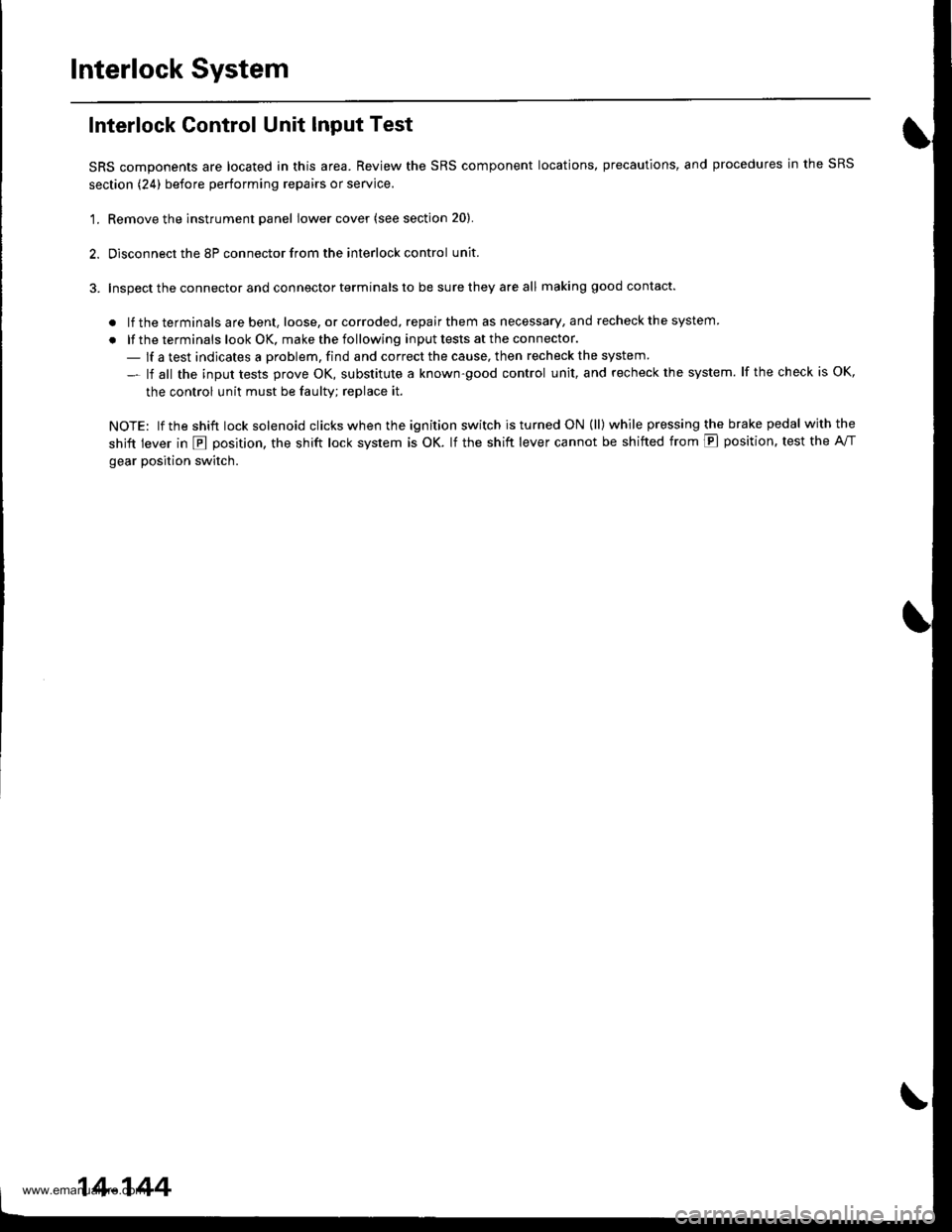
Interlock Control Unit Input Test
SRS components are located in this area. Review the SRS component locations, precautions, and procedures in the SRS
section (24) before performing repairs or service.
'1. Remove the instrument panel lower cover (see section 20).
2. Disconnect the 8P connector from the interlock control unit.
3. Inspect the connector and connector terminals to be sure they are all making good contact.
. lf the terminals are bent, loose, or corroded, repair them as necessary, and recheck the system
. lf the terminals look OK, make the following input tests at the connector.
- lf a test indicates a problem, find and correct the cause, then recheck the system
- lf all the input tests prove OK, substitute a known-good control unit, and recheck the system. lf the check is OK,
the control unit must be faulty; replace it.
NOTE: lf the shift lock solenoid clicks when the ign ition switch is tu rned ON (ll) while pressing the brake pedal withthe
shift lever in E position, the shift lock system is OK. lf the shift lever cannot be shifted from E position. test the A/T
gear position switch.
14-144
www.emanualpro.com
Page 662 of 1395
lnterlock System
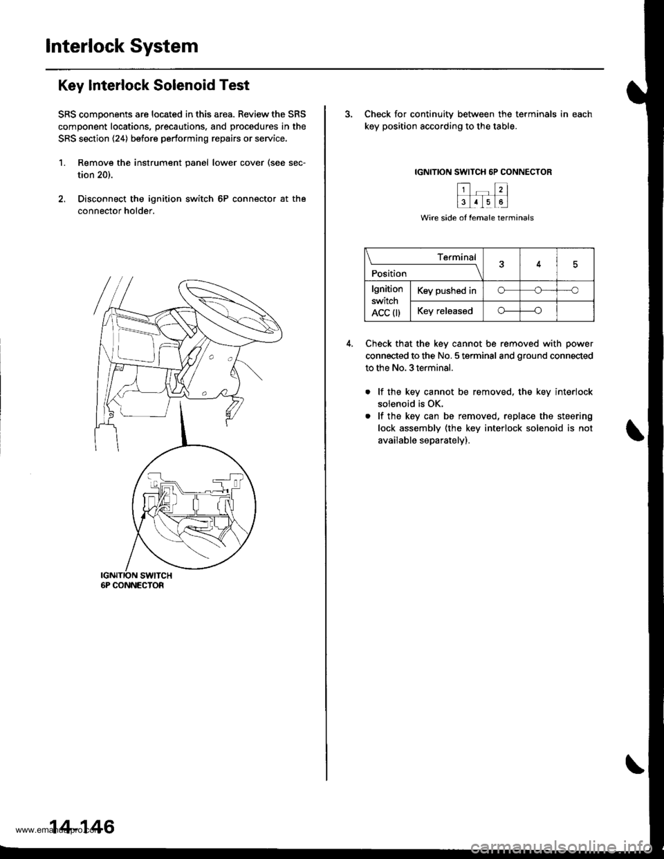
Key Interlock Solenoid Test
SRS comoonents are located in this area. Review the SRS
component locations, precautions. and procedures in the
SRS section (24) before pertorming repairs or service.
1. Remove the instrument panel lower cover (see sec-
tion 20).
2. Disconnect the ignition switch 6P connector at the
connector holder.
6P CONNECTOR
14-146
3. Check for continuitv between the terminals in each
key position according to the table.
IGNITION SWITCH 6P CONNECTOR
Check that the key cannot be removed with power
connected to the No. 5 terminal and ground connected
to the No. 3 terminal.
lf the key cannot be removed. the key interiock
solenoid is OK.
lf the key can be removed, replace the steering
lock assembly (the key interlock solenoid is not
available separately).
\____________r{r4
Position
lgnition
switch
ACC 0)
Key pushed ino---'o
Key releasedo----o
www.emanualpro.com
Page 664 of 1395
Interlock System
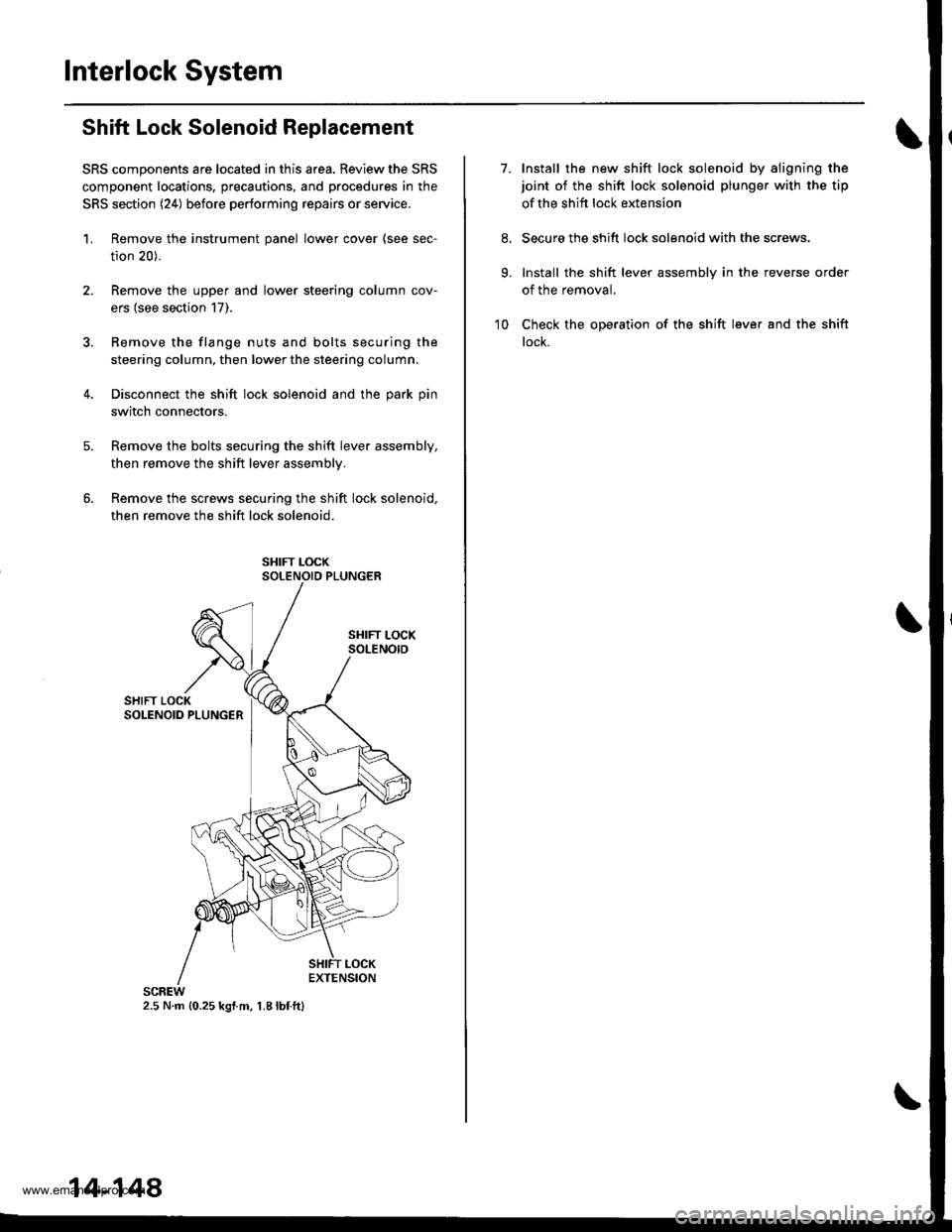
Shift Lock Solenoid Replacement
SRS components are located in this area. Review the SRS
component locations, precautions, and procedures in the
SRS section (24) before performing repairs or service.
'L Remove the instrument panel lower cover (see sec-
tion 20).
2. Remove the upper and lower steering column cov-
ers (see section 17).
3. Bemove the flange nuts and bolts securing the
steering column, then lower the steering column.
4. Disconnect the shift lock solenoid and the park pin
switch connectors.
Remove the bolts securing the shift lever assembly,
then remove the shift lever assemblv.
Remove the screws securing the shift lock solenoid,
then remove the shift lock solenoid.
2.5 N.m {0.25 kgl.m, 1.8lbf.ft}
14-148
7.Install the new shift lock solenoid by aligning the
joint of the shift lock solenoid plunger with the tip
of the shift lock extension
Secure the shift lock solenoid with the screws,
Install the shift lever assembly in the reverse order
of the removal.
Check the operation of the shift lever and the shift
lock.
9.
10
www.emanualpro.com
Page 666 of 1395
Interlock System
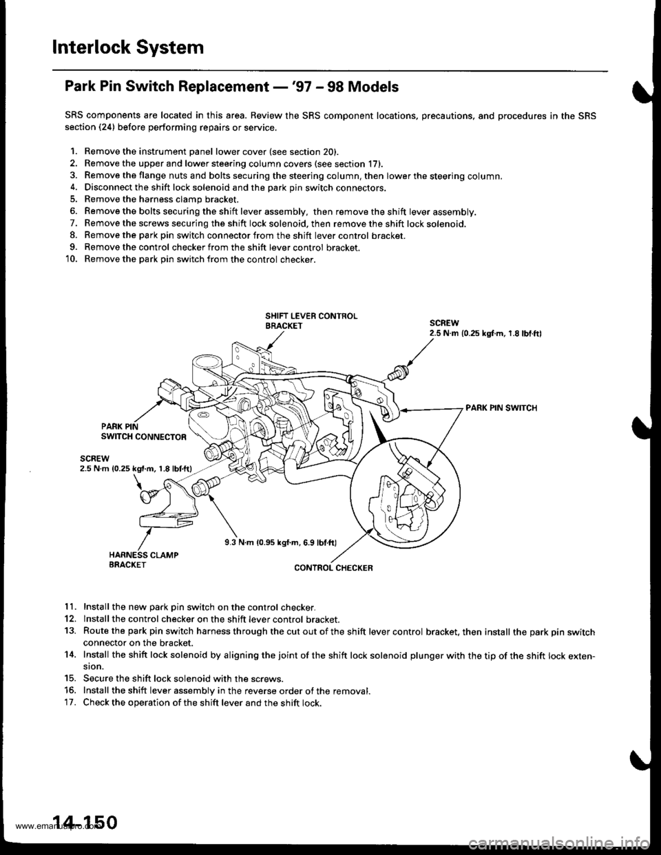
Park Pin Switch Replacement -'97 - 98 Models
SRS components are located in this area. Review the SRS component locations, precautions, and procedures in the SRS
section (24) before performing repairs or service.
1. Remove the instrument Danel lower cover (see section 20).
2. Remove the upper and lower steering column covers (see section li,.
3. Remove the flange nuts and bolts securing the steering column. then lower the steering column.4. Disconnect the shift lock solenoid and the park pin switch connectors.
5. Remove the harness clamp bracket.
6. Remove the bolts secu ring the shift lever assembly, then removetheshift lever assembly.
7. Remove the screws securing the shift lock solenoid. then remove the shift lock solenoid,
8. Remove the parkpin switch connector from the shift lever control bracket.
9. Remove the control checker from the shift lever control bracket.
10. Remove the park Din switch from the control checker.
PARK PIN SWITCH
PARK PINSWITCH CONNECTOR
scnEw2.5 N m 10.25 kgt.m, 1.8 lbtftl
9.3 N.m 10.95 kgf.m, 6.9 lbl.ft)
BRACKETCONTROL CHECKER
11. Install the new Dark Din switch on the control checker.
12. lnstall the control checker on the shift lever control bracket.
13. Routethe park pin switch harness through thecutoutofthe shift lever control bracket, then install the park pin switchconnector on the bracket.
14. Install the sh ift lock solenoid by a ligning the joint of the sh ift lock solenoid plu nger with the tip of the shift lock exten-sion.
15. Secure the shift lock solenoid with the screws.
15. Install the shift lever assembly in the reverse order of the removal.'17. Check the operation of the shift lever and the shift lock.
14-150
www.emanualpro.com
Page 669 of 1395
Symptom-to-Component Chart
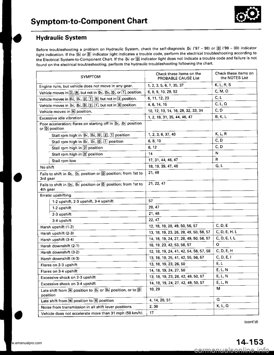
Hydraulic System
Before troubleshooting a problem on Hydraulic system, check the self-diagnosis Dl ('97 - 98) or Lq ('99 - 00) indicator
light indication. lf the El or E indicator light indicates a trouble code, perform the electrical troubleshooting according to
the Electrical System-to-Component Chart. lf the Ol or E indicator light does not indicate a trouble code and failure is not
found on the electrical troubleshooting, perform the hydraulic troubleshooting following the chart.
SYMPTOMCheck these items on the
PROBABLE CAUSE List
Check these items on
the NOTES List
Engine runs, but vehicle does not move in any gear.1r2FAt?82?K,L.R,S
Vehicle moves in El. @, but not in lE. E, E, or E, position6, 8, 9, 10, 29, 52c,M,o
Vehicle moves in [D!. E, E. E, E, but not in E] position.al
Vehicle moves in .&1, E. E, E, E, but not in E position4,6, 14, 15c,L.o
Vehicle moves in E position.10 , 12, 13, '�l4, '16, 2A, 32, 33, 34
Excessive idle vibration1,2, 18,3'1,35, 44, 46, 41B,K,L
Poor acceleration; flares on starting off in E, Di position
or E position
Stall rpm hish in El, El, E, E, E Position
Stall rpm hiqh in E, E, E, E position
1,2,3,6,37, 40K,L,R
6, 8, 10C,D
Stall rpm high in E positionc,D
Stall rpm high in hl position14N
Stall rpm low17,31, 44, 46, 47R
No shift18, 19, 39, 47, 48G,L
Fails to shift in Pr, E position or E position; from 1st to
3rd gear
21, 48
Fails to shift in EJ, E position or E position; from 1st to
4th gear
21,22, 47
Erratic upshifting
fz upshlft. ,3 ripshlft, 3r. up+ilft57
ffi20, 47
il21, 4A
3-4 upshift22, 47
Harsh upshift ('l-2)12, 18, 19,2A,49, 50, 56, 57
Harsh upshift (2-3)13, 1A, 19,23,26,28, 49, 50, 56, 57C,D.E,H,L
Harsh upshift {3-4)14,1A, 19,24,27,28, 49, 50, 56. 57C, D, E, I,L
Harsh downshitt (2-1)18, 19,23, 42,53,56,51o
Harsh downshift (3-2)12, 18,19,24,41,42, 54. 56, 57, 58
Harsh downshift (4-3)13,'1A, 19, 25, 41, 42, 55, 56, 57C, D, E, I
Flares on 2-3 upshift13,1A,19,23,26,50FI
Flares on 3-4 upshift14, 1A, 19,24,27,50E,L,N
Excessive shock on 2-3 upshift13. '18, 19 , 23, 26, 42, 49 , 50, 51E.L.N
Excessive shock on 3-4 upshift14, 1A, 19,24,27 , 42, 49,50,51E,L,N
Late shift from N position to ld or Erl position. or to E
position
10, 29M
Late shift from E position to E position4, 14,20,51o
Noise from transmission in all shift lever positions2,36K,L.O
Vehicle does not accelerate more than 3l mph (50 km/h).11
(cont'd)
14-153
www.emanualpro.com
Page 670 of 1395
Symptom-to-Component Chart
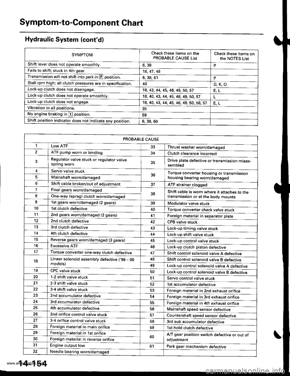
Hydraulic System (cont'd)
SYMPTOMCheck these items on thePROBABLE CAUSE ListCheck these items onthe NOTES Lisr
Shift lever does not operate smoothly.o, JdPFails to shift; stuck in 4th gear.14, 41 , 48
Transmission will not shift into park in E position.6, 38, 61PStall rpm high; all clutch pressures are in specification.40D,K,OLock-up clutch does not disengage.18, 43, 44, 45, 46, 49,50,57
Lock-up clutch does not operate smoothly.14, 40, 43, 44, 45, 46, 49, 50. 57Lock-up clutch does not engage.'t8, 40, 43, 44, 45, 46, 49, 50, 56, 57Vibration in all positions.
No engine braking in I position.59
Shift position indicator does not indicate anv position,6. 38, 60
PROBABLE CAUSE
I 33 Thrust washer worn/damaged
ATF pump worn or binding34Clutch clearance incorrect
Regulator valve stuck or regulator valvespflng wornDrive plate delective or transmission mtsas-sembled
Servo valve stuck5ttTorque converter housing or transmissionhousing bearing worn/damagedMainshaft worn/damaged
Shift cable broken/out of adjustmentATF strainer clogged
7Final gears worn/damaged38Shift cable is worn where it attaches to thetransmission or at the body mountsIOne-way (sprag) clutch worn/damaged
1st gears worn/damaged {2 gears)39Modulator valve stuck10lst clutch defective40Torque converter check valve stuck112nd gears worn/damaged (2 gears)41Foreign material in separator plate't22nd clutch defectiveCPB valve stuck
t53rd clutch defective43Lock-up timing valve stuck144th clutch defective44Lock-up shift valve stucktcReverse gears worn/damaged (3 gears)Lock-up control valve stuck16Excessive ATF46Lock-up clutch Diston defective17Torque converter one-way clutch defective47Shift control solenoid valve A defecttve
18Linear solenoid assemblv defective (,98 - OOmodels)48Shift control solenoid valve B dsfectrve
49Lock-up control solenoid valve A defective'19CPC valve stuckLock-up control solenoid valve B deleqtve20l-2 shift valve stuck51Servo control valve stuck212-3 shift valve stuck52lst accumulator defective3-4 shift valve stuck53Foreign material in 2nd exhaust orifice2nd accumulator defective54Foreign material in 3rd exhaust orifice3rd accumulator defectiveForeign material in 4th exhaust orifice4th accumulator defective56Mainshaft speed sensor defective262nd orifice control valve stuckCountershaft speed sensor defective273-4 orifice control valve stuck583rd sub accumulator defective2aForeign material in main orifice59lst-hold clutch defective29Foreign material in lst orifice60A/T gear position switch defective or out ofadjustment30Foreign material in reverse orifice
31Engine output low61Park gear mechanism defective32Needle bearing worn/damaged
14-154
www.emanualpro.com