Gear HONDA CR-V 1998 RD1-RD3 / 1.G Workshop Manual
[x] Cancel search | Manufacturer: HONDA, Model Year: 1998, Model line: CR-V, Model: HONDA CR-V 1998 RD1-RD3 / 1.GPages: 1395, PDF Size: 35.62 MB
Page 1206 of 1395

Ground Distribution
Ground-to-Component(sl Index
GroundWire Color
G2
G3
G 10'l
G201
G202
G351
BLIVRED
BRN
BLK
BLK
BRN/BLK
BLK
BLK
BLK
23-46
Component or Circuits Grounded
Battery
Valve Cover
Transmission housing
A,/T gear position switch
ECM (PG1, PG2) ('98 - 00 models: M/T)
PCM (PG1, PG2l (Avrr)
PGM-FI main relay
Power steering pressure (PSP) switch
Radiator fan switch
VSS
Data link connector
ECM (1G1, LG2) ('98 - 00 models: M/T)
PCM (LGI, LG2) (IVT)
Shielding:
between ECM ('98 - 00 models: M/T) or PCM (Ay'T) and CKF sensorbetween ECM {'98 - 00 modets: M/T} or pCM (Ay'T) and CKp sensorbetween ECM ('98 - 00 models: M/T) or PCM (rVT) and CYP sensorbetween ECM ('98 - 00 models: M/T) or PCM (Ay'T) and TDC sensorbetween ECM {'98 - 00 models: M/T) or PCM (ly'T) and countershaft speed sensor (Ay'T)
between ECM ('98 - 00 models: M/T) or PCM {A,,/T) and mainshaft sp€ed sensor {!VT)between ECM ('98 - 00 models: M/T) or PCM (A,/T) and primary HO2Sbetween ECM ('98 - 00 models: M/T) or PCM (Ay'T) and secondary HO2SHorn (High)
Horn {Low}
Radiator fan motor
Right headlight
Right front parking light
Right front side marker light
Right front turn signal light
Condenser fan motor
Cruise actuator
Left front parking light
Left front side marker light
Left front turn signal light
Left headlight
Rear window washer motor
Windshield washer motor
ABS pump motor
www.emanualpro.com
Page 1207 of 1395

BLKG401
GroundWir€ ColorComponent or Circuits Grounded
ABS indicator circuit
ABS control unit
Ashtray light
A/T gear position indicator dimming circuit
Brake fluid level switch
Clock ('98 - 00 models)
Clutch inrerlock switch (M/T)
Clutch switch (Mff)
Cruise main switch
Cruise indicator circuit
Cruise control unit
Dash lights brightness controller
Data iink connector
Daytime running rights control unit (Canada)
Front accessary socket
Gauge and indicators
Heater control panel
lgnition key light control unit ('97 model)
lgnition key switch
Integrated control unit
Interlock control unit (Ay'T)
Parking pin switch {A,/T)
Power window relay
Rear accessary socket relay
Bear window defogger relay
Rear window wiper control unit ('97 model)
Service check connector
Spotlights
SRS indicator circuit
Turn signal/hazard relay
Windshield wiper motor
Windshield wiper/washer switch- plus everything grounded through G402
ABS control unit
Blower motor relay
Blower motor high relay
ELD unit (USA)
Power transistor- plus everything grounded through G401
BLKG402
{cont'd)
23-47
www.emanualpro.com
Page 1217 of 1395
l-
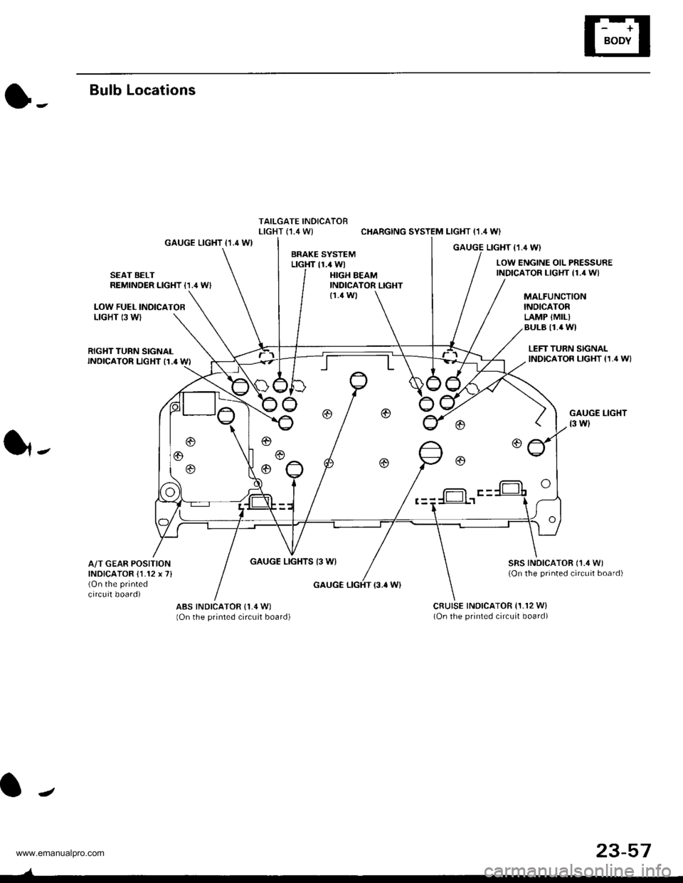
Bulb Locations
TAILGATE INDICATORLIGHT (,I.4 W) CHARGING SYSTEM LIGHT (1.4 WI
GAUGE LIGHT {1.4 WIGAUGE LIGHT I1,4 WIBRAKE SYSTEMLTGHT 11.4 WlLOW ENGINE OIL PRESSUREINDICATOR LIGHT {1./r W}SEAT BELTREMINDER LIGHT {1.' W'HIGH BEAMINDICATOR LIGHT
LOW FUEL INOICATOBLIGHT 13 WI
MALFUNCTIONINOICATORLAMP {MIL)BULB I1.4 WI
{1.4 Wl
RIGHT TURN SIGNALINDICATOR LIGHT I1.' WI
GAUGE LIGHTS 13 WI
LEFT TURN SIGNALINDICATOR LIGHT {1,4 W}
GAUGE LIGHT
t3 wl
SRS INDICATOR ('1./t W)(On the printed circuit board)
1,.
A/T GEAR POSITIONINDICATOR {1.12 x 7}(On the printed
circuit board)GAUGE LIGHT {3.' W}
ABS INDICATOR (1,4 W)
lOn the printed circuit board)cRutsE tNDtcAToR 11.r2 w)(On the printed circuit board)
f-= F -
J
23-57
www.emanualpro.com
Page 1225 of 1395
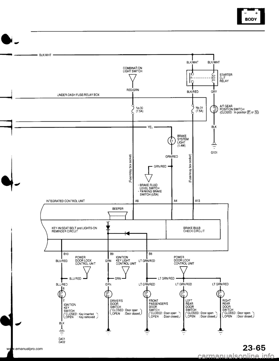
< - ELK/WHT
S'TARTEBCUTRELAY
A,/rGEARPOSrr 0N SWTTCH(CLOSED :ln postion Eor N)
COMBINATONLIGHT SWITCH
\-/
IRED/GRN
I
.l-
NTEGRATED CONTROL UNIT
POWERDOOR LOCKCONTROL UNIT
I B1o PowERBLU/RED DOOR LOCK
I CONTFOL UN T
IY
F r,r'tro J
BLUi RED
"l\
u/
llon. no*
155,1'*IaCLOSED Keylnseded
| \oPEN Key rcmoved
8LK
4
G40r
LTGRN/RED LTGRN/RED LTtl
/rh d[)v !s-l
I FFONT I LEFTI PASSENGEBS I REABI DOOR | 00ORoDen ) lSwlTcH I SWITCHdosedJ J f C-OSED : ooot ooer ) | f CLOSED : Door opel
| ( ooE Doot dosed,r | \oPEN Doo' closed
tl_L -._:-
1,,,,,"
Yilei'rGRN/RED
. BNAKE FLUIOLEVEL SWITCH.PARKING ERAKEswrTcH (usA)
A8
BRAKE BULBCHECKCIFCUTKEY.IN]SEAT BELT and LIGHTS'ONREMINDER C RCU T
23-65
www.emanualpro.com
Page 1230 of 1395
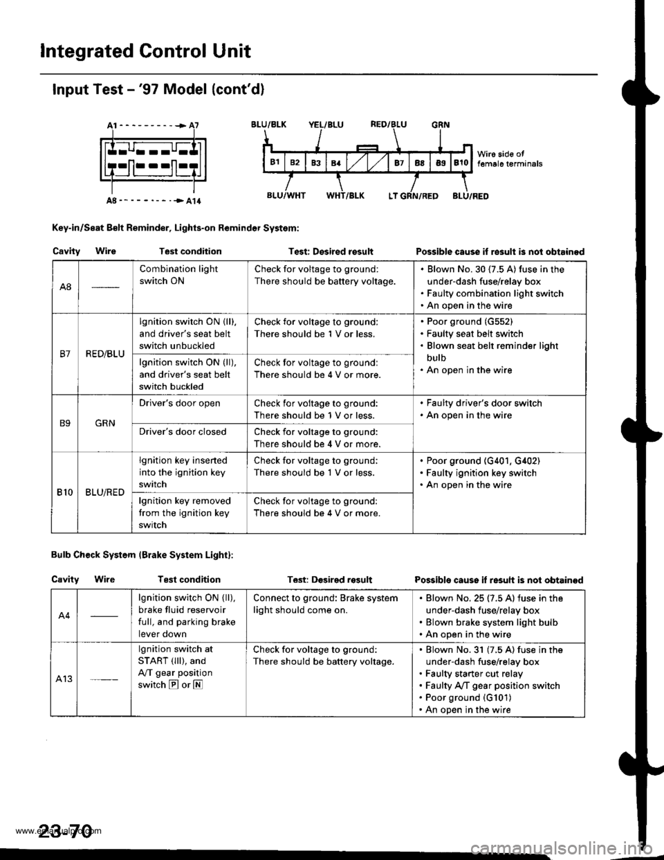
lntegrated Control Unit
Input Test -'97 Model (cont'd)
At----------+A7
Key-in/Seat Belt Reminder, Lights-on Remindor System:
Cavity WireTest conditionTest: Desired rosultPossible cause if re3ult is nol obtainod
Bulb Check System (Brake System Light):
Cavity WireTest conditionT6st: DGsirgd rosultPossible cause if resuh is not obtainod
23-70
A8
Combination light
switch ON
Check for voltage to ground:
There should be battery voltage.
Blown No.30 (7.5 A) fuse in the
under-dash fuse/relay box
Faulty combination light switch
An open in the wire
B7R ED/BLU
lgnition switch ON {lll.
and driver's seat belt
switch unbuckled
Check for voltage to ground:
There should be 1 V or less.
Poor ground (G552)
Faulty seat belt switch
Blown seat belt reminder light
bulb
An open in the wirelgnition switch ON (ll),
and driver's seat belt
switch buckled
Check for voltage to groundl
There should be 4 V or more.
B9GRN
Driver's door openCheck ior voltage to ground:
There should be 1 V or less.
. Faulty driver's door switch. An open in the wire
Driver's door closedCheck for voltage to ground:
There should be 4 V or more.
810BLU/RED
lgnition key insened
into the ignition key
switch
Check for voltage to ground;
There should be 1 V or less.
Poor ground (G401, G,[02)
Faulty ignition key switch
An open in the wire
lgnition key removed
trom the ignition key
swrtch
Check for voltage to ground:
There should be 4 V or more.
A4
lgnition switch ON { ll),
brake fluid reservoir
full, and parking brake
tever oown
Connect to ground: Brake system
light should come on.
Blown No. 25 (7.5 A) iuse in the
under-dash fuse/relay box
Blown brake system light bulb
An open in the wire
A13
lgnition switch at
START (lll), and
A/T gear position
switch E or E
Check for voltage to ground:
There should be battery voltage.
Blown No.31 (7.5 A) fuse in the
under-dash fuse/relay box
Faulty starter cut relay
Faulty A/f gear position switch
Poor ground (G101)
An open in the wire
www.emanualpro.com
Page 1234 of 1395
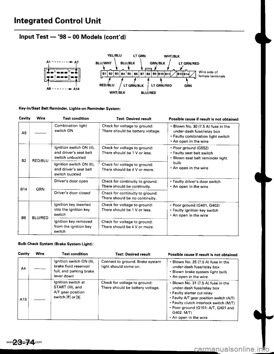
Integrated Control Unit
A1 --------> A7
Input Test -'98 - 00 Models (cont'dl
YEL/BLULT GRNWHT/BLK
GRN/BLKLT GRN/REO
Wire side offemale terminals
A8------->A14WHT/BLK
Key-in/Se8t Beft Reminder, Lights-on Remindol System:
BLU/RED
Cavity WireTest conditionTest: Desired resultPossible caus€ it result is not obtained
Bulb Check System lBrake System Lightl:
Cavity WireTest conditionTest: Desired resultPossible caus€ if result is not obtained
A4
lgnition switch ON (ll),
brake fluid reservoir
full, and parking brake
lever down
Connect to ground: Brake system
light should come on.
Blown No. 25 (7.5 A) fuse in the
under-dash fuse/relay box
Blown brake system light bulb
An open in the wire
A13
lgnition switch at
START ( lll), and
A,/T gear position
switch E or E
Check for voltage to ground:
There should be battery voltage.
Blown No. 31 {7.5 A) fuse in the
under-dash fuse/relay box
Faulty sta rter cut relay
Faulty A,/T gear position switch (A,/T)
Faulty clutch interlock switch (M/T)
Poor ground {G101: AfI. G401 and
G402: M/T)
An open in the wire
23-74
A8
Combination light
switch ON
Check for voltage to ground:
There should be battery voltage.
Blown No. 30 (7.5 A) fuse in the
under-dash fuse/relay box
Faulty combination light switch
An open in the wire
RED/BLU
lgnition switch ON ( ll),
and driver's seat belt
switch unbuckled
Check for voltage to ground:
There should be 1 V or less.
Poor ground {G552)
Faulty seat belt switch
Blown seat belt reminder light
bu lb
An open in the wirelgnition switch ON (ll),
and driver's seat belt
switch buckled
Check for voltage to ground:
There should be 4 V or more.
814GRN
Driver's door openCheck for continuity to ground:
There should be continuity,
. Faulty driver's door switch. An open in the wire
Driver's door closedCheck for continuity to ground:
There should be no continuity.
B8BLU/RED
lgnition key inserted
into the ignition key
swrtch
Check for voltage to ground:
There should be 'l V or less.
Poor ground (G401, G402)
Faulty ignition key switch
An open in the wire
lgnition key removed
from the ignition key
switch
Check for voltage to ground:
There should be 4 V or more.
www.emanualpro.com
Page 1241 of 1395
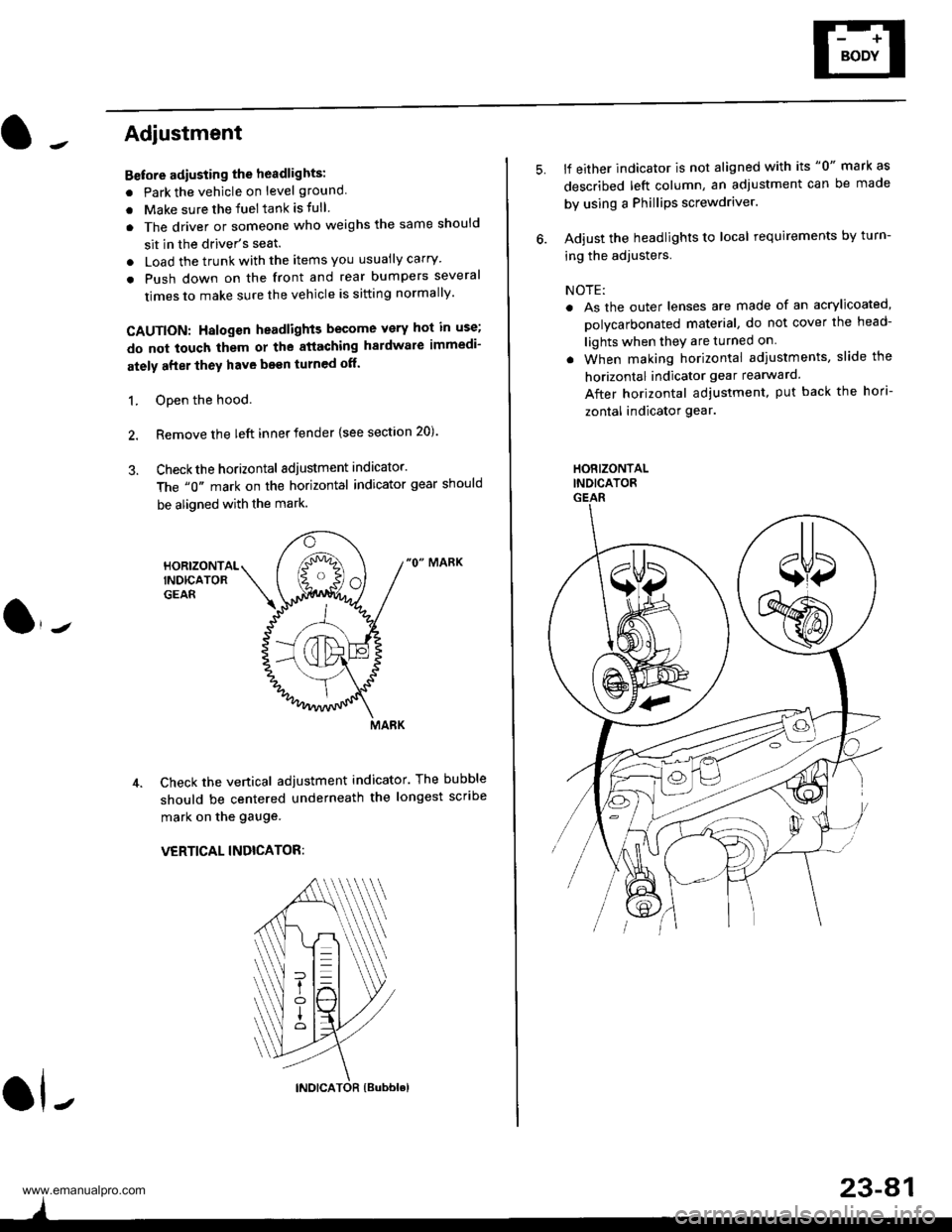
Adjustment
Bstore adiusting the headlights:
. Park the vehicle on level ground
. Make sure the fuel tank is tull
. The driver or someone who weighs the same should
sit in the driver's seat.
. Load the trunk with the items you usually carry'
. Push down on the front and rear bumpers several
times to make sure the vehicle is sitting normally'
CAUTION: Halogen headlights become very hot in use;
do not touch them or the atiaching hardware immedi-
ately after they have been turned off.
1. ODen the hood.
2. Remove the left inner fender {see section 20).
3. Checkthe horizontal adjustment indicator.
The "0" mark on the horizontal indicator gear should
be aligned with the mark.
"0" MARK
Check the vertical adjustment indicator. The bubble
should be centered underneath the longest scribe
mark on the gauge.
VERTICAL INDICATOR:
ol-
)
5.lf either indicator is not aligned with its "0" mark as
described left column, an adjustment can be made
by using a Phillips screwdriver.
Adjust the headlights to local requirements by turn-
ing the adjusters.
NOTE:
. As the outer lenses are made of an acrylicoated,
polycarbonated material, do not cover the head-
lights when they are turned on
. When making horizontal adiustments, slide the
horizontal indicator gear rearward.
After horizontal adjustment, put back the hori-
zontal indicator gear.
HORIZONTALINDICATORGEAR
23-A1
www.emanualpro.com
Page 1243 of 1395
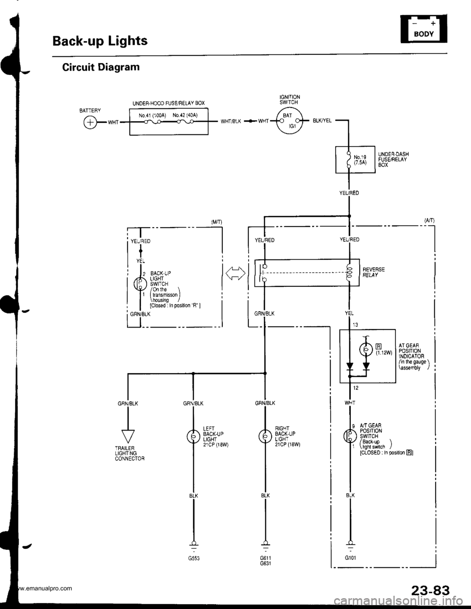
Back-up Lights
Circuit Diagram
(M/r)
I
I
8LK
I
G101
GRN/BLK
I
TBLK
I
UNDEN-HOOD FUSE/RELAY BOX
BACK,UPLIGHTswtTcH/0n1he \I lransmisson J
o!s { /lolosed : In posilion R l
LEFIBACK,UPLIGHT21CP (18W)
*"_,,. _*,,@_ "*"
]__
_..'
iu.Er.w
-r-
RIGHTBACK,UPLGHT21CP 08W)
A,/IGEARPosrl0NswtTcH/Back'up \\l€hl swilch ,/ICLOSED : In posilion [8ll
www.emanualpro.com