Transmission
Reassembly lcont'd)
44.
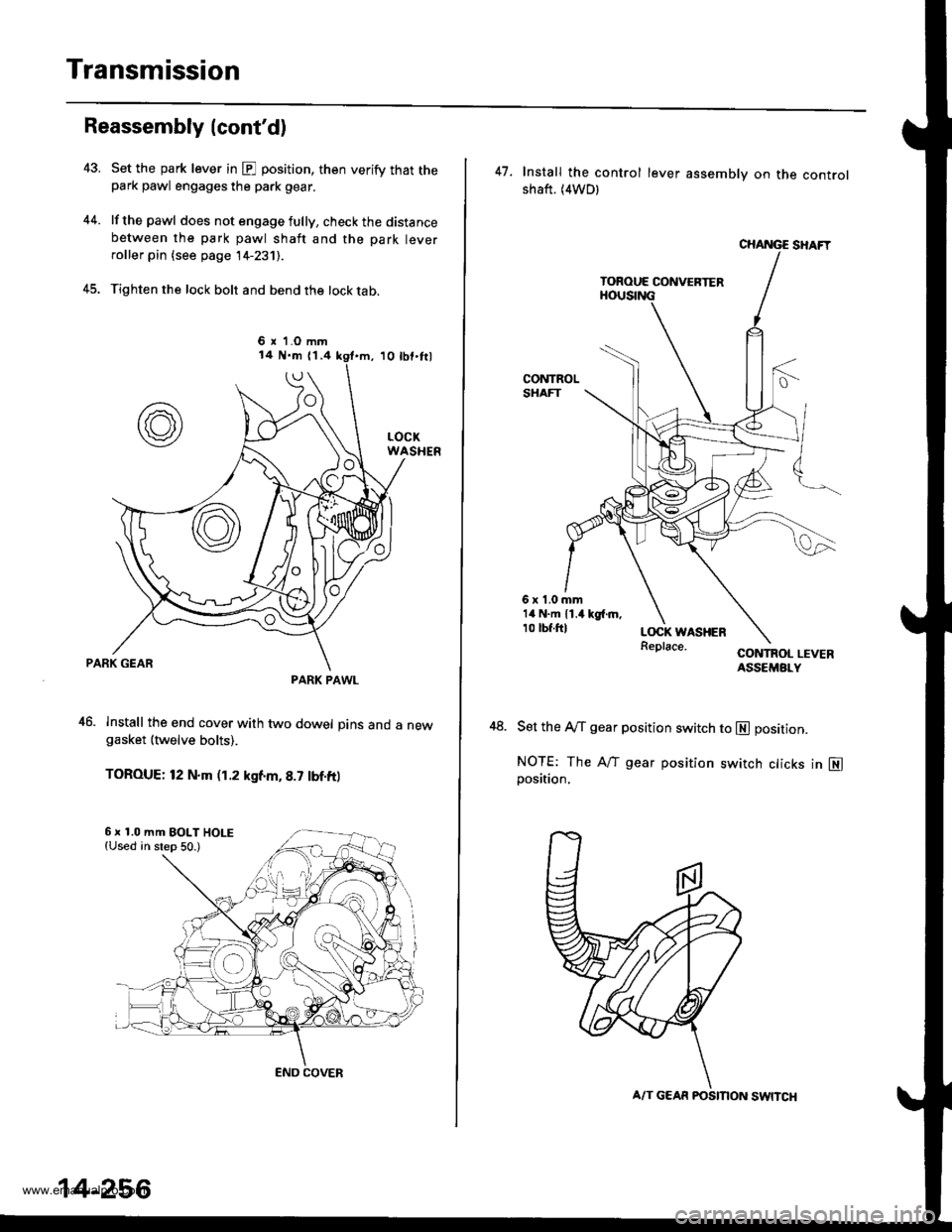
Set the park lever in @ position, then verify that thepark pawl engages the park gear.
lf the pawl does not engage fully, check the distancebetween the park pawl shaft and the park leverroller pin (see page 14-231).
Tighten the lock bolt and bend the lock tab.
1o tbf'frl
PARK GEAR
46. Install the end cover with two dowel pins and a newgasket {twelve bolts).
TOROUE: 12 N.m (1.2 kgf.m, 8.7 tbf.ft)
6 r 1.O mm
PARK PAWL
6 x 1.0 mm EOLT HOLE{Used in step 50.)
END COVER
14-256
A/T GEAR FOSMON SWNCH
47. Install the control lever assemblv on the controlshaft. (4WDl
6x1.0mm14 N.m 11.4 kg{.m,10 tbf.ftl
48.
CONTROL LEVERASSEMBLY
Set the A/f gear position switch to E] position.
NOTE: The Aff gear position switch cticks in N]position,
www.emanualpro.com
Transmission
Installation (cont'dl
2WD:
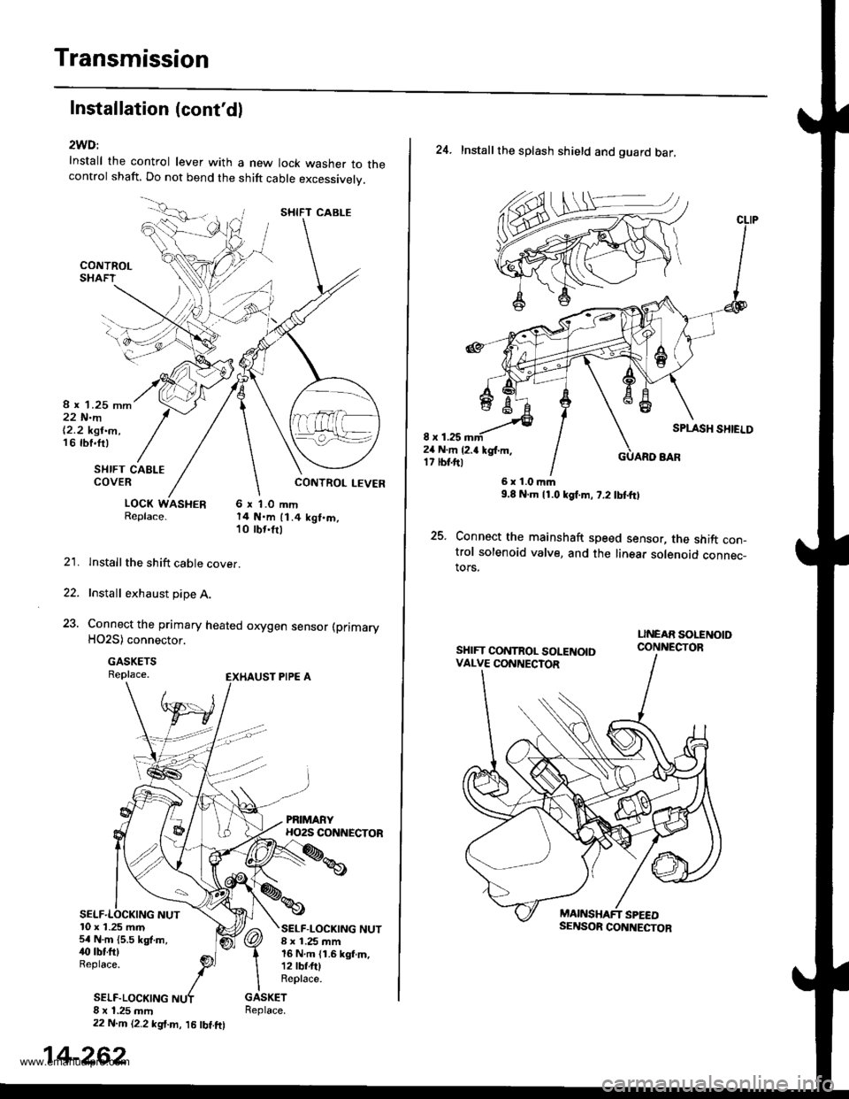
Install the control lever with a new lock washer to thecontrol shaft. Do not bend the shift cable excessivelv.
8 r 1.25 mm22 N.m|'2.2 kgt.m,16 rbf.ft)
SI{IFT CAELECOVER
LOCK WASHER 6 x 1.0 mmReplace. 14 N.m 11.4 kgt.m,10 tbr.frl
lnstallthe shift cable cover.
Install exhaust pipe A.
Connect the primary heated orygen sensor (primary
HO2S) connector.
GASKETSReplace.
22.
23.
10 x 1.25 m.n5r N.m {5.5 kgf.m,40 tbtftlReplace.
SELF.LOCKING
SELF-LOCKING NUT8 ! 1.25 mm16 N.m {1.6 kgf.m,12 lbf.fttReplace.
8 x 1.25 mm22 N.m {2,2 kgt.m, l5 lbt.ftl
SHIFT CABLE
14-262
24. Installthe splash shield and guard bar,
8 x 1.2524 N.m {2.a kgl.m,17 tbt.ftl
SPLASH SHIELD
GUARO BAR
25.
6r1.0|r|m9.8 N.m l1.0lgf.m, 7.2 tbtftl
Connect the mainshaft speed sensor, the shift con-trol solenoid valve, and the linear solenoid connec_tors,
SHIFT CONTROL SOLENOIDVALVE CONNECTOR
www.emanualpro.com

