Cover gasket HONDA CR-V 1998 RD1-RD3 / 1.G User Guide
[x] Cancel search | Manufacturer: HONDA, Model Year: 1998, Model line: CR-V, Model: HONDA CR-V 1998 RD1-RD3 / 1.GPages: 1395, PDF Size: 35.62 MB
Page 378 of 1395
Fuel Supply System
Fuel Tube/Ouick-Connect Fittings {cont'd)
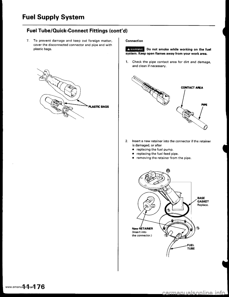
7. To prevent damage and keep out foreign matter.
cover the disconnected connector and oioe end with
plastic bags.
PL TSnC EAGS
11-176
Connection
E!@ Do not smoke white working on the fuel
system. Keep oper flamss away flom your work atea.
1. Check the pipe contact area for din and damage,
and clean if necessary.
Insen a new retainer into the connector if the retainer
is damaged, or after
. replacing the fuel pump.
. replacing the fuel feed pipe.
. removing the retainer from the pipe.
AASEGASKETBeplace.
COiITACT AiEA
www.emanualpro.com
Page 510 of 1395
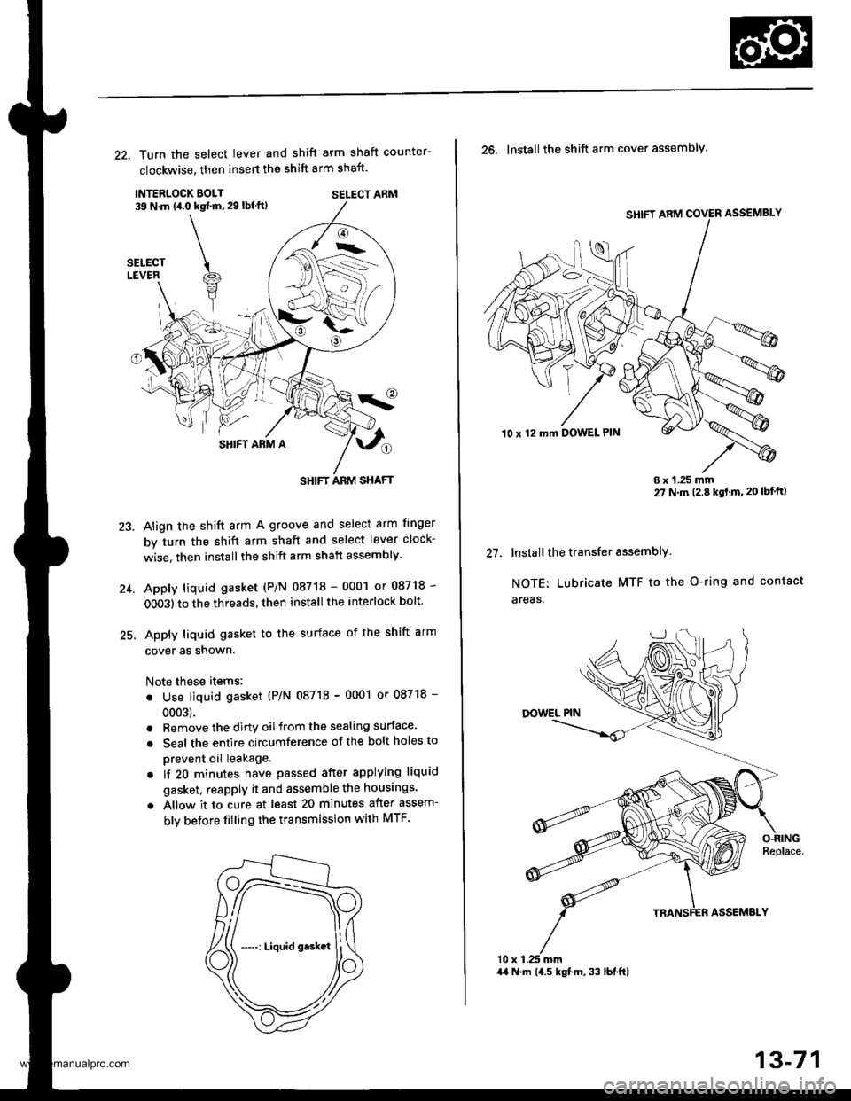
22. Turn the select lever and shift arm shaft counter-
clockwise, then insert the shift arm shaft.
INTERLOCK EOLT39 N.m (4.0 kqt ft, 29 lbf ft)SELECT ARM
SHIFT ARM A
Align the shift arm A groove and select arm finger
by turn the shift arm shaft and select lever clock-
wise. then installthe shift arm shaft assembly.
Apply liquid gasket (P/N 08718 - 0001 or 08718 -
OO03) to the threads, then install the interlock bolt'
Apply liquid gasket to the surface of the shift arm
cover as snown.
Note these items:
. Use liquid gasket (P/N 08718 - 0001 or 08718 -
0003).
. Remove the dirtv oilfrom the sealing surface.
. Seal the entire circumference of the bolt holes to
prevent oil leakage.
. lf 20 minutes have passed after applying liquid
gasket. reapply it and assemble the housings.
a Allow it to cure at least 20 minutes after assem-
bly betore filling the transmission with MTF.
23.
-->.-
(
SHIFT ARM SHAFT
SHIFT ARM COVER ASSEMBLY
10 x 12 mft DOWEL PIN
t1
26. Install the shift arm cover assembly.
I x 1.25 mm27 N m 12.8 kgt m,20 lbf'ft)
Install the transfer assemblY.
NOTE: Lubricate MTF to the O-ring and contact
areas.
10 x 1.25 mm44 N.m 14.5 kgf.m, 33 lbl.ftl
13-71
www.emanualpro.com
Page 652 of 1395
Shift Control Solenoid Valve A/B Assembly
Test
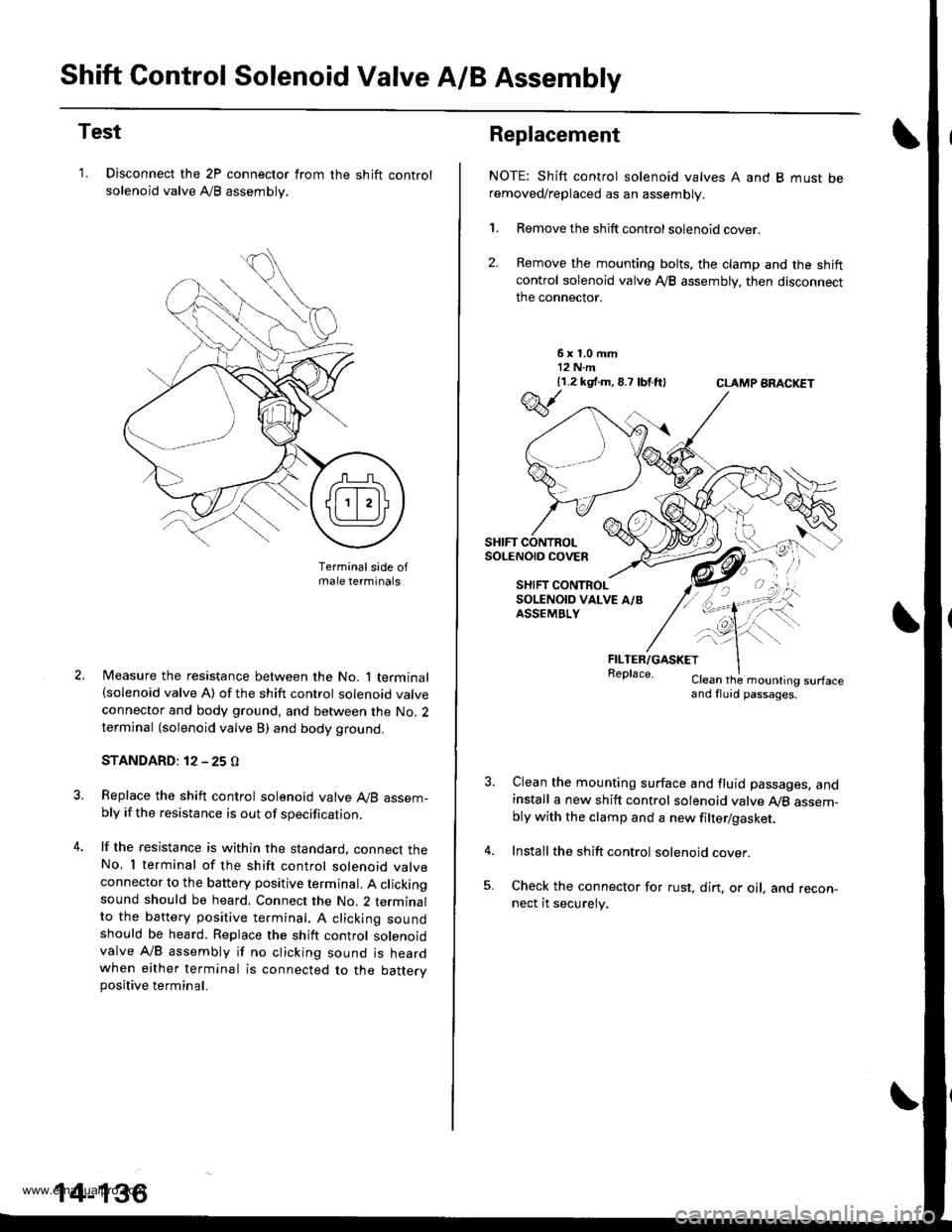
'1. Disconnect the 2P connector from
solenoid valve Ay'B assembly.
the shift control
Terminalsade ofmale terminals
Measure the resistance between the No. 1 terminal(solenoid valve A) of the shift control solenoid valve
connector and body ground, and between the No. 2terminal (solenoid valve B) and body ground.
STANDARD: 12 - 25 O
Replace the shift control solenoid valve A,/B assem-bly if the resistance is out of specification.
lf the resistance is within the standard. connect theNo, I terminal of the shift control solenoid valveconnector to the battery positive terminal. A clickingsound should be heard. Connect the No. 2 terminalto the battery positive te.minal. A clicking soundshould be heard. Replace the shift control solenoidvalve A/B assembly if no clicking sound is heardwhen either terminal is connected to the battervpositive terminal.
14-136
Replacement
NOTE: Shift control solenoid valves A and B must beremoved/replaced as an assembly.
1. Remove the shift control solenoid cover.
2. Remove the mounting bolts, the clamp and the shiftcontrol solenoid valve Ay'B assembly, then disconnect
the connector.
6x1.0mm12 N.m{1.2 k9 .m,8.7 lbtft}CLAMP ARACKET
FILTER/GASKETReplace.Clean the mounling surfaceand fluid passages.
Clean the mounting surface and fluid passages. andinstall a new shift control solenoid valve Ay'B assem-bly with the clamp and a new filter/gasket.
Install the shift control solenoid cover.
Check the connector for rust, dirt. or oil, and recon-nect it securely.
w
SHIFT CONTROLSoLENO|O COVEn
SHIFT CONTROLSOLENOID VALVE A/BASSEMBLY
\--
qK
-!t'">,,
www.emanualpro.com
Page 654 of 1395
Mai nshaft /Cou ntershaft
Linear Solenoid AssemblySpeed Sensors
Replacement
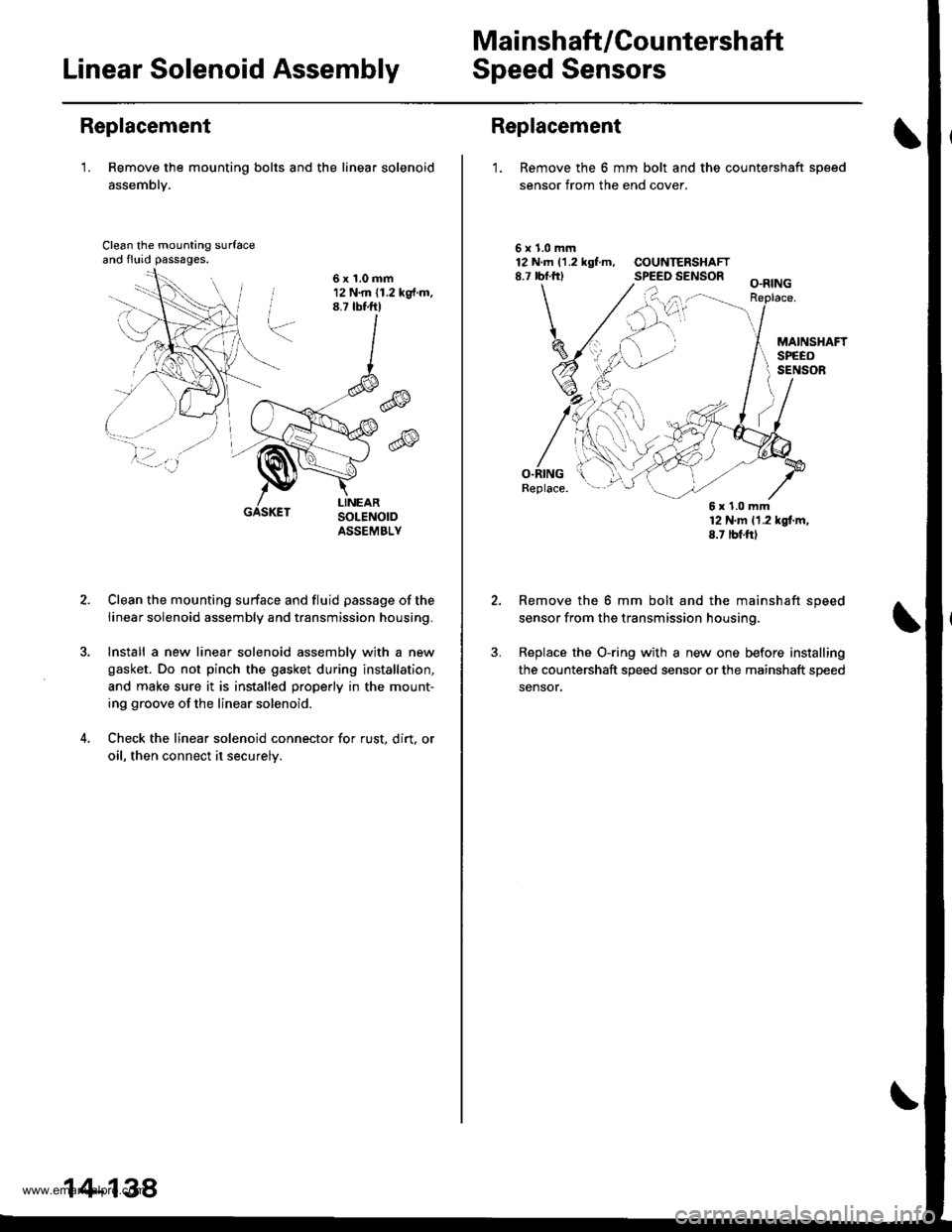
'1. Remove the mounting bolts and the linear solenoid
assemblY.
Clean the mounting surfaceand fluid passages.
6x1.0mm12 N.m (1.2 kg{.m.8.7 tbtftl
@
@
GASKET
Clean the mounting surface and fluid passage of the
linear solenoid assembly and transmission housing.
Install a new linear solenoid assemblv with a new
gasket. Do not pinch the gasket during installation,
and make sure it is installed properly in the mount-
ing groove of the linear solenoid.
Check the linear solenoid connector for rust. dirt, or
oil, then connect it securelv.
14-138
Replacement
1. Remove the 6 mm bolt and the countershaft sDeed
sensor from the end cover.
\
5x1.0mm12 N.m 11.2 kgf.m, COUNTERSHAFT8.7 rbf.frl SPEED SENSOR
O.RINGReplace.
12 N'm 11.2 kgl.m,8.7 tbf.ftl
Remove the 6 mm bolt and the mainshaft speed
sensor from the transmission housing.
Replace the O-ring with a new one before installing
the countershaft speed sensor or the mainshaft speed
sensor,
6x1.0mm
www.emanualpro.com
Page 687 of 1395
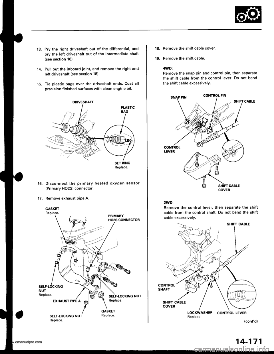
13.Pry the right driveshaft out of the differential. and
orv the left driveshaft out of the intermediate shaft
{see section 16).
Pull out the inboard joint, and remove the right and
left driveshaft (see section 18).
Tie plastic bags over the driveshaft ends. Coat all
Drecision finished surfaces with clean engine oil.
Disconnect the primary heated oxygen sensor
(Primary HO2S) connector.
Remove exhaust pipe A.
GASKETReplace.
14.
16.
't7 .
ORIVESHAFT
Replace.
EXHAUST
14-171
18.
19.
Remove the shift cable cover.
Remove the shift cable.
ilWD:
Remove the snap pin and control pin, then separate
the shift cable from the control lever. Do not bend
the shift cable excessively.
2WD:
Remove the control lever, then separate the shift
cable from the control shaft. Do not bend the shift
cable excessivelv.
Replace.
SHIFT CAELE
www.emanualpro.com
Page 691 of 1395
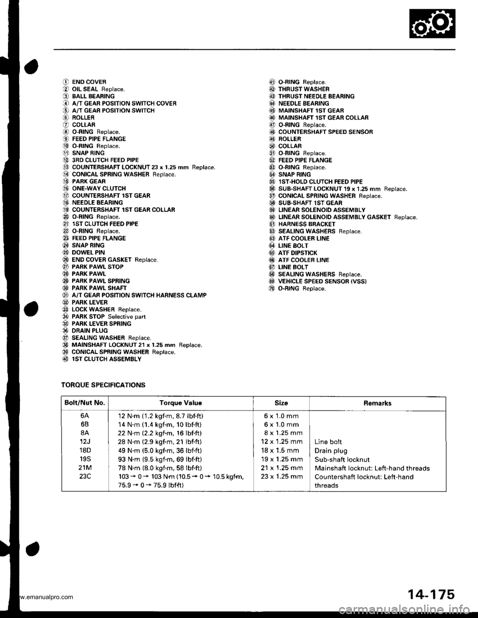
O END COVER
O olL SEAL Replace.
O BALL BEARING
@ A/T GEAR PoSITIoN swITcH coVER
€) A/T GEAn PosrloN swrrcH
@ ROLLER
O coLLARG) o-RING Replace.{9) FEED PIPE FLANGE
@ O-RING Replace.
O SNAP RING
@ 3RD CLUTCH FEED PIPE(D CoUNTERSHAFT LOCKNUT 23 x 1.25 mm Replace.(} coNtcAL SPR|NG WASHER Reptace.
@ PARK GEAR@ ONE.WAY CLUTCH(, COUNTENSHAFT lST GEAR(D NEEOLE BEARING(O COUNTERSHAFT lST GEAR COLLAR
@ o-RING Reptace.
@ lST CLUTCH FEED PIPE
@ O-RING Reptace.
@} FEEO PIPE FLANGE
@ SNAP RING
@ DOWEL PIN
@ END coVER GASKET Feplace.
@ PARK PAWL SToP@ PARK PAWL
@ PARK PAWL SPRING
@ PARK PAWL SHAFT
O} A/T GEAR POSITION SWITCH HARNESS CLAMP
@ PARK LEVER
@ LOCK WASHER Replace.
@ PARK STOP Selective part
@ PARK LEVER SPRING@ DRAIN PLUG
O SEALING WASHER Reptace.
@) MAINSHAFT LOCKNUT2l x 1.25 mm Replace.@ CONICAL SPRING WASHER Replace.@ lST CLUTCH ASSEMBLY
TOROUE SPECIFICATIONS
i!, O-RING Replace.
@ THRUST WASHER
@ THRUST NEEDLE BEARING@ NEEDLE BEARING
@ MAINSHAFI 1ST GEAR@ MAINSHAFT 1sT GEAR coLLAR
@ o-RING Replace.
6!, COUNTERSHAFT SPEED SENSOR@ ROLLER
@) COLLAR@ o-RtNG Replace.
6A FEEo PIPE FLANGE
@ o-RtNG Reptace.
@ SNAP R|NG
@ IST.HOLD cLUTcH FEED PIPE@ SUB-SHAFT LOCKNUT 19 x 1,25 mm Reptace.O coNtCAL SPR|NG WASHER Reptace.E! SUB.SHAFT lST GEAR€} LINEAR SOLENOID ASSEMBLY
@ LTNEAR soLENotD aSSEMBLy GASKET Reptace.
@ HARNESS BBACKET
@ SEALING WASHERS Feptace.
@ ATF COOLER LINE
@ LIN€ BoLT
@ ATF DIPSTICK
@ ATF COOLER LINE
@ LINE BoLT@ SEALING WASHERS Reptace.@ VEHICLE SPEED sENsoR (vss)
@ o-RtNG Beptace.
Bolt/Nut No.Torque ValuoSizeRemarks
6B
8A
12J
18D
19S
21M
23C
'12 N'm ('1.2 kgf.m,8.7 lbf.ft)
14 N.m (1.4 kgf.m, 10lb{.ft}
22 N.m 12.2 kgf.m, 16 lbf.ft)
28 N'm (2.9 kgf.m,21 lbf.ft)
49 N.m (5.0 kgf.m,36 lbf'ft)
93 N'm {9,5 ksim.69 lbf.ft)
78 N.m {8.0 kgnm,58 lbf.ft)
103* 0- 103 N{n {10.5* 0+ 10.5 kgfn,
75.9-0-75.9 lbf{t)
6x 1.0 mm
6x1.0mm
8 x 1.25 mm
12 x 1.25 mm
18 x 1.5 mm
19 x 1.25 mm
21 x 1.25 mm
23 x 1.25 mm
Line bolt
Drain plug
Sub-shaft locknut
Mainshaft locknut: Left-hand threads
Countershaft locknut: Left-hand
threads
14-175
www.emanualpro.com
Page 693 of 1395
![HONDA CR-V 1998 RD1-RD3 / 1.G User Guide
r] REVERSE IDLER GEAR SHAFT/HOLDERA N€EDLE BEARING
..] TRANSMISSION HOUSING
al TRANSMISSION HOUSING OIL SEAL Replace.g SET BING.80 mm Selecrive part
O REVERSE GEAR COLLABE couNTERSHAFT REVERSE GEA HONDA CR-V 1998 RD1-RD3 / 1.G User Guide
r] REVERSE IDLER GEAR SHAFT/HOLDERA N€EDLE BEARING
..] TRANSMISSION HOUSING
al TRANSMISSION HOUSING OIL SEAL Replace.g SET BING.80 mm Selecrive part
O REVERSE GEAR COLLABE couNTERSHAFT REVERSE GEA](/img/13/5778/w960_5778-692.png)
r] REVERSE IDLER GEAR SHAFT/HOLDER'A N€EDLE BEARING
..] TRANSMISSION HOUSING
al TRANSMISSION HOUSING OIL SEAL Replace.g SET BING.80 mm Selecrive part
O REVERSE GEAR COLLABE couNTERSHAFT REVERSE GEAB
.9,] NEEDLE BEARINGi9 LOCK WASHER Replace..1!i REVERSE SHIFT FORKO REVERSE SELECToRiJ. REVERSE SELECTOR HUBii' COUNTERSHAFT 4TH GEAR.14 NEEDLE BEARINGiD D|STANCE coLLAR,28 mm Selective part(i3 COUNTERSHAFT 2NO GEABi7-] THRUST NEEDLE BEARING(10 COUNTERSHAFT 3RD GEAR(9 NEEDLE BEARINGE9 COUNTERSHAFI3RD GEAB COLLAR.li THRUST NEEDLE BEARING.?) SPLINEO WASHER,,O 3RD CLUTCH ASSEMBLY
€1 O-RING Beplace.i23 COUNTERSHAFT
4i SHIFT CONTROL SOLENOID COVER
?Z] HARNESS CLAMP BRACKET
?9] SHIFT CONTROL SOLENOID VALVE A/B ASSEMBLY
8 HARNESS CLAMP BRACKET
GI SHIFT CONTROL SOLENOID VALVE FILTER/GASKET
(4 MAINSHAFT 2ND GEARi49 NEEDLE BEARING
@ THRUST NEEDLE BEARING(49 MAINSHAFT
@r SEAL|NG R|NG,35 mm
O SEALING RING,29 mm
@ NEEDLE BEARING
.49 SET RING
€) lST.HOLD CLUTCH ASSEMBLY
O o-RING Replace.6E THRUST WASHER
€9 THRUST NEEDLE BEARING
6' NEEDLE EEARING
€ir SUB-SHAFT 4TH GEAR
6 THRUST NEEDLE BEARING
@ SUB.SHAFT 4TH GEAR COLLAR@ sUB-sHAFf
6I NEEDI-E B€ARING STOP
@ NEEDLE BEARING(6t ATF GUIDE CAP Replace.(64 TRANSMISSION HANGEB
@ BREATHER CAP
i@ MAINSHAFT SPEED SENSOR
6i O-RING Replace.
6D REVERSE IDLER GEAR
@r DOWEL PlN, 14 x 25 mm.6d SNAP RINGS
QlI SUB.SHAFT TRANSMISSION HOUSING BEARING
E) MAINSHAFT TRANSMISSION HOUSING BEABING.2, COUNTERSHAFI TRANSMISSION HOUSINGBEARING
@[E
t,n9t0@)@),lD
04
@
@@:���������������.ro)
ai
Replace-SNAP RINGTHRUST WASHEBTHRUST NEEDLE BEARINGMAINSHAFT 4TH GEARNEEDLE BEARINGSTHRUST NEEDLE BEARINGMAINSHAFT 4TH GEAB COLLAR2NO/4TH CLUTCH ASSEMBLYO-RING Replace.THRUST WASHER,36.5 x 55 mm Selective partTHRUST NEEOLE BEARING
DOWEL PlN, 14 x 25 mmCONNECTOR BRACKETATF MAGNETDOWEL PlN, 14 x 20 mmTRANSMISSION HOUSING GASKET Replace.DIFFERENTIAL ASSEMBLYDOWEL PlN, 10 x 12 mmO-RING Replace.TRANSFER ASSEMBLYTOROUE CONVERTER HOUSING OIL SEAL Replace.TOROUE CONVERTER HOUSING
TOROUE SPECIFICATIONS
Bolt/Nut No.Torque ValueSizeRgmarks
6A
6B
10A
12 N.m (1.2 kgf.m,8.7 lbf.ft)
14 N.m (1.4 kgf.m, 10 lbift)
44 N.m (4.5 kgf.m,33 lbf.ft)
6x 1.0 mm
6x 1.0 mm
10 x 1.25 mm
14-177
www.emanualpro.com
Page 697 of 1395
![HONDA CR-V 1998 RD1-RD3 / 1.G User Guide
O END COVERiLl OIL SEAL Beplace.
O BALL BEARINGi.) A/T GEAR POSITION SWITCH COVER
i5] A/T GEAR POSITION SWITCH
aq) RoLLER
? COLLABi0 o-BtNG Replace.
€) FEED PIPE FLANGE
f,o) o-RING Replace.
1 SNAP HONDA CR-V 1998 RD1-RD3 / 1.G User Guide
O END COVERiLl OIL SEAL Beplace.
O BALL BEARINGi.) A/T GEAR POSITION SWITCH COVER
i5] A/T GEAR POSITION SWITCH
aq) RoLLER
? COLLABi0 o-BtNG Replace.
€) FEED PIPE FLANGE
f,o) o-RING Replace.
1 SNAP](/img/13/5778/w960_5778-696.png)
O END COVERiLl OIL SEAL Beplace.
O BALL BEARINGi.) A/T GEAR POSITION SWITCH COVER
i5] A/T GEAR POSITION SWITCH
aq) RoLLER
? COLLABi0 o-BtNG Replace.
€) FEED PIPE FLANGE
f,o) o-RING Replace.
1' SNAP RING
1A 3RD CLUTCH FEED PIPE
O COUNTERSHAFT LOCKNUT 23 x 1.25 mm Replace.
[} coNtcal SPRING WASHER Replace.iO PARK GEAR(!I ONE.WAY CLUTCH
E COUNTERSHAFT lST GEAR
@ NEEDLE BEARING
@ COUNTERSHAFT 1ST GEAR COLLAR
Or o-RtNGS Reptace.
?] lST CLUTCH FEED PIPE
@ o-RING Replace.
e3 FEED PIPE FLANGE
4I SNAP RING
€i DOWEL PINi?0 END COVER GASKET Replace.
?7) PARK PAWL STOP
E9 PARK PAWL
C9 PARK PAWL SPRING
€D PARK PAWL SHAFT
OI A/T GEAR POSITION SWITCH HARNESS CIAMP
@ PARK LEVER
€3 LoCK WASHER Replace.
04 PARK sToP Selective part(!' PARK LEVER SPRING
@ DRAIN PLUG
Ot SEALING WASHER Replace.
60 MA|NSHAFT LocKNuT 21 x 1.25 mm Replace.(9 CONICAL SPRING WASHER Replace.
@ lST CLUTCH ASSEMBLY
TOROUE SPECIFICATIONS
,!4! O-RING Replace.
@I THRUST WASHER@ THRUST NEEDLE BEARINGi.!' NEEDLE BEARINGi MAINSHAFT lST GEAR
@i MAINSHAFT 1ST GEAR COLLAR!r, O-RING Replace.iO COUNTERSHAFT SPEED SENSOR
E ROLLER
@, coLLAR
Ct o-RING Replace.5.] FEED PIPE FLANGE
09 o-RING Replace.
6A SNAP RING
5' IST.HOLD CLUTCH FEED PIPE
@-] SUB-SHAFT LOCKNUT 19 x 1.25 mm Replace.
!t CONICAL SPRING WASHER Replace.
6i' SUB-SHAFT lST GEAR
G) LINEAR SOLENOID ASSEMBLY(6!) LINEAR SOLENOID ASSEMBLY GASKET Replace
G] HARNESS BRACKET
6a SEALING WASHERS Replace.
C' ATF COOLER LINE
@ L|NE BoLT
GI ATF DIPSTICK
GI ATF COOLER LINE
O LINE BOLT
@ SEALING wasHERs Replace.aoo VEHICI.E SPEED SENSOR IVSS)
f,E O-RING Replace.
Bolt/Nut No.Torque ValueSizeRemarks
6A
6B
8A
12J'18D
195
21M
12 N.m (1.2 kgf.m,8.7 lbf.ft)
14 N.m (1.4 kgf.m, 10lbf.ft)
22 N.m 12.2 kgim, 16lbf.ft)
28 N.m (2.9 kgim,21 lbf.ft)
49 N'm (5.0 kgim,36 lbf.ft)
93 N.m (9.5 kgf.m,69 lbf.ft)
78 N.m (8.0 kgf.m,58 lbf.ft)
103+ 0+ 103 N{n (10.5 + 0+ 10.5 kSfm,
75.9' 0 - 75.9 lbfft)
6x1.0mm
6x1.0mm
8 x 1.25 mm
12 x 1 .25 mm
18 x 1.5 mm
19 x 1.25 mm
21 x 1.25 mm
23 x 1.25 mm
Line bolt
Drain plug
Sub-shaft locknut
Mainshaft locknut: Left-hand threads
Countershaft locknut: Left-hand
threads
14-181
www.emanualpro.com
Page 699 of 1395
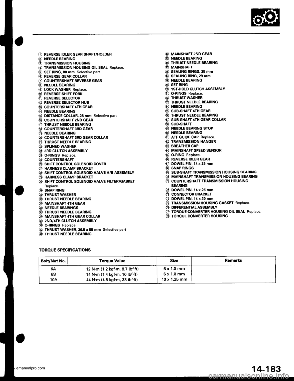
oatl,6
@!.,
ao6l
@o@@@@@o@@@)@@@@@@@@@@)
@@@@)@@@@@@@
REVERSE IDLER GEAR SHAFT,/HOLDERNEEOLE BEARINGTRANSMISSION HOUSINGTRANSMISSION HOUSING OIL SEAL R€place.SET RING,80 mm Selective part
REVERSE GEAR COLLARCOUNTERSHAFT REVERSE GEARNEEDLE BEARINGLOCK WASHER Replace.REVERSE SHIFT FORKREVERSE SELECTORREVERSE SELECTOR HUBCOUNTERSHAFT 4TH GEARNEEDLE BEARINGDISTANCE COLLAR,28 mm Selective pan
COUNTERSIIAFT 2ND GEARTHRUST NEEDLE BEARINGCOUNTERSHAFT 3RD GEARNEEDLE AEARINGCOUNTERSHAFT 3RD GEAR COLLARTHRUST NEEOLE BEARINGSPLINEO WASHER3RD CLUTCH ASSEMBLYO-RINGS Replace.COUNTERSHAFTSHIFT CONTROL SOLENOID COVERHARNESS CLAMP BRACKETSHIFT CONTROL SOLENOID VALVE A/B ASSEMBLYHARNESS CLAMP BRACKETSHIFT CONTROL SOLENOID VALVE FILTER/GASKETReplace.SNAP RINGTHRUST WASHERTHRUST NEEDLE BEARINGMAINSHAF ,ITH GEARNEEDLE BEARINGSTHRUST NEEDLE BEARINGMAINSHAFT 4TH GEAR COLLAR2ND/4TH CLUTCH ASSEMBLYO-RINGS ReDlace.THRUST WASHER,36.5 x 55 mm Selective part
THRUST NEEDLE BEARING
MAINSHAFT 2ND GEARNEEDLE BEARINGTHRUST NEEOLE BEARINGMAINSHAFTSEALING RINGS,35 mmSEALING RING. 29 mmNEEDLE BEARINGSET RINGlST-HOLD CLUTCH ASSEMSLYO-RINGS Replace.THRUST WASHERTHRUST NEEDLE BEARINGNEEDLE BEARINGSUB.SHAFT 4TH GEARTHRUST NEEDLE BEARINGSU&SHAFT,ITH GEAR COLLARSUB.SHAFTNEEDLE BEARING STOPNEEDLE BEARINGATF GUIDE CAP Replace.TRANSMISSION HANGERBREATHER CAPMAINSHAFT SPEED SENSORO-RING Reolace.REVERSE IDI.fR GEARDOWEL PlN, lil x 25 mmSNAP RINGSSU&SHAFT TRANSMISSION HOUSING AEARINGMAINSHAFT TRANSMISSION HOUSING BEARINGCOUNTERSHAFT TNANSMISSION HOUSINGBEABINGDOWEL PlN, 14 x 25 mrnCONNECTOR BRACKETDOWEL PlN, 14 x 20 mmTRANSMISSION HOUSING GASKET Replace.DIFFERENTIAL ASSEMBLYTOROUE OONVERTER HOUSING OIL SEAL Replace.TOROUE CONVERTER HOUSING
@@@@@@@@@@@@@@@@@@@@@@@)@@@@@@@
@@@@@@@
TOROUE SPECIFICATIONS
Boli/Nut No.Torque ValueSizeRemarks
6B
10A
12 N.m (1.2 kgf.m,8.7 lbf.ft)'14 N.m (1.4 kgim, 10 lbf'ft)
44 N.m (4.5 kgim, 33 lbf.ft)
6x 1.0 mm
6x1.0mm
10 x '1.25 mm
14-1A3
www.emanualpro.com
Page 702 of 1395
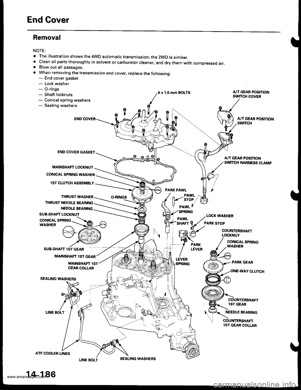
End Cover
Removal
NOTE:
o The illustration shows the 4WD automatic transmission; the 2WD is similar.. cleanall parts thoroughly in solvent or carburetor cleaner, and drythem with compressed air.. Blow out all passages.
. When removing the transmission end cover, replace the following:- End cover gasket- Lock washer- O-rings- Shaft locknuts- Conical spring washers- Sealing washers
END COVER GASKET
MAINSHAFT LOCKNUT
CONICAL SPRING WASHER
6 x 1 .0 rhm EOLTS
PARK PAWL
A/T GEAR POSMONSwlTCH COVER
NEEDI.T BEARING
SUB.SHAFT LOCKNUT
CONICAL SPRINGWASHER
LINE AOLT
ATF COOI.f B LINES
14-186
PAwL 7// Locx wASHER
'sHAFr 9/ ?ARK srop
o-- Ay' couNTERsHAFr
G-€ LocKNUr!€ / ..t,"o, "oo
A/T GEAR POSMONSW|TCH HARNESS CLAMP
CONICAL SPRINGWASHCR
A/T GEAR POSITION
PARK GEAR
Y CLUTCH
lST GEAR
NEEDLE BEARING
1ST CLUTCH ASSEMBLY
THRUST WASHER
THRUST NEEDLE AEARING
O.RINGS
\\
SUB.SHAFT 1ST GEAR
MAINSHAF? 'ST GEAR
MAINSHAFT 1STGEAR COLLAR
SEALING WASHERS
!€'-l
I"EVERSPRING
COUNTERSHAFTlST GEAR COLLAR
PAWL
lt1/ sroe
Y plwl f
L/'SPRING
LOCKNUT
LINE BOLTSEALING WASHERS
www.emanualpro.com