Manifold HONDA CR-V 1998 RD1-RD3 / 1.G Owner's Manual
[x] Cancel search | Manufacturer: HONDA, Model Year: 1998, Model line: CR-V, Model: HONDA CR-V 1998 RD1-RD3 / 1.GPages: 1395, PDF Size: 35.62 MB
Page 279 of 1395
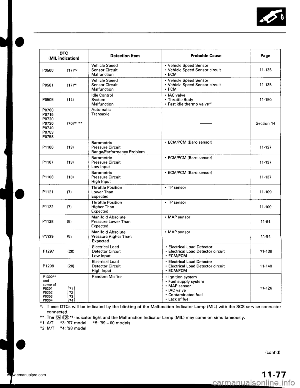
DTC(MlL indicationlDotection ltomProbable CausePage
P0500 t17)*,
Vehicle SpeedSensor CircuitMalfunction
Vehicle Speed SensorVehicle Speed Sensor circu itECtVI1 1-135
P0501 l17J*1
Vehicle SpeedSensor CircuitMalfunction
Vehicle Speed SensorVehicle Speed Sensor circuitPCM11-135
P0505 (14)ldle ControlSystemMalfunction
IAC valveThrottle BodyFast idle thermo valve*11 '�]- 150
P0700P0715PO720P0730P0740P0753P0758
AutomaticTransaxle
Section l4
P1106 (13)BarometricPressure CircuitRange/Performance Problem
ECM/PCM (Baro sensor)
11-137
P1107 (13)BarometricPressure CircuitLow InPut
. ECM/PCM {Baro sensor)11-137
P1108 (13)BarometricPressure CircuitHigh Inpur
ECM/PCM {Baro sensor)11,137
P1121 (7)Throttle PositionLower ThanExpected
. TP sensor11-109
P1122 (7)Throttle PositionHigher ThanExpected
' TP sensor1 1-'109
P112a (5)Manifold AbsolutePressure Lower ThanExpected
. MAP sensor11-94
P1129 (5)Manifold AbsolutePressure HiqherThanExpected
' MAP sensor1l-94
P1297 (20)Electrical LoadDetector CircuitLow Input
Electrical Load DetectorElectrical Load Detector circuitECM/PCM1 1- 138
P1298 (20)Electrical LoadDetector CircuitHigh Input
Electrical Load DetectorElectrical Load Detector circuitECM/PCM11-140
P1300'3
P0301P0302P0303P0304
7l721314
Random lvlisfirelgnition systemFuel supply systemMAP sensorIAC valveContaminated fuelLack offuel
11-126
*: These DTCS will be indicated by the blinking of the Malfunction Indicator Lamp {MlL} with the SCS service connector
connected.**:The E (E])+s indicator light and the Malfunction Indicator Lamp (MlL) may come on simultaneously.*1:A,./T "3: '97 model +5: '99 - 00 models*2: M/T *4:'98 model
{cont'd)
11-77
www.emanualpro.com
Page 282 of 1395

PGM-FI System
System Description
INPUTS
CKP/TDC/CYP Sensor
CKF Sensor
MAP Sensor
ECT Sensor
IAT Sensor
TP Sensor
Primary HO2S
Secondary H02S
vss
KS*5
BARO Sensor
ELD*6
Starter Signal
ALT FR Signal
Air Conditioning Signal
Ay'T Gear Position Signal*1
Baftery Voltage (lGN.1)
Brake Switch Signal
PSP Switch Signal
Fuel Tank Pressuae Sensor*4. *5
Countershaft Speed Sensor*1
Mainshaft Speed Sensor*r
OVER-DRIVE Switch Signal*s
ENGINE CONTROL MODULE (ECM)/
POWERTRAIN CONTROL MODULE (PCM) OUTPUTS
|iuel 1"j""- Th,rhg ""d Drrafr";-l
Et*-.nt"tdt"cont.orl
to,r*,c;;trffi;]
l.----.---:. .Lrgnrnon |lmrng Lonrror I
Ecir/PcM B*k',p Fr""il]
m;"t-ll-r*'io*l
Fuel Injectors
PGM-Fl Main Relay (Fuel Pump)
MIL
IAC Valve
Ay'C Compressor Clutch Relay
Radiator Fan Relay
Condenser Fan Relay
ALT
tcM
EVAP Purge Control Solenoid
Valve
Primary HO2S Heater
Secondary H02S HeaterEVAP Bypass Solenoid Valve*a *5
EVAP Control Canister Vent Shut
DLC
Lock-up Control Solenoid Valve*l
Shift Control Solenoid Valve*1
Ay'T Clutch Pressure Control
Solenoid Valve*1
D4 Indicator Light'1 *3, *a
D Indicator Light,l *5
OVER-DRIVE OFF Indicator
Lighl*t *:
*1: A/T {3:'97 model'2: M/f +4:'98 model*5: '99 - 00 models"6: USA
PGM-Fl System
The PGM-Fl system on this model is a sequential multiport fuel injection system.
Fuel iniecior Timing and Duration
The ECM/PCM contains memories for the basic discharge durations at various engine speeds and manifold pressure. The
basic discharge duration, after being read out from the memory, is further modified by signals sent from various sensors
to obtain the final discharge duration.
ldle Air Control
ldle Air Control Valve (lAC Valve)
When the engine is cold, the Ay'C compressor is on, the transmission is in gear, the brake pedal is depressed, the P/S load
is high, or the alternator is charging, the ECM/PCM controls current to the IAC Valve to maintain the correct idle speed.
lgnition Timing Control
o The ECM/PCM contains memories for basic ionition timing at various engine speeds and manifold air flow rates.
lgnition timing is also adjusted for engine coolant temperature.
. A knock control system was adopted which sets the ideal ig nition timing for the octane rating of the gasoline used.*s
Other Control Funstions
1. Starting Control
When the engine is started. the ECM/PCM provides a rich mixture by increasing fuel injector duration.
2. Fuel Pump Control
. When the ignition switch is initially turned on (ll). the ECMiPCM suppli€s ground to the PGM-FI main relay that
supplies current to the fuel pump for two seconds to pressurize the fuel system.
. When the engine is running, the ECM/PCM supplies ground to the PGM-FI main relay that supplies current to the
fuel oumo.
. When the engine is not running and the ignition is on, the ECM/PCM cuts ground to the PGM-FI main relay which
cuts current to the fuel pump.
1 1-80
www.emanualpro.com
Page 292 of 1395
PGM-FI System
Manifold Absolute Pressure (MAPI Sensor
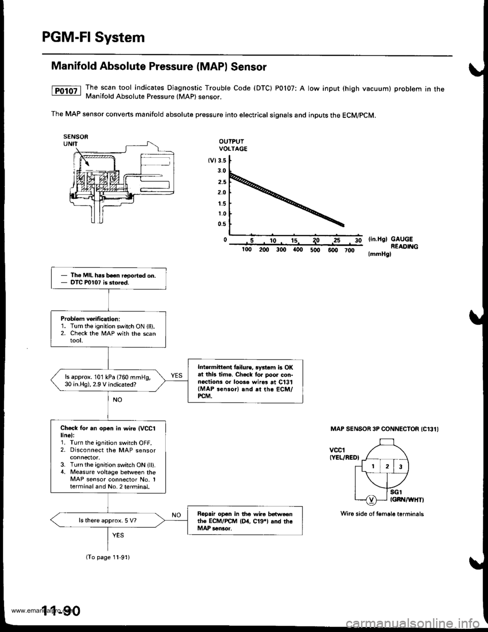
The scan tool indicates Diagnostic Trouble Code (DTC) POl07: A low input (high vacuum) problem in theManifold Absolute Pressure (MAP) sensor,
The MAP sensor convens manifold absolute pressure into electrical signals and inputs the ECM/pCM.
OUTPUIVOLTAGE
tvl3.s
3.0
2.5
2.O
1.5
1.0
0.5
o .5 ro- 15^ 1olin.H9) GAUGEREADIT{G
lmmHgl
3025
100 200 300 a00 5oo 6fi, 7d)
MAP SENSOR 3P CONNECTOR IC131I
vccl(YEL/RED}
Th6 MIL has b€en reoorted on.DTC P0107 is 3tored.
Problom verification:1. Turn the ignition switch ON lll).2. Check the lvlAP with the scanroot.
lrtormittem tailu.e, lystam b OKat thb timo. Check tor poor con-noctions or loosa wird at C131(MAP rensor) and rt the ECM/PCM.
ls approx. 101 kPa (760 mmHg,30 in.Hg),2.9 V indicated?
Check for an op6n in wi.o IVCC1linel:1. Turn the ignition switch OFF.2. Disconnect the MAP sensorconnector,3. Turn the ignition switch ON {ll}.4. Measure voltage between theMAP sensor connector No. 1termanal and No. 2 terminal.
Roprir op€n in the wir6 bstweentho ECM/PCM (D4, C19*l and theMAP sensor.
ls there approx. 5 V?
(To page 11-91)
11-90
Wiro side ol temale terminals
www.emanualpro.com
Page 294 of 1395
![HONDA CR-V 1998 RD1-RD3 / 1.G Owners Manual
PGM-FI System
Manifold Absolute Pressure (MAP) Sensor (contd)
[tn,t nn-] The scan tool indicates Diagnostic Trouble Code (DTC) P0108: A high voltage (low vacuum) problem in the|jg Manifold Absolute HONDA CR-V 1998 RD1-RD3 / 1.G Owners Manual
PGM-FI System
Manifold Absolute Pressure (MAP) Sensor (contd)
[tn,t nn-] The scan tool indicates Diagnostic Trouble Code (DTC) P0108: A high voltage (low vacuum) problem in the|jg Manifold Absolute](/img/13/5778/w960_5778-293.png)
PGM-FI System
Manifold Absolute Pressure (MAP) Sensor (cont'd)
[tn,t nn-] The scan tool indicates Diagnostic Trouble Code (DTC) P0108: A high voltage (low vacuum) problem in the|jg Manifold Absolute Pressure (MAP) sensor.
MAP SENSOR 3P CONNECTOR IC131I
Wire side of female terminals
vcclIYEL/RED}
PCM CONNECTOR D I16PI
JUMPER WIRE
sGlIGRN/WHTI
Wire side of lemale termin6ls
1
(To page 11,93)': '98 - 00 models
1-92
tcRN/wHrll IIRED/GRN|
The MIL has boen reported on.DTC m108 is slored.
Problem veritication:1. Start the engine. Hold theengine at 3,000 rpm with noload (in Park or neutral) untilthe radiator fan comes on, thenlet it idle.2. Check the MAP with the scantool.
Intermittent tailuro, system i3 OKat this time. Check tor ooor con-nections or loose wires at C131IMAP s6nsor) snd the ECM/rcM.
ls 101 kPa {760 mmHg,30 in.Hg),2.9 V or higher indicated?
Check Ior an open in the MAPsensor:1. Turn the ignition switch OFF.2. Disconnect the MAP sensor3P connector.3. lnstall a jumper wire betweenthe MAP sensor 3P connectorterminals No.3 and No.2.4. Turn the ignition switch ON {ll).5. Check the MAP with the scantool.
ls 10'l kPa (760 mmHg,30 in.Hg),2.9 V or higher indicated?
Check for an open in wire (SGlliDel:1. Remove the jumper wire.2. Measure voltage between theMAP sensor 3P connector ter-minals No. 1 and No- 2.
R6p.ir open in the wire betwoenthe ECM/PCM (D12, CTrl and theMAP sensor.
ls there approx. 5 V?
Check for an open in the wire(MAP line):1. Turn the ignition switch OFF.2. lnstall a iumper wire on thePCM connectors between D3and D12.3. Turn the ignition switch ON (ll).4. Check the MAP wirh the scantool.
Ropair opon in the wire betweenthe PCM {D3, .nd the MAP son-3('t.
ls 101 kPa 1760 mmHg, 30 in.Hg),2.9 V or higher indicated?
YES
www.emanualpro.com
Page 296 of 1395
PGM-FI System
Manifold Absolute Pressure (MAP) Sensor (cont'dl
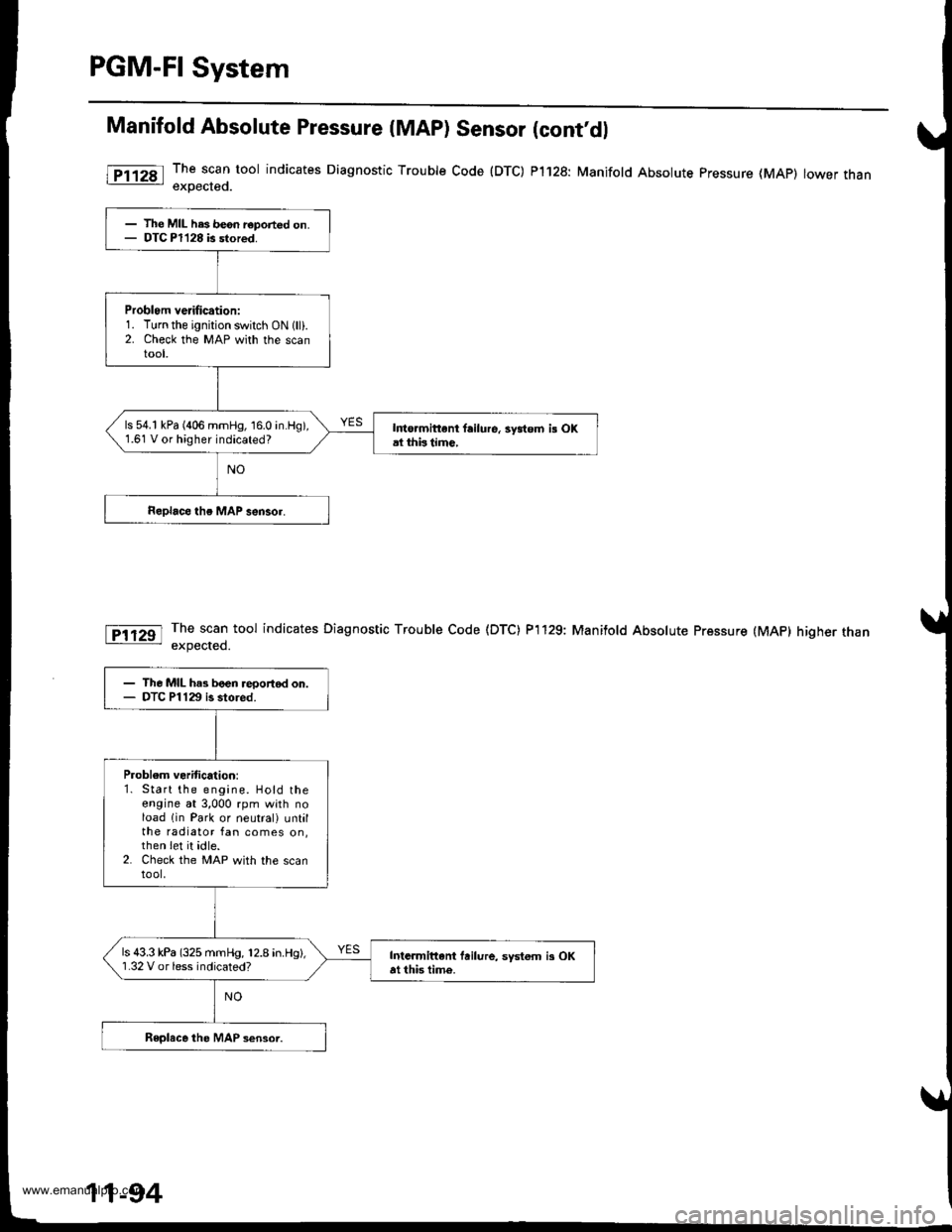
The scan tool indicates Diagnostic Trouble Code (DTC) P1128: Manifold Absolute pressure (MAp) lower thanexoected.
The scan tool indicates Diagnostic Trouble Code (DTC) P'l129: Manifold Absolute Pressure (MAP) higher thanexpected.
l
- The MIL has be6n r€ported on.- DTC Pl128 is stored.
Problom verification:1. Turn the ignition switch ON 1lli.2. Check the MAP with the scantool,
ls 54.1 kPa (406 mmHg, 16.0 in.Hg),1.61 V or higher indicated?I to.mittent failure, 3ydom i! OKal thbtimc,
- The MIL has boen reportod on.- DTC Pl129 is stored.
Problem veritication:1. Start the engine. Hold theengine at 3,000 rpm with noload lin Park or neutral) untilthe radiator fan comes on,then Iet it idle.2. Check the MAP with the scantool,
ls 43.3 kPa (325 mmHg, 12.8 in.Hg),'1.32 V or less indicated?Intarmittani fuilure, systom i3 OKat this time.
11-94
www.emanualpro.com
Page 327 of 1395
Troubleshooting Flowchart
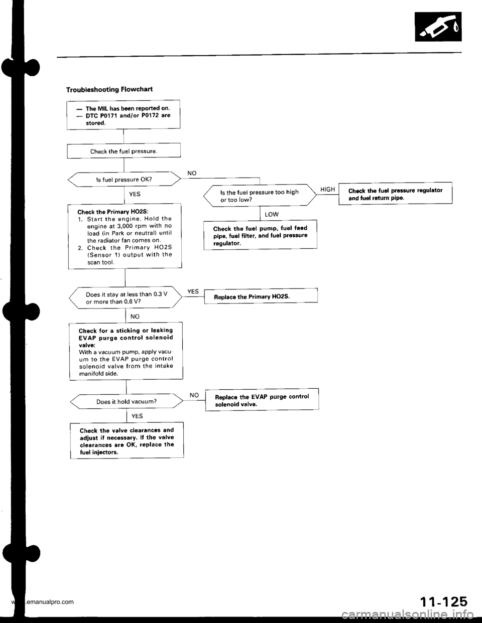
- The MIL has been rePorted on- DTC P0171 andlot P0172 are
stored,
Check the lu6l pressuro regulator
and tusl relum PiPe.ls the lLrel pressure too high
Check lhe Primaty HO2S:1. Start the engine. Hold the
engine at 3,000 rpm with no
load (in Park ot neutral) until
the radiator fan comes on
2. Check the Primary HO2S(Sensor 1) outPut with the
scan tool.
Check lh€ fuel pumP. fuel faedpipe. fuel fiher, and luel Prossurc.eguhior.
Does it stay at lessthan 0.3 V
or more than 0.6 V?
Check for a sticking or leaking
EVAP purge control solenoid
With a vacuum pump, aPPIY vacu
um to the EVAP Purge control
solenoid valve from the intake
manifold side.
Does it hold vacuum?
Check th6 valve clearanc€s and
adjust il necessary. It the valv€
clearances are OK, replace the
fuel iniectors.
www.emanualpro.com
Page 351 of 1395
ldle Control System
System Description
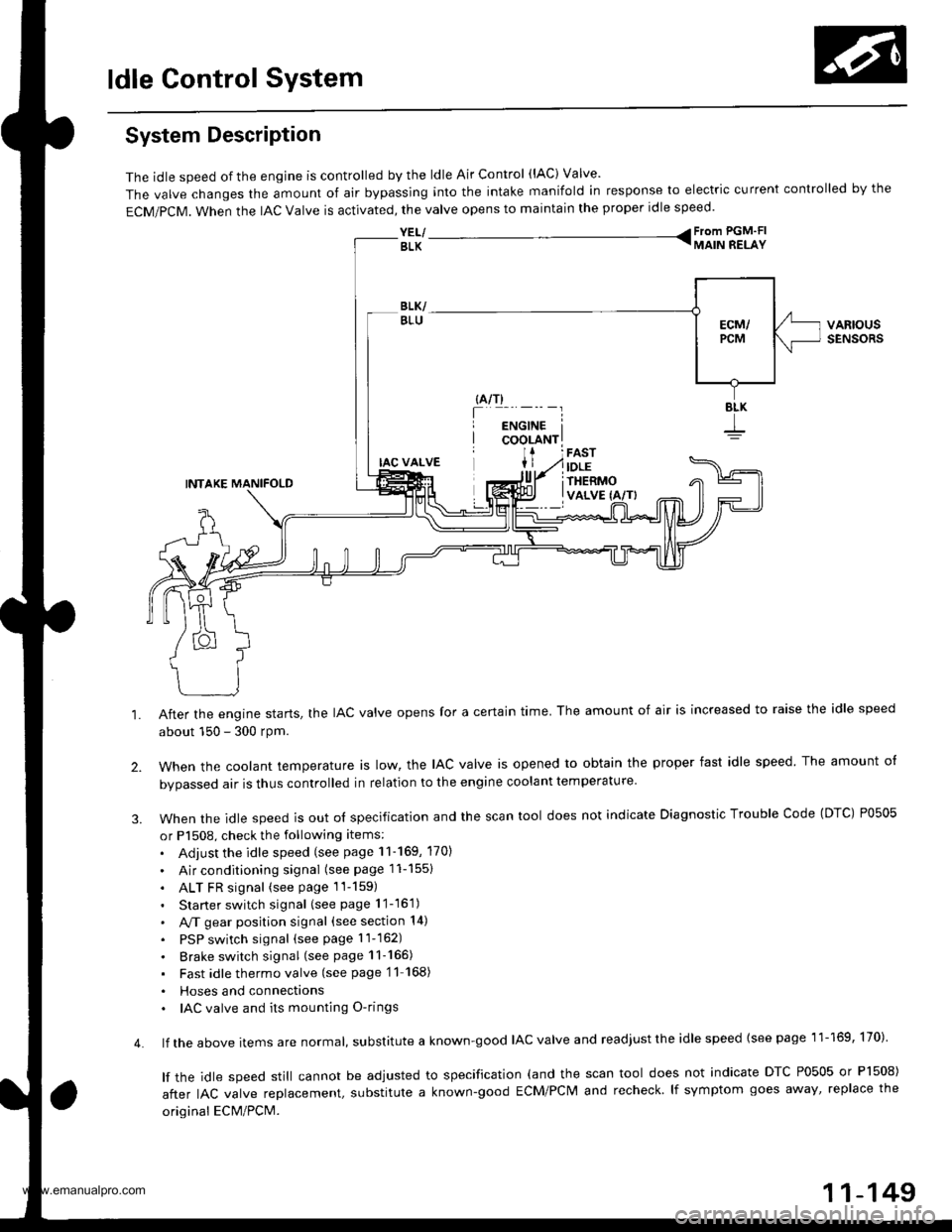
The idle speed of the engjne is controlled by the ldle Air Control (lAC) Valve'
The valve changes the amount of air bypassing into the intake manifold in response to electric current controlled by the
ECM/PCM. When the lAc valve is activated, the valve opens to maintain the proper idle speed.
YEL/ From PGM'FI
BLK TMAIN RELAY
VARIOUSSENSORS
4.
IAC VALVE
INTAKE MANIFOLD
After the engine starts, the IAC valve opens for a certain time. The amount of air is increased to raise the idle speed
about 150 - 300 rpm.
when the cootant temperature ts row, the lAc valve is opened to obtain the proper fast idle speed The amount o{
bvoassed air is thus controlled in relation to the engine coolant temperature
When the idle speed is out o{ specification and the scan tool does not indicate Diagnostic Trouble Code (DTC) P0505
or P1508, check the following items:
. Adjust the idle speed (see page 11-169, 170)
. Air conditioning signal (seepagell-1551
. ALT FR signal (see page 1l-159)
. Starter switch signal (see page 11-16'1)
. A,/T gear position signal (see section 14)
. PSP switch signal (seepagell-162)
. Brake switch signal (see page 11-165)
. Fast idlethermovalve (see page'11 168)
. Hoses and connecttons. IAC valve and its mounting O-rings
lf the above items are normat, suDslitute a known-good IAC valve and readjust the idle speed {see page 11-169, 170)
lf the idle speed still cannot be adjusted to specification (and the scan tool does not indicate DTC P0505 or Pl508)
after IAC valve reolacement, substitute a known-good ECM/PCM and recheck lf symptom goes away' replace the
original ECM/PCM.
11-149
www.emanualpro.com
Page 352 of 1395

ldle Control System
ldle Control System
I P0505 | The scan tool indicates Diagnostic T.ouble Code (DTCI PO5O5: ldlecontrol svstem mattunction.
NOTE: lf DTC P1508 is stored at the same time as DTC P0505, troubleshoot DTC P1508 first. then troubleshoot DTC p0505.
Possibls Cause
. IAC valve mechanical malfunction. Throttle body clogged port, improper adlustment. Intake manifold gasket leakaging. Intake air hose loose leakaging. Vacuum hose leakaging
a ECT sensor incorrect output. Throttle Position sensor incorrect output
Troubleshooting Flowchart
The MIL has been reDorted on.DTC P0505 is sto.ed.
Problem verificationi1. Start the engine. Hold theengine at 3,000 rpm with noload (in Park or neutral) untilthe radiator Ian comes on, thenlet it idle.2. With the scan tool, check thelollowing items.- Throttle position should beapprox. 10% with the throt-tle {ully closed.- Engine coolant temperature shorJld be 194 - 205'F(90 - 96"C).lf they are not within thespec., repair the faulty sen-sor circuit.3 Check the engine speed atidle with no-load conditions:headlights, blower fan. reardefogger, radiator lan, and airconditioner are not operaling,
Inte.mittent failure. syltem is OKat this time.ls it 750 {730)* i 50 rpm?
ls il 700 (680)' rpm or less?
{To page 11-151)(To page 1'l-151)
l:'99 - 00 models
www.emanualpro.com
Page 354 of 1395
ldle Control System
ldle Air Control llAC) Valve
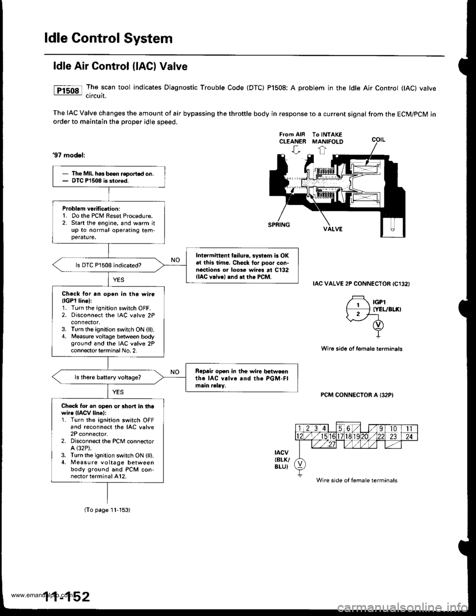
The scan tool indicates Diagnostic Trouble Code (DTC) Pl508: A probtem in the ldle Air Controt flAC) varvecircuit.
The IAC Valve changes the amount of air bypassing the throttle body in response to a current signal from the ECM/PCM inorder to maintain the proper idle speed.
37 model;
IAC VALVE 2P CONNECTOR {C132}
,f rcp'# IYEL/BI.(II2f-1-d)
Y
Wir€ side of female terminals
PCM CONNECTOR A I32PI
tacvIBLK/BLU)
From AIR To INTAKECLEANER MANIFOLD
Wire side of female terminals
The MIL has beon .eport€d on.OIC Pl508 is sto.ed.
Problem veiification:1. Do the PCM Reset Procedure.2. Start the engine, and warm itup to normal operating tem-perature.
Inte.mittent failure, systcm b OKat thi3 time. Check tor poo. con-nections or loose wircs at C132(lAC v.lvel and at the PCM.
ls DTC Pl508 indicated?
Check lor an open in the wir6{lGPl lins}:1. Turn the ignition switch OFF.2. Disconnect the IAC valve 2Pconnector.3. Turn the ignition switch ON {ll).4. Measure voltage between bodyground and the IAC valve 2Pconnector term inal No.2.
Repair open in the wire trctwoontha IAC v!lv6 and the PGM-Flmain relly.
Chock for an opan o. short in thowi.e (lACv linel:1. Turn the ignition switch OFFand reconnect the IAC valve2P connector.2. Disconnect the PCM conneclorA (32P).
3. Turn the ignition switch ON {ll).4, Measure voltage betweenbody ground and PCM con-nector terminal A12.
{To page 1l-153)
www.emanualpro.com
Page 370 of 1395
ldle Control System
Fast ldle Thermo Valve lA/T)
Description
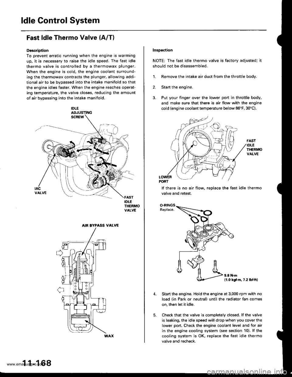
To prevent erratic running when the engine is warming
up, it is necessary to raise the idle speed. The fast idle
thermo valve is controlled by a thermowax plunger.
When the engine is cold, the engine coolant surround-
ing the thermowax contracts the plunger, allowing addi-
tional air to be bvDassed into the intake manifold so that
the engine idles faster. When the engine reaches operat-
ing temperature. the valve closes, reducing the amount
of air bypassing into the intake manifold.
IDLEADJUSTING
IDLETHERMOVALVE
AIR BYPASS VALVE
11-168
Inspgction
NOTE: The fast idle thermo valve is factory adjusted; it
should not be disassembled.
1. Remove the intake air duct from the throttle body.
2. Start the engine,
3. Put your finger over the lower port in throttle body,
and make sure that there is air flow with the engine
cold (engine coolant temperature below 86"F, 30'C).
lf there is no air flow, replace the fast idle thermo
valve and retest,
O-RINGSReplace.
11.0 kgfl.m, 7.2 lbl.ftl
Start the engine. Hold the engine at 3,000 rpm with no
load (in Park or neutral) until the radiator fan comes
on, then let it idle.
Check that the valve is completely closed. lf the valve
is leaking, the idle speed will drop when you cover the
lower pon. Check the engine coolant level and for air
in the engine cooling system {see section 10). lf the
cooling system is OK, replace the fast idle thermo
valve and recheck.
www.emanualpro.com