Rpm sensor HONDA CR-V 1998 RD1-RD3 / 1.G Owner's Manual
[x] Cancel search | Manufacturer: HONDA, Model Year: 1998, Model line: CR-V, Model: HONDA CR-V 1998 RD1-RD3 / 1.GPages: 1395, PDF Size: 35.62 MB
Page 339 of 1395
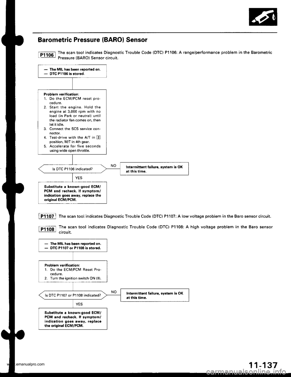
Barometric Pressure (BARO) Sensor
The scan tool indicates Diagnostic Trouble Code (DTC) P1106: A range/performsnce problem in the Barometric
Pressure {BARO) Sensor circuit.
The MIL has been reDorted on.OTC Pl106 b slored.
Problem ve.ification:1. Oo the ECM/PCM reset pro'
ceoure.2. Start the engine. Hold theengine at 3,000 rpm with noload (;n Park or neutral) untilthe radiator lan comes on, thenlet it idle.3. Connect the SCS service con-nector,4. Test'drive with the A/T in Eposition, M/T in 4th gear.
5. Accelerate Ior five secondsusing wide open throttle.
Intermittent fsilure, sy3tom i5 OKat this time.ls DTC P1106 indicated?
Substitute a known-good ECM/PCM .nd recheck. It symptom/indication goes away, replace theorigioal ECM/PCM.
fTiloz l
tP11o8l
The scan tool indicates Diagnostic Trouble Code (DTC) P1107: A low
The scan tool indicates Diagnostic Trouble Code (DTC) Pl108: A
circuit.
voltage problem in the Baro sensor circuit.
high voltage problem in the Baro sensor
- The MIL h.3 b€en roport€d on.- OTC Pl10? or Pl108 i3 stored.
Problom veritic.lion:L Do the ECM/PCM Reset Pro-cedure.2. Turn the ignition switch ON (lli.
Intarmittoni failure, lystom b OKat thb time.ls DTC P1107 or P1108 indicated?
Sub3tituto a known-good ECM/PCM and rcch6ck. ll symptom/indication 9oo3 away. .oplacorho o.igin.l ECM/PCM.
www.emanualpro.com
Page 351 of 1395
ldle Control System
System Description
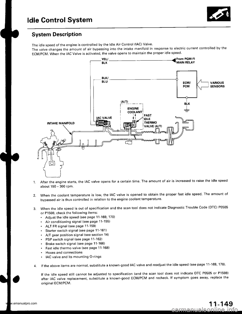
The idle speed of the engjne is controlled by the ldle Air Control (lAC) Valve'
The valve changes the amount of air bypassing into the intake manifold in response to electric current controlled by the
ECM/PCM. When the lAc valve is activated, the valve opens to maintain the proper idle speed.
YEL/ From PGM'FI
BLK TMAIN RELAY
VARIOUSSENSORS
4.
IAC VALVE
INTAKE MANIFOLD
After the engine starts, the IAC valve opens for a certain time. The amount of air is increased to raise the idle speed
about 150 - 300 rpm.
when the cootant temperature ts row, the lAc valve is opened to obtain the proper fast idle speed The amount o{
bvoassed air is thus controlled in relation to the engine coolant temperature
When the idle speed is out o{ specification and the scan tool does not indicate Diagnostic Trouble Code (DTC) P0505
or P1508, check the following items:
. Adjust the idle speed (see page 11-169, 170)
. Air conditioning signal (seepagell-1551
. ALT FR signal (see page 1l-159)
. Starter switch signal (see page 11-16'1)
. A,/T gear position signal (see section 14)
. PSP switch signal (seepagell-162)
. Brake switch signal (see page 11-165)
. Fast idlethermovalve (see page'11 168)
. Hoses and connecttons. IAC valve and its mounting O-rings
lf the above items are normat, suDslitute a known-good IAC valve and readjust the idle speed {see page 11-169, 170)
lf the idle speed still cannot be adjusted to specification (and the scan tool does not indicate DTC P0505 or Pl508)
after IAC valve reolacement, substitute a known-good ECM/PCM and recheck lf symptom goes away' replace the
original ECM/PCM.
11-149
www.emanualpro.com
Page 352 of 1395

ldle Control System
ldle Control System
I P0505 | The scan tool indicates Diagnostic T.ouble Code (DTCI PO5O5: ldlecontrol svstem mattunction.
NOTE: lf DTC P1508 is stored at the same time as DTC P0505, troubleshoot DTC P1508 first. then troubleshoot DTC p0505.
Possibls Cause
. IAC valve mechanical malfunction. Throttle body clogged port, improper adlustment. Intake manifold gasket leakaging. Intake air hose loose leakaging. Vacuum hose leakaging
a ECT sensor incorrect output. Throttle Position sensor incorrect output
Troubleshooting Flowchart
The MIL has been reDorted on.DTC P0505 is sto.ed.
Problem verificationi1. Start the engine. Hold theengine at 3,000 rpm with noload (in Park or neutral) untilthe radiator Ian comes on, thenlet it idle.2. With the scan tool, check thelollowing items.- Throttle position should beapprox. 10% with the throt-tle {ully closed.- Engine coolant temperature shorJld be 194 - 205'F(90 - 96"C).lf they are not within thespec., repair the faulty sen-sor circuit.3 Check the engine speed atidle with no-load conditions:headlights, blower fan. reardefogger, radiator lan, and airconditioner are not operaling,
Inte.mittent failure. syltem is OKat this time.ls it 750 {730)* i 50 rpm?
ls il 700 (680)' rpm or less?
{To page 11-151)(To page 1'l-151)
l:'99 - 00 models
www.emanualpro.com
Page 402 of 1395
Emission Control System
Three Way Catalytic Converter {TWCI (cont'd}
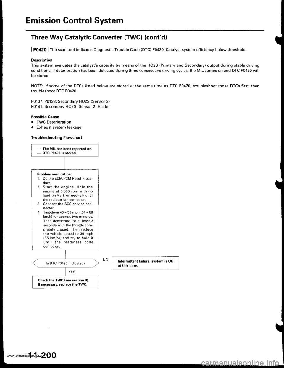
1P0420 Thescantool indicates Diagnostic Trouble Code (DTC) P0420: Catalyst system efficiency belowthreshold.
DescriDtion
This system evaluates the catalyst's capacity by means of the HO2S (Primary and Secondary) output during stable driving
conditions. lf deterioration has been detected during three consecutive driving cycles, the MIL comes on and DTC P0420 will
be stored.
NOTE: lf some of the DTCS listed below are stored at the same time as DTC P0420, troubleshoot those DTCS first. then
troubleshoot DTC P0420.
P0137, P0138: Secondary HO2S (Sensor 2)
P0141: Secondary HO2S (Sensor 2) Heater
Possible Cause
. IWC Deterioration
. Exhaust system leakage
Troubleshooting Flowchart
- The MIL has been reDoried on.- DTC P0420 is stored.
Problem verification:1. Do the ECM/PCM Reset Procedure,2. Start the engine. Hold theengine at 3,000 rpm with noload (in Park or neutrali untilthe radiator fan comes on.3. Connect the SCS service connector.4. Test-drive 40 - 55 mph (64 - 88km/h) for approx. lwo minutes.Then decelerate for at least 3seconds with the throftle completely closed. Then reducethe vehicle speed to 35 mph
156 km/h), and try to hold ituntil the readiness code
Intermittent tailure. system is OKat this time.ls DTC P0420 indicated?
Check the TWC (see section 9).lI nocessary, replace the TwC.
11-200
www.emanualpro.com
Page 407 of 1395

'97 model:
The scan tool indicates Diagnostic Trouble Code (DTC) P0441: Evaporative Emission (EVAP) control system
insufficient purge flow.
Description
By monitoring the purge line vacuum with the MAP sensor, the PCM can detect insufficient EVAP control system purge
flow.
Possiblo Cause
. EVAP Purge Control Solenoid Valve
. EVAP Purge Control Solenoid Valve Circuit
. EVAP Control Canister
. Vacuum Lines
. PCM
Troubleshooting Flowchart
EVAP PURGE CONTROL
SO1TNOID VALVE 2P
CoNNECTOR (C108)
(v)
YL
Wire side of female
termrnals
(cont'd)
11-205
Th€ MIL has b€en reooited on.DTC P0441 is .tored.
Problem verificationl1. Start the engine. Hold theengine at 3,000 rpm with noload (in Park or neut.al) untilthe radiator fan comes on.2. Do the PCM Reset Procedure.3. Connect the SCS service con-nector,4. Test drive under following con'ditions on the road.- without any electrical load- Transmission in @ or @position- Engine speed between1 ,2OO - 2,4OO rpfi.- Decelerate from 50 mph (80
km/h)to 15 mph (24 km/h)Intermittent trilure, sydern is OKat this time. Check for Door con-nections or loose wir€3 at C108
IEVAP purge control solonoidvalvol .nd at the PCM.
ls DTC P0441 indicated?
Check tor an open in the wire (lcl
linel:1. Turn the ignition switch OFF.2. Disconnect the EVAP purge
control solenoid valve 2P con-nector.3. Turn the ignition switch ON (ll).
4. Measure voltage between bodyground and the EVAP purge
control solenoid valve 2P con-nector terminal No. '1,
R€pafu open in thc wir6 b€tw€enthG EVAP purge control solenoidvalve and the No. 15 ALTEBNA-TOR SP SENSOR (7.5 A)fuse.
ls there batlery voltage?
(To page 11'206)
www.emanualpro.com
Page 594 of 1395
Electrical Troubleshooting {'97 Model)
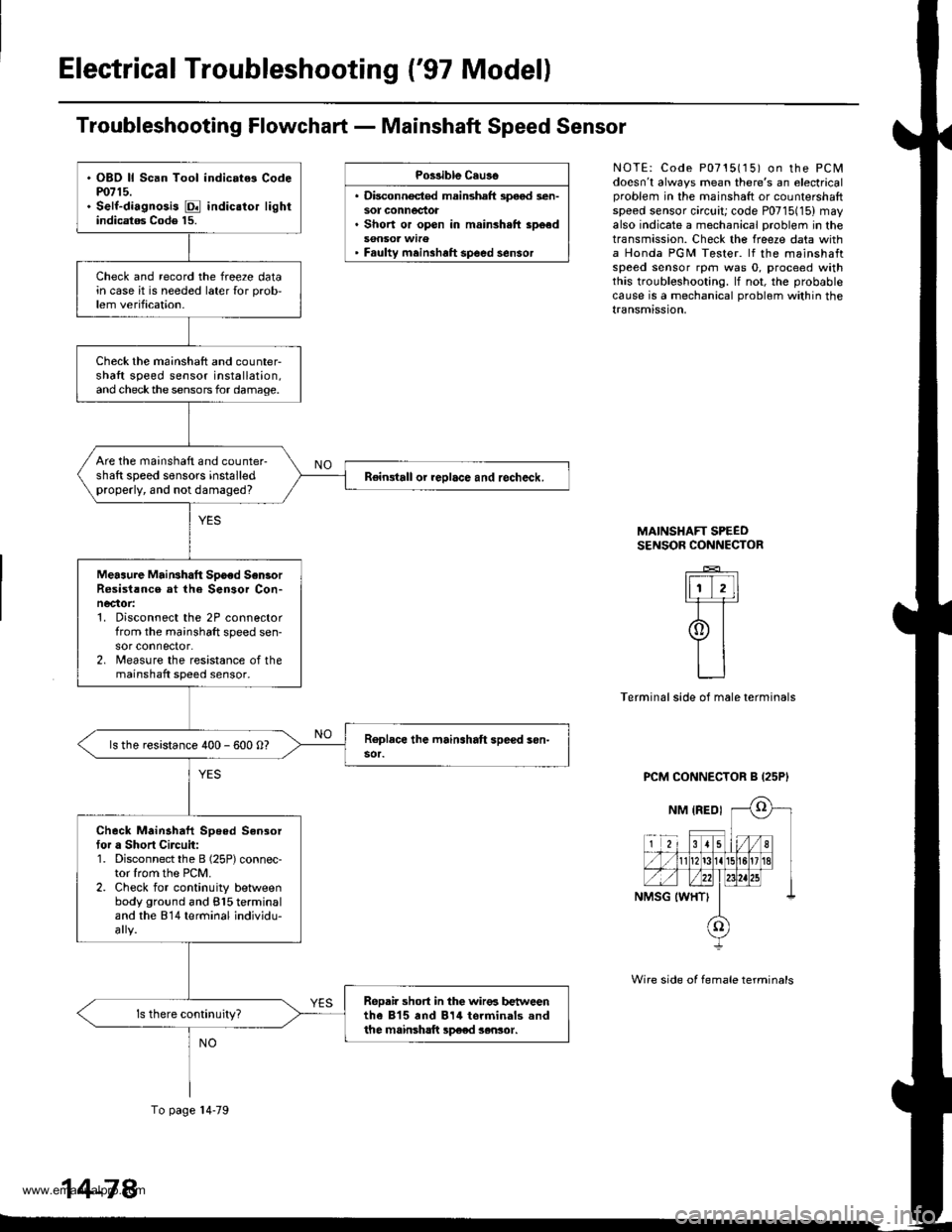
Troubleshooting Flowchart - Mainshaft Speed Sensor
Po$ible Cau3o
. Disconnocted mainshaft speod sen-sot connectot. Short or open in mainsh.ft sp6ed
' Faulty meinshaft spoed sensor
NOTE: Code P0715115) on the PCMdoesn't always mean there's an electricalproblem in the mainshaft or counlersharlspeed sensor circuit; code P0715(15) mayalso indicate a mechanical problem in thetransmission. Check the freeze data witha Honda PGM Tester. lf the mainshaftspeed sensor rpm was 0, proceed withthis troubleshooting. lf not, the probablecause is a mechanical problom within thetransmission,
MAINSHAFT SPEEOSENSOR CONNECTOR
_E_
ItiT,ll-F=r
9t
LJ
Terminal side of male terminals
PCM CONNECTOR B {25P'
Wire side of female terminals
. OBD ll Scan Tool indic.t6 Codem715.. Self-diagnosis E indic.tor lightindicatag Code 15.
Check and record the freeze datain case it is needed later {or prob,lem verification.
Check the mainshaft and counter-shaft speed sensor installation,and checkthe sensors for damage.
Are the mainshaft and counter-shaft speed sensors installedproperly, and not damaged?Reingtall or reolace and recheck.
Meaaure MaiNhatt Spoed Sen3orR6sist!nce at the Sensor Con-necaor:1. Disconnect the 2P connectorfrom the mainshaft speed sen-sor connector.2. lreasure the resistance of themainshaft speed sensor.
ls the resistance 400 - 600 O?
Check Mainahaft Speed Sensortor a Short Circuit:1. Disconnect the B (25P) connec-tor lrom the PCM.2. Check for continuity betlveenbody ground and 815 terminaland the 814 terminal individu-
ReDair short in the wir€6 b€t reenthe 815 and 814 torminals andthe mainsh!ft sp€ed sensor.
To page l4-79
14-78
www.emanualpro.com
Page 670 of 1395
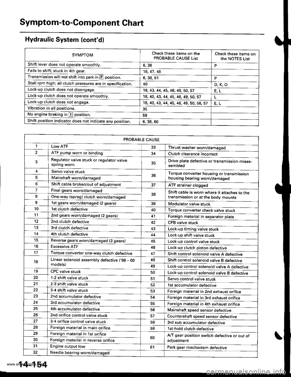
Symptom-to-Component Chart
Hydraulic System (cont'd)
SYMPTOMCheck these items on thePROBABLE CAUSE ListCheck these items onthe NOTES Lisr
Shift lever does not operate smoothly.o, JdPFails to shift; stuck in 4th gear.14, 41 , 48
Transmission will not shift into park in E position.6, 38, 61PStall rpm high; all clutch pressures are in specification.40D,K,OLock-up clutch does not disengage.18, 43, 44, 45, 46, 49,50,57
Lock-up clutch does not operate smoothly.14, 40, 43, 44, 45, 46, 49, 50. 57Lock-up clutch does not engage.'t8, 40, 43, 44, 45, 46, 49, 50, 56, 57Vibration in all positions.
No engine braking in I position.59
Shift position indicator does not indicate anv position,6. 38, 60
PROBABLE CAUSE
I 33 Thrust washer worn/damaged
ATF pump worn or binding34Clutch clearance incorrect
Regulator valve stuck or regulator valvespflng wornDrive plate delective or transmission mtsas-sembled
Servo valve stuck5ttTorque converter housing or transmissionhousing bearing worn/damagedMainshaft worn/damaged
Shift cable broken/out of adjustmentATF strainer clogged
7Final gears worn/damaged38Shift cable is worn where it attaches to thetransmission or at the body mountsIOne-way (sprag) clutch worn/damaged
1st gears worn/damaged {2 gears)39Modulator valve stuck10lst clutch defective40Torque converter check valve stuck112nd gears worn/damaged (2 gears)41Foreign material in separator plate't22nd clutch defectiveCPB valve stuck
t53rd clutch defective43Lock-up timing valve stuck144th clutch defective44Lock-up shift valve stucktcReverse gears worn/damaged (3 gears)Lock-up control valve stuck16Excessive ATF46Lock-up clutch Diston defective17Torque converter one-way clutch defective47Shift control solenoid valve A defecttve
18Linear solenoid assemblv defective (,98 - OOmodels)48Shift control solenoid valve B dsfectrve
49Lock-up control solenoid valve A defective'19CPC valve stuckLock-up control solenoid valve B deleqtve20l-2 shift valve stuck51Servo control valve stuck212-3 shift valve stuck52lst accumulator defective3-4 shift valve stuck53Foreign material in 2nd exhaust orifice2nd accumulator defective54Foreign material in 3rd exhaust orifice3rd accumulator defectiveForeign material in 4th exhaust orifice4th accumulator defective56Mainshaft speed sensor defective262nd orifice control valve stuckCountershaft speed sensor defective273-4 orifice control valve stuck583rd sub accumulator defective2aForeign material in main orifice59lst-hold clutch defective29Foreign material in lst orifice60A/T gear position switch defective or out ofadjustment30Foreign material in reverse orifice
31Engine output low61Park gear mechanism defective32Needle bearing worn/damaged
14-154
www.emanualpro.com
Page 1148 of 1395
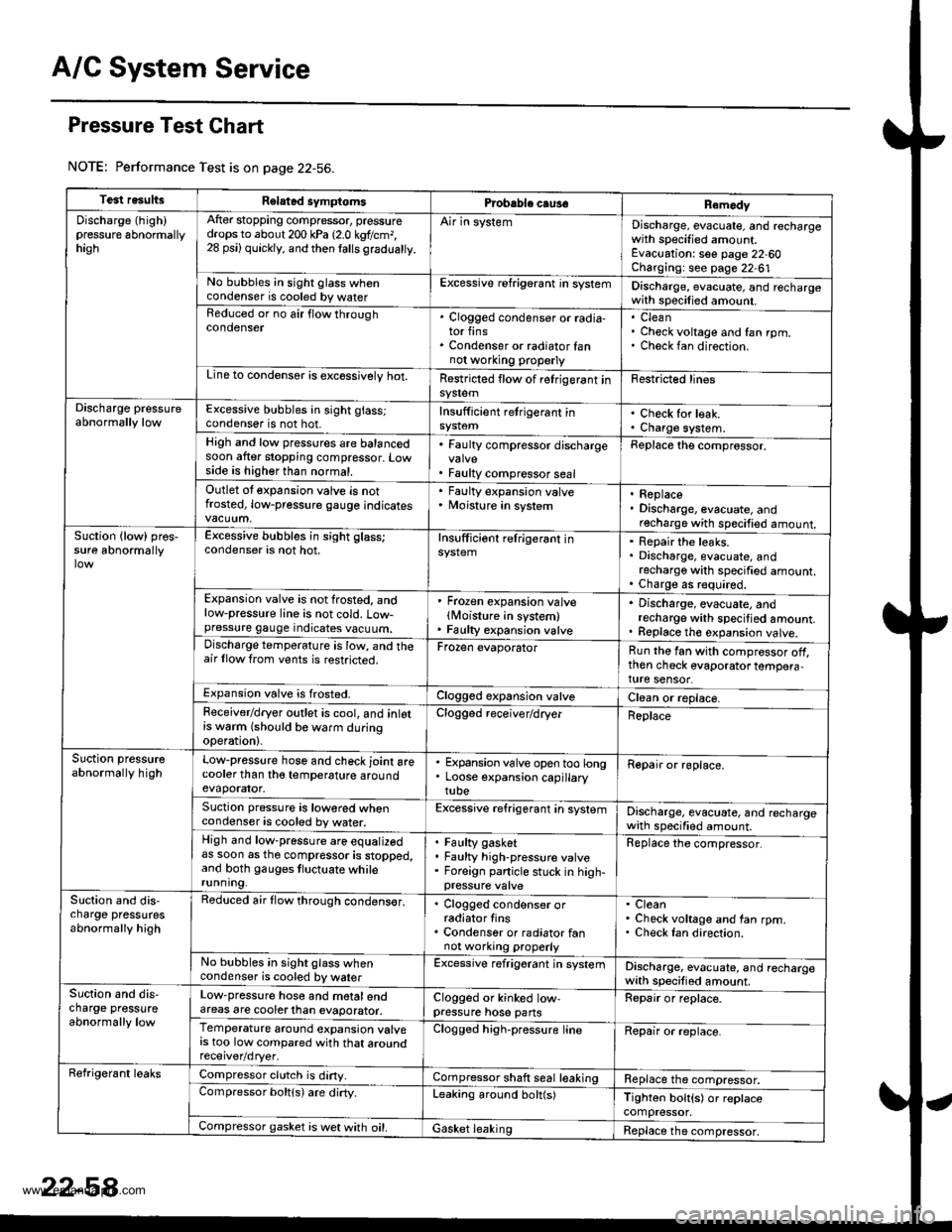
A/C System Service
Pressure Test Chart
NOTE: Performance Test is on page 22-56.
Test resultsRelatad symptomsPrcbable caus€Remody
Discharge (high)pressure 6bnormallyhagh
After stopping compressor, pressuredrops to about 200 kPa 12.0 kgtlcm,,28 psi) quickly, and then lalls gradualty.
Air in systemDischarge, evacuate, and rechargewith specified amount.Evacuation: see page 22-60Charging: see page 22-61No bubbles in sight glass whencondenser is cooled by waterExcessive refrigerant in systemDischarge, evacuate, and rechargewith specilied amount.Reduced or no air flow throughcondenser. Clogged condenser or radia-tor fins. Condenser or radiator fannot wo.king properly
CleanCheck voltage and fan rpm.Check fan direction.
Line to condensor is excossivelv hot.Restricted flow of relrigerant insy$emFestricted lines
Discharge pressureabnormally lowExcessive bubbles in sight glass;condenser is not hot.Insufficient retrigerant inCheck for leak.Charge system.High and low pressures are balancedsoon after stopping compressor. Lowside is higher than normal.
. Faulty compressor discharge
. Faulty compressor seal
Replace the comprossor.
Outlet ot expansion valve is notfrosted, low-pressure gauge indicates
' Faulty expansion valve. Moisture in system. Replace. Discharge, evacuate, andrecharge with specified amount.Suction {low) pros,sure abnormallyExcessive bubbles in sight glass;condenser is not hot.Insufficiont relrigerant inRepair the leaks.Discharge, evacuate, andrecharge with specified amount.Charge as r€quired.Expansion valve is not frosted, andlow-pressure line is not cold. Low-pressure gauge indicates vacuum.
' Frozen expansion valvelMoisture in system). Faulty expansion valve
. Discharge, evacuate, andrecharge with specitied amount.. Replace th€ expansion valve.Discharge temperature is low, and theair llow trom vents is restricted.Frozen evaporatorRun the fan with compressor off,then check evaporator tempera,ture sensor.Expansion valve is frosted.Clogged expansion valveClean or replace.Feceiver/dryer outlet is cool, and inlotrs w6rm (should be warm duringoperation).
Clogged receiver/dryerReplace
Suction pressureabnormally highLow-pressure hose and check joint arecooler than tho temperature aroundevaporator.
. Expansion valve open too long. Loose expansion capillarytube
Repair or roplace.
Suction pressure is lowored whencondenser is cooled by water.Excessive refrigerant in systemDischarge, evacuate, and rechargewath specified amount.High and low-pressure are equalizedas soon as tho compressor is stopped,and both gauges tluctuate whilerunning.
Faulty gasketFaulty high-pressure valveForeign panicle stuck in high-
Replace the compressor.
Slction and dis,charge pressutesabnormally high
Reduced air flow through condens€r,. Clogged condenser orradiator tins. Condenser or radiator fannot working properly
CleanCheck voltage and fan rpm.Check Ian direction.
No bubbles in sight glass whencondenser is cooled by walerExcessive refrigerant jn systemDischarge, evacuate, and rechargewith specified amount.Suction and dis-charge pressureabnormally low
Low-pressure hose and motalendareas are cooterlhan evaporator.Clogged or kinked low-pressure hose pansRepair or replace.
Temperature around expansion valvers too low compared with that aroundClogged high-pressure lineRepair or replace.
Refrigerant leaksCompressor clutch is diny.Compressor shaft seal leakingReplace the compressor.Compressor boltls) are dirty.Leaking around bolt(s)Tighton bolt{s) or replacecompressor.Compressor gasket is wet with oil.Gasket leakingReplace the compressor,
www.emanualpro.com
Page 1216 of 1395
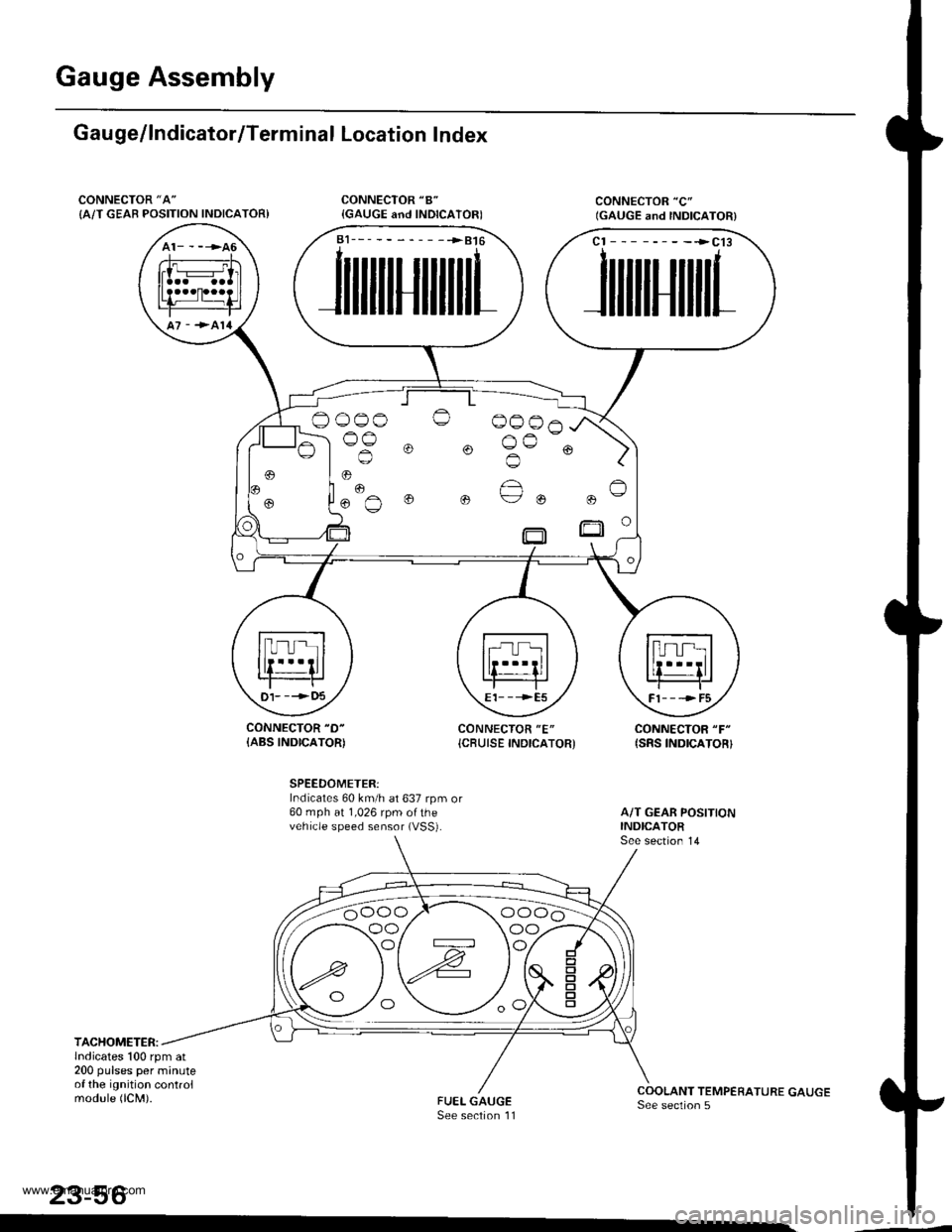
Gauge Assembly
Gau ge/lndicator/Terminal Location Index
CONNECTOR "A"
{A/T GEAB POSITION INDICATOR)
CONNECTOR "D-
{ABS INDICATOR)CONNECTOR "E"
{CBUISE INDICATOR'CONNECTOR "F"
{SRS INDICATOR}
SPEEDOMETER:Indicates 60 km/h at 637 rpm or60 mph at 1,026 rpm ofthevehicle speed sensor (VSS).
TACHOMETER:lndicates 100 rpm at200 pulses per minuteof the ignition controlmodule (lCM).
23-56
a1___-__-____>816
JilililIJililil1
cl --------->cl3
JililtHililL
,
.. "€""^
o o ue ou
t)1- --->t)5E1- - -->E5Fl---->F5
oo/ \oo
www.emanualpro.com