Scs HONDA CR-V 1998 RD1-RD3 / 1.G Owner's Manual
[x] Cancel search | Manufacturer: HONDA, Model Year: 1998, Model line: CR-V, Model: HONDA CR-V 1998 RD1-RD3 / 1.GPages: 1395, PDF Size: 35.62 MB
Page 520 of 1395
Description
General Operation (cont'dl
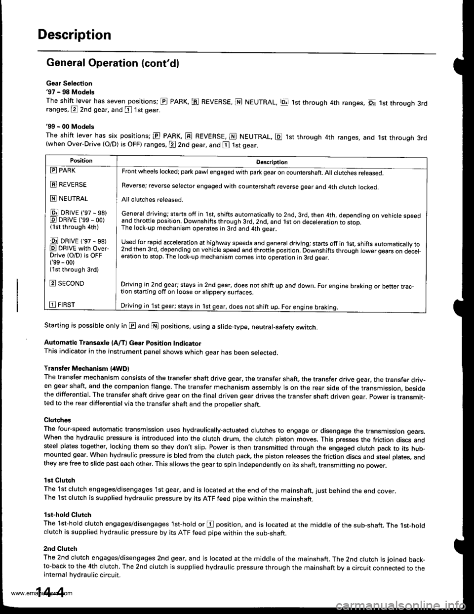
Gsar Selection'97 - 98 Models
The shift lever has seven positions; El PARK, ts REVERSE, N NEUTRAL, Ell 1st through 4th ranges, lpq 1st th.ough 3rdranges, P 2nd gear, and [ 1st gear
'99 - 00 Models
The shitt lever has six positions; El PARK, E REVERSE, E NEUTRAL. E ,lst through 4th ranges, and 1st through 3rd(when Over-Drive (O/D) is OFF) ranges. @ 2nd gear, and E 1st gear.
Starting is possible only in @ and @ positions. using a slide-type. neutral-safety switch.
Automatic Transaxle (A/T) Gear Position IndicatorThis indicator in the instrument panel shows which gear has been selected.
Transler Mochanism {4WD}
The transfer mechanism consists of the transfer shaft drive gear. the transfer shaft. the transfer drive gear, the transfer driv-en gear shaft, and the companion flange, The transfer mechanism assembly is on the rear side ot the transmission. besidethe differential. The transfer shaft drive gear on the final driven gear drives the transfer shaft driven qear. power is transmit-ted to the rear differential via the transfer shaft and the Drooeller shaft.
Clutches
The four-speed automatic transmission uses hydraulically-actuated clutches to engage or disengage the transmission gears.When the hydraulic pressure is introduced into the clutch drum, the clutch piston moves. This presses the friction discs andsteel plates together, locking them so they don't slip. Power is then transmifted through the engaged clutch pack to its hu$mounted gear. When hydraulic pressure is bled from the clutch pack, the piston releases the friction discs and steel plates, andthey are free to slide past each other. This allows the gearto spin independently on its shaft, transmitting no power.
lst Clutch
The 1st clutch engages/disengages lst gear, and is located at the end ofthe mainshaft, just behind the end cover.The 1st clutch is supplied hydraulic pressure by its ATF feed pipe within the mainshaft.
lst-hold Clutch
The 1st-hold clutch engages/disengages 1st-hold or E position, and is located at the middle of the sub-shaft. The 1st-holdclutch is supplied hydraulic pressure by its ATF feed pipe within the sub-shaft.
2nd Clutch
The znd ciutch engages/disengages 2nd gear, and is located at the middle of the mainshaft. The 2nd clutch is joined back-to-back to the 4th clutch. The 2nd clutch is supplied hydraulic pressure through the mainshaft by a circuit connected to theinternal hydraulic circuit.
PositionDescription
Reverse; reverse selector engaged with countershaft reverse gear and 4th clutch locked.
Allclutches released.
General driving; starts off in 1st, shifts automatically to 2nd, 3rd, then 4th, depending on vehicle speedand throftle position. Downshifts through 3rd,2nd, and lst on deceleration to stop.The lock-up mechanism operates;n 3rd and 4th gear.
used for rapid €cceleration at highway speeds and general driving; stans off in 1st, shifts automatically to2nd_then 3rd, dejending on vehicle speed and throttle position. Downshifts through lower gears on decel-eration to stop. The lock-up mechanism comes into operation in 3rd gear.
Driving in 2nd_gear; stays in 2nd gear, does not shift up and down. For engine braking or better trac_tion starting off on loose or slippery surfaces.
Driving in 1st gear; stays in 1st gear, does not shift up. For engine braking.
tll PARK
t!!l l|EvEn>E
E NEUTRAL
Ell DRrvE ('97 - sB)E DRrvE ('ss - oo)(1st through 4th )
E DRrvE {'97 - s8)O DRTVE with over-Drive (O/D) is OFF('99 - 00)(1st through 3rd)
E SECOND
E FIRST
14-4
www.emanualpro.com
Page 565 of 1395

PCM CONNECTOR B (25P) lcont'd)
PCM CONNECTOR C {31PI
PCM CONNECTOR D II6PI
Terminal NumbelSignalDescriptionMeasuring Conditions/Terminal voltage
811SHBShift control solenoid valve B
control
In E, E position, in 1st and 2nd gear in -q,
Er position: Battery voltage
In B position, in 3rd gear in qd, q:l,in atn
gear in D. position: 0 V
812ILUlnterlock controlWhen ignition switch is ON (ll), brake pedal
deDressed and accelerator oedal released:0 V
B13D4 INDD4 Indicator light controlWhen ignition switch is first turned ON (ll): 6 V
or more for tlvo seconds
In lDll position: 6V or more
814NMSGMainshaft speed sensor ground
815NMMainshaft speed sensor signal
InpuI
Depending on engine speed: Pulsing signal
When engine is stopped: 0 V
816ATP RAy'T gear position switch Eposition signal input
In E position; OV
In other than E position: Battery voltage
817ATP 2Ay'T gear position switch E posi-
tion signal input
InEposition:0V
In other than E position: Battery voltage
B18ATP 1A/T gear position switch El posi-
tion signal input
InEposition:0V
In other than E position: Battery voltage
819 to 821Not used
B�22NCSGCountershaft speed sensor ground
NCCountershaft speed sensor signal
Inpur
Depending on vehicle speed: Pulsing signal
when vehicle is stooped: 0 V
824ATP D4A/T gear position switch iql posi-
tion signal input
In E position: 0V
In other than lgal position: Baftery voltage
825ATP NPAy'T gear position switch E and
N position signals input
In E and E positions: 0V
In otherthan @ and ffi positions:5 V
Terminal NumberSignalDescriptionMeasuring Conditions/Terminal Voltage
SCSService check signalWith ignition switch ON (ll) and service check
connector open: 5 V
With ignition switch ON (ll) and service check
connector connected with special tool: 0 V
c10VBUBack-up power system(under-hood Fuse 47)
Always battery voltage
Terminal NumberSignalDescriptionMeasuring Conditions/Terminal Voltage
STOP SWBrake switch signal inputBrake pedal pressedr Battery voltage
Brake pedal released: 0 V
14-49
www.emanualpro.com
Page 570 of 1395

PCM Terminal Voltage/Measuring Conditions
A/T Control System -'98 - 00 Models
The PCM terminal voltage and measuring conditions are shown for the connector terminals that are related to the A"/T con-
trol system. The other PCM terminal voltage and measuring conditions are described in section 11.
FCM Connector Terminal Localions
NOTE: 819 and C3 terminalsare applied to'99 - 00 models.
o (16Pt
T6rminal NumberSignalDescriptionMeasuring Conditions/Terminal Voltage
A5CRSDownshift signal input from
cruise control unit
When cruise control is used; Pulsing signal
A10scsTiming and adjustment service
check signal (5 V from PCM)
With ignition switch ON (ll) and service check
connector open:5 V
With ignition switch ON (ll) and service check
connector jumped with special tool: 0 V
A14('98 model)
D4 INDD4 indicator light control
{Voltage from PCM turns D4 light
oN)
When ignition switch is first turned ON (ll):
Battery voltage for two seconds
In E position: Battery voltage
A14
('99 - 00 models)
D INDD indicator light control(Voltage from PCM turns D light
oN)
When ignition switch is first turned ON (ll):
Baftery voltage for two seconds
ln E position: Battery voltage
428ILUInterlock control(Voltage from PCM)
When ignition switch ON {ll), brake pedal
depressed, and accelerator pedal released:
Battery voltage
A.32STOP SWBrake switch signal inputBrake pedal pressed; Battery voltage
Brake pedal released: 0 V
FCM CONNECTOR B I25P}
Terminal NumberSignalDescriptionMeasuring Conditions/Terminal Voltage
B1IGPlPower supply circuit from main
relay via under-hood Fuse 44
With ignition switch ON {ll): Battery voltage
With ignition switch OFF: 0 V
82PG1Ground (G101)
B8LSMLinear solenoid power supply
negative electrode
IG P2Power supply circuit from main
relay
With ignition switch ON (ll): Baftery voltage
With ignition switch OFF: 0 V
810PG2Ground (G101)
B17Linear solenoid power supply
positive electrode
With ignition switch ON (ll): Pulsing signal
819
('99 - 00 models)
O/D INDOver-Drive (O/D) OFF indicator
light control
When ignition switch is first turned ON (ll):
0 V for two seconds
O/D OFF indicator light ON:0 V
O/D OFF indicator light OFF: Battery voltage
s20Ground (G101)
B�21VBUBack-up power supply(under-hood Fuse 47)
Always battery voltage
B�22LG2Ground (G101)
14-54
www.emanualpro.com
Page 573 of 1395
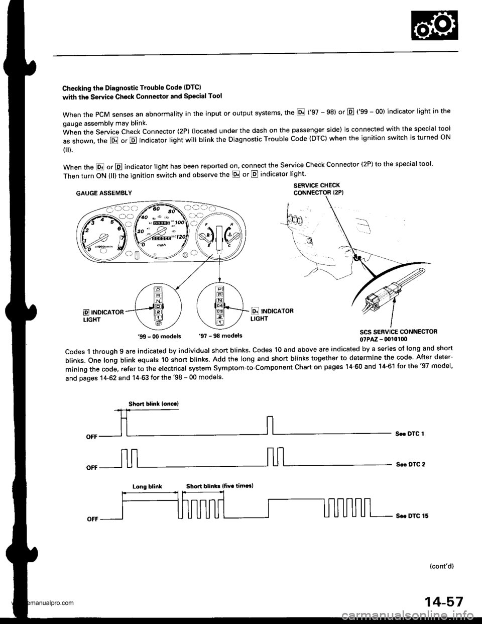
Checking the Diagnostic Trouble Code IDTCI
with the Servic€ Check Connestol and Special Tool
when the PcM senses an abnormality in the input or output systems' the E ('97 - 98) or E (gS - OO) indicator light in the
gauge assembly may blink.
When the Service Check Connector (2P) (located under the dash on the passenger side) is connected with the special tool
as shown, the E or E indicator light will blink the Diagnostic Trouble Code (DTC) when the ignition switch is turned ON
{ ).
when the E or E indicator light has been reponed on, connect the service check connector (2P) to the special tool
Then turn ON (ll) the ignition switch and observe the E or E indicator light'
.AUGE AssEMaLY $1,"^f:tT"'ff,
SCS SERVICE CONNECTOR07PAz - (x!l0100
codes 1 through 9 are indicated by individual short blinks. codes 1o and above are indicated by a series of long and short
blinks. one long blink equals 1o short blinks. Add the long and short blinks together to determine the code. After deter-
mining the code, refer to the electrical system symptom-to-component chart on pages 14-60 and 14-61 for the '97 model,
and pages 14-62 and 14-63 tor the '98 - 00 models.
Sr. DTC 1
S.. DTC 2
Long blinkShori blink! {fiv. timt l
Sc. DTC 15
(cont'd)
'99 - O0 models '97 - 98 models
Short blinl lonc.)
14-57
www.emanualpro.com
Page 603 of 1395
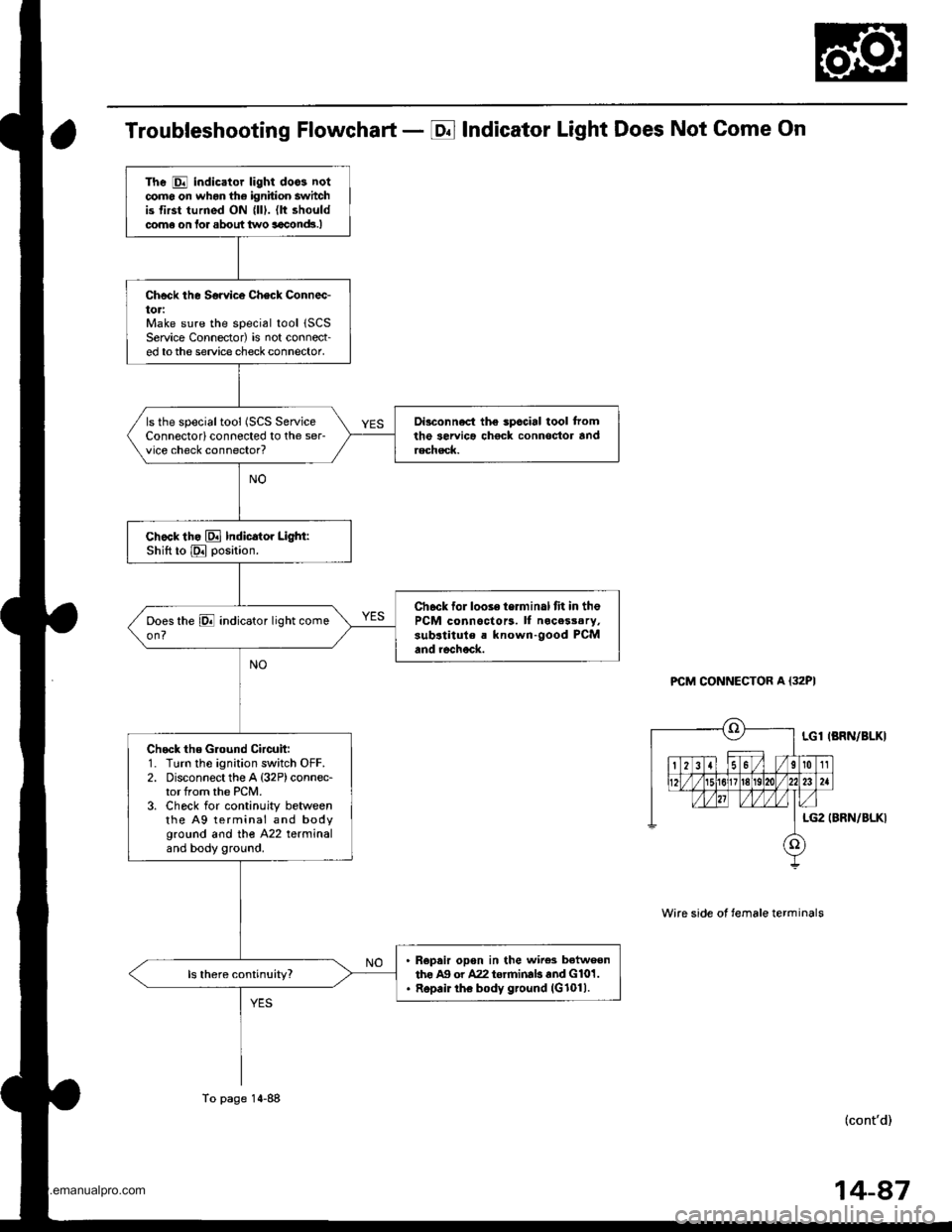
Troubleshooting Flowchart - E Indicator Light Does Not Come On
PCM CONNECTOR A {32PI
Wire side ot temale terminals
LGl IBRN/BLKI
LG2 (BRN/BLKI
(cont'd)
The E indicator light doos notcomo on whon the ignition switchis first turned ON {lll. (lt shouldcome on lor about two aaclnd!.I
Check the Sorvice Check Connec-toriMake sure the special tool 1SCSService Connector) is not connect-ed tothe service check connector,
Di3connect the spccial tool tromthe servica chock connoctor andrechsck.
ls the specialtool (SCS ServiceConnectorlconnected to the ser-vice check connector?
chock th. El Indicator Light:Shift to E position.
Ch6ck for looie terminal fit in thePCM connoctors. ll nocesssry,sub.titule a known-good PCMand rechock.
Check the Ground Circuit:1. Turn the ignition switch OFF.2. Disconnect the A {32P)connec-tor from the PCM.3. Check for continuity betweenthe A9 terminal and bodyground and tho A22 terminaland body ground.
R€pair opon in the wire3 betweenthe Ag or A22 torrninab and G101.Repair the body ground (G1011.
To page 14-88
14-87
www.emanualpro.com
Page 639 of 1395
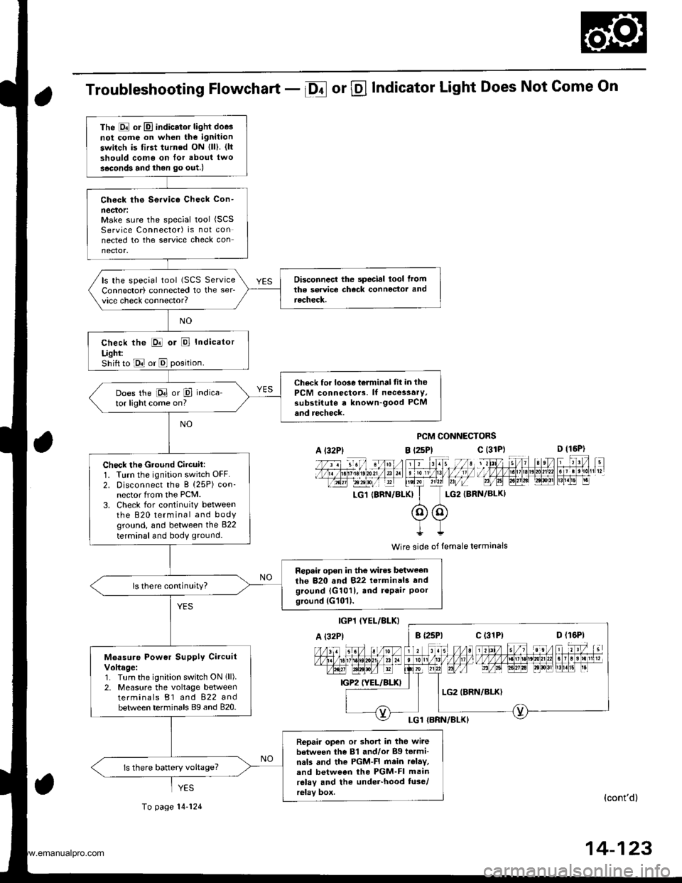
Troubleshooting Flowchart - Df or @ Indicator Light Does Not Come On
PCM CONNECTORS
B t2sPl c (31D (16P)
l*f4tr 8-
f - -- -6 3 rol ,: irr t lrpri$fe?0?r/a)1 e 'oI 13 11/ / l//|rrr I , ltelx ?r2? r,/i-T_LG1 {8RN/BI-KI I LG2 (BRN/BL()I
@@I++
Wire side of lemale terminals
(cont'd)
14-123
The E or El indicator light doe3not cofie on when the ignitaon
switch is first turned ON {ll). {ltshould como on for about two
s.cond3 and ihen go out.l
Check ths Service Check Con-
neclor:Make sure the special tool (SCS
Service Connector) is not connected to the service check connector.
Disconnecl the special lool lromtha service check connoctor andrecheck.
ls the special tool (SCS ServiceConnector) connected to the ser_vice check connector?
check the E or E Indicator
Ught:Shift to E or E position.
Check for loo3e t6lminal tit in thePCM connectors. lf necessary.substitute a known-good PCMand recheck.
Does the E or P indica-tor light come on?
Check the Gtound Circuil:1. Turn the ignition switch OFF.2. Disconnect the B (25P) con-nector from the PCM.3. Check for continuitY betweenthe 820 terminal and bodyground, and between the 822
terminal and body ground.
Repair open in the wires betweenthe 820 and 822 terminals andground {G1011, and r€Pair Poorground (G101).
ls there continuity?
Measure Power Supply CircuitVoltage:1. Turn the ignition switch ON 1ll).2. Measure the voltage betweenterminals B1 and 822 andbetween terminals Bg and 820.
Repair open or short in tho wi.ebetween the 81 and/or Bg tormi-nals and the PGM-FI main r€lay,.nd between tho PGM-FI mainrelay and the under-hood tuse/relay box.
ls there battery voltage?
A l32Plc (31P)
c (31P)
YES
To page 14-124
www.emanualpro.com
Page 729 of 1395
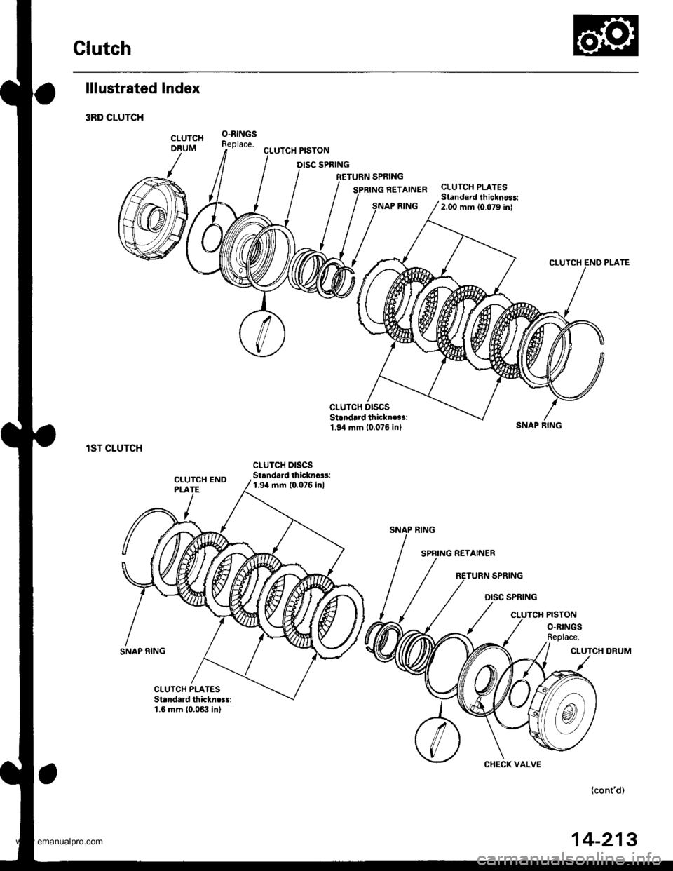
Glutch
lllustrated lndex
3RD CLUTCH
lST CLUTCH
SNAP RING
CLUTCH PISTON
RETURN SPRING
NETAINER
RING
CLUTCH PLATESStandard thicknoss:2.00 mm 10.079 inl
CLUTCH DISCSStandard thickne$:1.94 mm (0 0?6 inl
CLUTCH DISCSStandard thicknca3:1.9a mm 10.076 inl
SNAP FING
CLUTCH DRUM
(cont'd)
CHECK VALVE
14-213
www.emanualpro.com
Page 732 of 1395
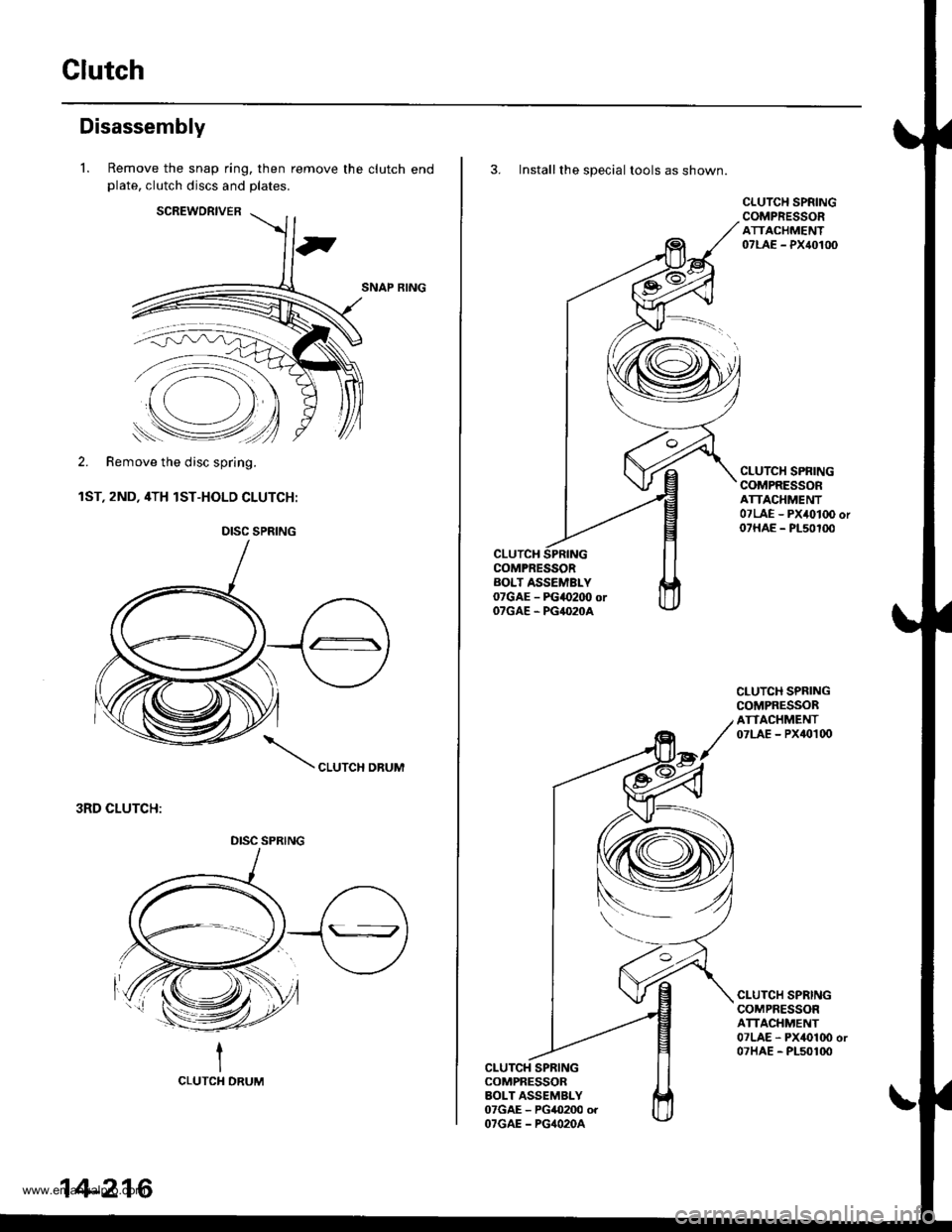
Clutch
Disassembly
l. Remove the snap ring, then remove the clutch endplate, clutch discs and plates.
SCREWORIVER
SNAP RING
2. Remove the disc spring.
1ST, 2ND, 4TH lST-HOLD CLUTCH:
CLUTCH DBUM
3RD CLUTCH:
-'=*.=:--
'..p
Remove the disc spring.
DISC SPRING
DISC SPRING
14-216
3. Install the special tools as shown.
CLUTCHCOMPRESSORAOLT ASSEMBLY07GAE - FGao2OO orOTGAE . PG4O2OA
CLUTCH SPNINGCOMPRESSORATTACHMENT07LAE - PX40100
CLUTCH SPRINGCOMPRESSORATTACHMENT07LAE - PX4010O or07HAE - PL50100
CLUTCH SPRINGCOMPRESSORATTACHMENT07LAE - PX40t00
CLUTCH SPRINGCOMPRESSORATTACHMENT07LAE - PX4010O or07HAE - PL50100
CLUTCH SPRINGCOMPRESSORBOLT ASSEMBLY07GAE - PG0200 orOTGAE - PG4O2OA
www.emanualpro.com
Page 736 of 1395
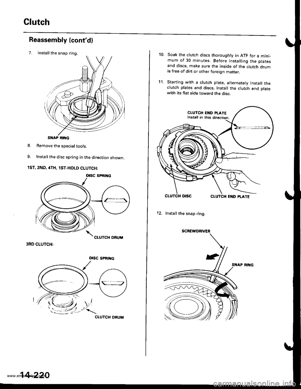
Clutch
Installthe snap ring.
Reassembly (cont'd)
7.
S AP RIIG
8. Remove the special tools.
9, Install the disc spring in the direction shown.
1ST, 2ND, 4TH, lST-HOLD CLUTCH:
3RD CLUTCH:
Dlsc sPRrrtc
CIUTCH ORUM
otsc sPfitl{c
14-220
10.Soak the clutch discs thoroughly in ATF for a mini_mum of 30 minutes. Before installing the platesand discs, make sure the inside of the clutch drumis free of din or other foreign matter
Starting with a clutch plate, alternatelv install theclutch plates and discs. Install the clutch end platewith its flat side toward the disc.
CLUTCH EI{D PI.ATEInstall in this directior.
CLUTCHCLUTCH EI{D PLATE
12. Install the snap ring.
SCREWDRIVER
't1.
www.emanualpro.com
Page 737 of 1395
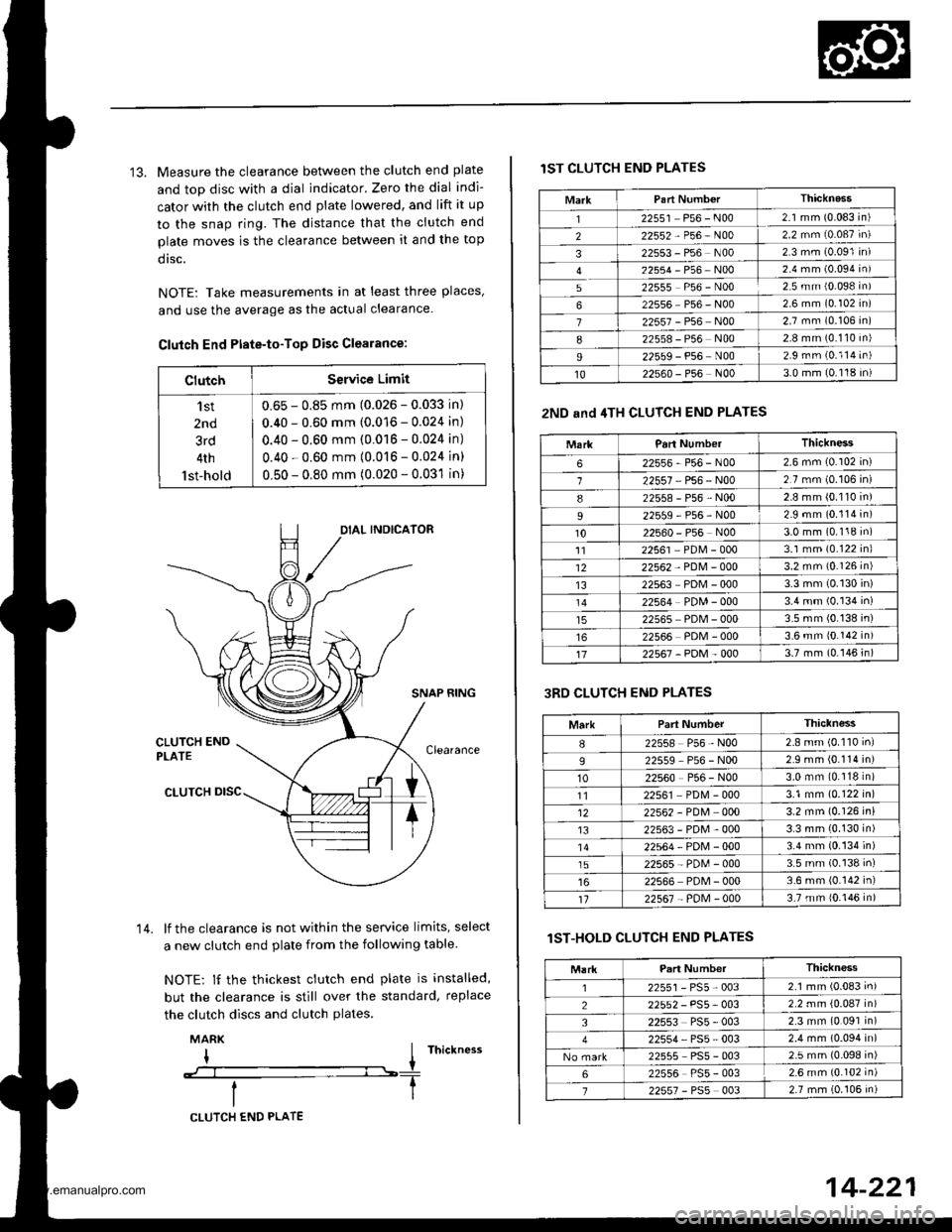
13. Measure the clearance between the clutch end plate
and top disc with a dial indicator. Zero the dial indi-
cator with the clutch end plate lowered, and lift it up
to the snap ring. The distance that the clutch end
plate moves is the clearance between it and the top
dtsc.
NOTE: Take measurements in at least three places'
and use the average as the actual clearance.
Clutch End Ptate-to-Top Disc Clearance:
ClutchService Limit
'l st
2nd
3rd
4th
lst-hold
0.65 - 0.85 mm (0.026 - 0.033 in)
0.40 - 0.60 mm (0.016 - 0.024 in)
0.40 - 0.60 mm (0.016 - 0.024 in)
0.40 - 0.60 mm (0.016 - 0.024 in)
0.50 - 0.80 mm (0.020 - 0.031 in)
SNAP RING
lf the clearance is not within the service limits, select
a new clutch end plate from the following table
NOTE: lf the thickest clutch end plate is installed,
but the clearance is still over the standard, replace
the clutch discs and clutch plates.
MARK
I I rnictness
--:--l----T
14.
CLUTCH END PLATE
14-221
lST CLUTCH END PLATES
2ND and 4TH CLUTCH END PLATES
3RD CLUTCH END PLATES
lST-HOLD CLUTCH END PLATES
MarkThicknass'I22551 P56 - N002.1 mm (0.083 in)
222552-P56-N002.2 mm (0.087 in)
322553 - P56 N002 3 mm (0.091 in)
22554-P56-NOo2.4 mm (0.094 in)
522555 P56 - N002.5 mm {0.098 in)
622556 P56 - N002 6 mm (0.102 in)
722557 - P56 N002.7 mm (0.106 in)
822558 - P56 N002.8 mm (0.110 in)
I22559 - P56 N002.9 rnm (0.114 in)
1022s60 - P56 N003.0 mm (0.118 in)
MarkParl NumberThickness
622556-P56-N002.6 mm (0.102 in)
122557 P56 - N002.7 mm (0.106 in)
822558-P56-N002.8 mm (0.110 in)
22559-P56-N002.9 mm (0.114 in)
1022560 - P56 N003.0 mm (0.118 in)'1122561 PDM - 0003.1 mm (0.122 inl
1222562 - PDM - 0003.2 mm {0.126 in)
1322563 PDM - 0003.3 mm (0.130 in)
22564 PDM - 0003.4 mm (0.134 in)
22565 PDM - 0003.5 mm (0.138 in)
22566 PDM - 0003.6 mm 10.142 in)
1722567-PDM-0003.7 mm (0.146 in)
MarkPart NumberThiclness
I22558 P56 - N002.8 mm (0.110 inl
922559 P56 - N002.9 mm (0.114 in)
1022560 P56 - N003.0 mm (0.118 in)
1122561 PD[4 - 0003.1 mm (0.122 in)
1222562 - PDM 0003.2 mm (0.126 in)
t322563-PDM-0003.3 mm (0.130 in)'1422564-PDN4-0003.4 mm (0.134 in)
1522565-PD[,l-0003.5 mm (0.138 in)
22566 PDM - 0003.6 mm (0.142 in)'t122567 - PoM - 0003.7 mm {0.146 in)
Thickness
2255r-PS5-0032.1 mm (0.083 in)
22552 - PS5- 0032.2 mm {0.087 in)
322553 PS5 - 0032.3 mm (0.091 in)
22554, PS5 - 0032.4 mm (0.094 in)
22555 PS5 - 0032.5 mm (0.098 in)
622556 PS5 - 0032.6 mm {0.102 in)
722557 - PSs 0032.7 mm (0.106 in)
www.emanualpro.com