Seat belt HONDA CR-V 1998 RD1-RD3 / 1.G Owner's Manual
[x] Cancel search | Manufacturer: HONDA, Model Year: 1998, Model line: CR-V, Model: HONDA CR-V 1998 RD1-RD3 / 1.GPages: 1395, PDF Size: 35.62 MB
Page 1225 of 1395
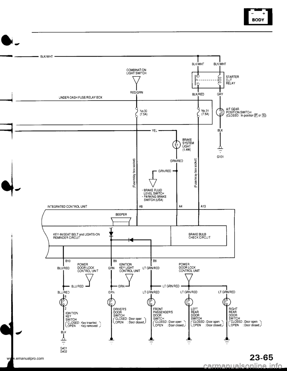
< - ELK/WHT
S'TARTEBCUTRELAY
A,/rGEARPOSrr 0N SWTTCH(CLOSED :ln postion Eor N)
COMBINATONLIGHT SWITCH
\-/
IRED/GRN
I
.l-
NTEGRATED CONTROL UNIT
POWERDOOR LOCKCONTROL UNIT
I B1o PowERBLU/RED DOOR LOCK
I CONTFOL UN T
IY
F r,r'tro J
BLUi RED
"l\
u/
llon. no*
155,1'*IaCLOSED Keylnseded
| \oPEN Key rcmoved
8LK
4
G40r
LTGRN/RED LTGRN/RED LTtl
/rh d[)v !s-l
I FFONT I LEFTI PASSENGEBS I REABI DOOR | 00ORoDen ) lSwlTcH I SWITCHdosedJ J f C-OSED : ooot ooer ) | f CLOSED : Door opel
| ( ooE Doot dosed,r | \oPEN Doo' closed
tl_L -._:-
1,,,,,"
Yilei'rGRN/RED
. BNAKE FLUIOLEVEL SWITCH.PARKING ERAKEswrTcH (usA)
A8
BRAKE BULBCHECKCIFCUTKEY.IN]SEAT BELT and LIGHTS'ONREMINDER C RCU T
23-65
www.emanualpro.com
Page 1227 of 1395
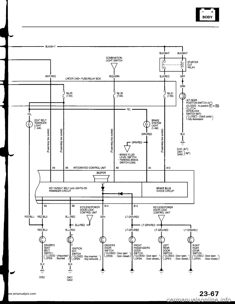
GRY
IGRN
I
rql)
Y4-orotI POSTT1ON SWTTCH (A/T)I (cLosED In posrlion Eor NII . CLUTCNI INTERLOCKI swrTcH (M,T)I /CLOSED :Clulch Dedal\
| \lullydeprsssed I
II8LK
{
Gl01 (A,T)
f;iillrvrr
-"'-},,,,,"
Y l1eff E
v**JT"
g
' BFAKE FLUIDLEVEL SWITCH'PARKING BRAKEswrTcH (usA)
A8A6 INTEGRATED CONTROL UNIT
KEY]N/SEAT BELT and LIGHTS.ONREMINDER CLRCUIT
COMBlNATIONLIGHT SWIlCH
\-7
IREO/GFN
KEYLESS/POWERDOOB LOCKCONTROL UNlT
V
GFN/nED+-]
LTGRN/R€D LT GRN/RED
tl
d[' 4P'\\s.i
EF's l*'n IFF^I'
13fft" l39P*:Door oper ) | fCLOSED. Doo'open ) | fCLO#D. Door ooe. ). Door dos€d,
I
\oPE . 000' closed,
|
\oPE Door ciosed,
ll-- --
,,,[:
ltrh::ffIxl,,'.l'"
l*,*,J IBLU/ BED I
AA
Y Y*,u,.,
I cvro | Bft_oi|l
sl:$P)l lHfi.#' Hrtrff"% ) l
(3!?i".
TI:l
G40tG402
6
DRIVER'SSEATBELTswrTcHrcLosED(OPEN
YEL
RED/BLU
SEAT EELTREM NDERLIGHT(1.4W)
\-
i
I
:
*,
/BLU RED/BLU
q
FEO/BLU
I
dF)
Y*lsE
13fr
l(3BtK
4
www.emanualpro.com
Page 1230 of 1395
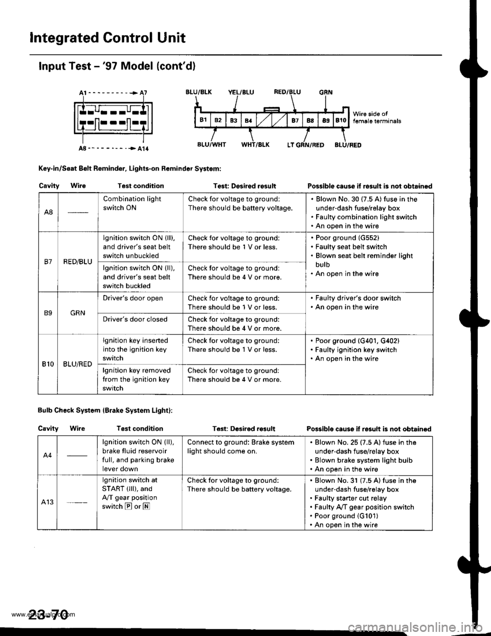
lntegrated Control Unit
Input Test -'97 Model (cont'd)
At----------+A7
Key-in/Seat Belt Reminder, Lights-on Remindor System:
Cavity WireTest conditionTest: Desired rosultPossible cause if re3ult is nol obtainod
Bulb Check System (Brake System Light):
Cavity WireTest conditionT6st: DGsirgd rosultPossible cause if resuh is not obtainod
23-70
A8
Combination light
switch ON
Check for voltage to ground:
There should be battery voltage.
Blown No.30 (7.5 A) fuse in the
under-dash fuse/relay box
Faulty combination light switch
An open in the wire
B7R ED/BLU
lgnition switch ON {lll.
and driver's seat belt
switch unbuckled
Check for voltage to ground:
There should be 1 V or less.
Poor ground (G552)
Faulty seat belt switch
Blown seat belt reminder light
bulb
An open in the wirelgnition switch ON (ll),
and driver's seat belt
switch buckled
Check for voltage to groundl
There should be 4 V or more.
B9GRN
Driver's door openCheck ior voltage to ground:
There should be 1 V or less.
. Faulty driver's door switch. An open in the wire
Driver's door closedCheck for voltage to ground:
There should be 4 V or more.
810BLU/RED
lgnition key insened
into the ignition key
switch
Check for voltage to ground;
There should be 1 V or less.
Poor ground (G401, G,[02)
Faulty ignition key switch
An open in the wire
lgnition key removed
trom the ignition key
swrtch
Check for voltage to ground:
There should be 4 V or more.
A4
lgnition switch ON { ll),
brake fluid reservoir
full, and parking brake
tever oown
Connect to ground: Brake system
light should come on.
Blown No. 25 (7.5 A) iuse in the
under-dash fuse/relay box
Blown brake system light bulb
An open in the wire
A13
lgnition switch at
START (lll), and
A/T gear position
switch E or E
Check for voltage to ground:
There should be battery voltage.
Blown No.31 (7.5 A) fuse in the
under-dash fuse/relay box
Faulty starter cut relay
Faulty A/f gear position switch
Poor ground (G101)
An open in the wire
www.emanualpro.com
Page 1234 of 1395
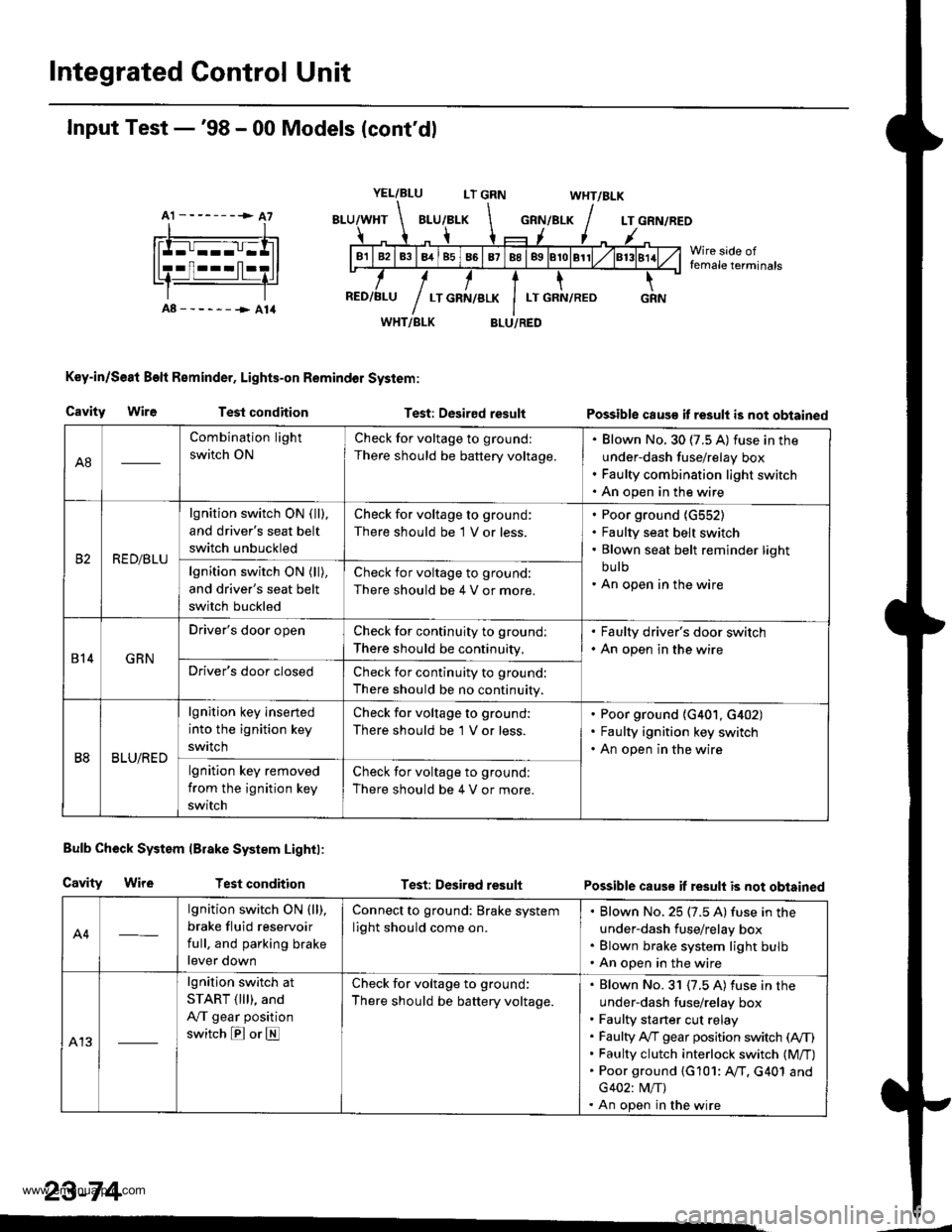
Integrated Control Unit
A1 --------> A7
Input Test -'98 - 00 Models (cont'dl
YEL/BLULT GRNWHT/BLK
GRN/BLKLT GRN/REO
Wire side offemale terminals
A8------->A14WHT/BLK
Key-in/Se8t Beft Reminder, Lights-on Remindol System:
BLU/RED
Cavity WireTest conditionTest: Desired resultPossible caus€ it result is not obtained
Bulb Check System lBrake System Lightl:
Cavity WireTest conditionTest: Desired resultPossible caus€ if result is not obtained
A4
lgnition switch ON (ll),
brake fluid reservoir
full, and parking brake
lever down
Connect to ground: Brake system
light should come on.
Blown No. 25 (7.5 A) fuse in the
under-dash fuse/relay box
Blown brake system light bulb
An open in the wire
A13
lgnition switch at
START ( lll), and
A,/T gear position
switch E or E
Check for voltage to ground:
There should be battery voltage.
Blown No. 31 {7.5 A) fuse in the
under-dash fuse/relay box
Faulty sta rter cut relay
Faulty A,/T gear position switch (A,/T)
Faulty clutch interlock switch (M/T)
Poor ground {G101: AfI. G401 and
G402: M/T)
An open in the wire
23-74
A8
Combination light
switch ON
Check for voltage to ground:
There should be battery voltage.
Blown No. 30 (7.5 A) fuse in the
under-dash fuse/relay box
Faulty combination light switch
An open in the wire
RED/BLU
lgnition switch ON ( ll),
and driver's seat belt
switch unbuckled
Check for voltage to ground:
There should be 1 V or less.
Poor ground {G552)
Faulty seat belt switch
Blown seat belt reminder light
bu lb
An open in the wirelgnition switch ON (ll),
and driver's seat belt
switch buckled
Check for voltage to ground:
There should be 4 V or more.
814GRN
Driver's door openCheck for continuity to ground:
There should be continuity,
. Faulty driver's door switch. An open in the wire
Driver's door closedCheck for continuity to ground:
There should be no continuity.
B8BLU/RED
lgnition key inserted
into the ignition key
swrtch
Check for voltage to ground:
There should be 'l V or less.
Poor ground (G401, G402)
Faulty ignition key switch
An open in the wire
lgnition key removed
from the ignition key
switch
Check for voltage to ground:
There should be 4 V or more.
www.emanualpro.com
Page 1299 of 1395
IJ
Restraints
Seat Belts .....24-1
Supplemental Restraint SYstem
(sRSl ......'.'. ""'.""".""""24-13
Seat Belts
Component Location Index .'."..'..'-'.' 24'2
Front Seat Belt Replacement '......"'.. 24-3
Rear Seat Belt Replacement ......'.". '.' 24-6
f, - lnspection .....""""""""' 24-9
Child Seat Tether Anchor
lnstallation -'97 - 99 Models ."'."24-10
Child Seat Tether Anchor
Removal/lnstallation
-'00 Model ....'......'.'....'.'.."-'-'."' 24'11
l-
www.emanualpro.com
Page 1300 of 1395
Seat Belts
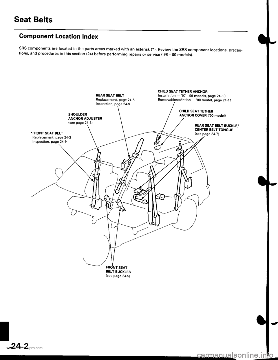
Component Location Index
SRS components are located in the parts areas marked with an asterisk {*). Review the SRS component locauons, precau-tions, and procedures in this section (24) before performing repairs or service (,98 _ 00 models).
CHILD SEAT TETHEN ANCHORlnstallation -'97 99 models, page 24-10Removal/lnstallation - '00 model, page 24-11
CHILD SEAT TETHERANCHOR COVER ('00 mod€tl
REAR SEAT BELT BUCKLE/CENTER BELT TONGUE(see page 24-7).FRONT SEAT BELTReplacement, page 24 3Inspection, page 24-9
BELT EUCKLES(see page 24 5)
24-2
,--.4
www.emanualpro.com
Page 1301 of 1395
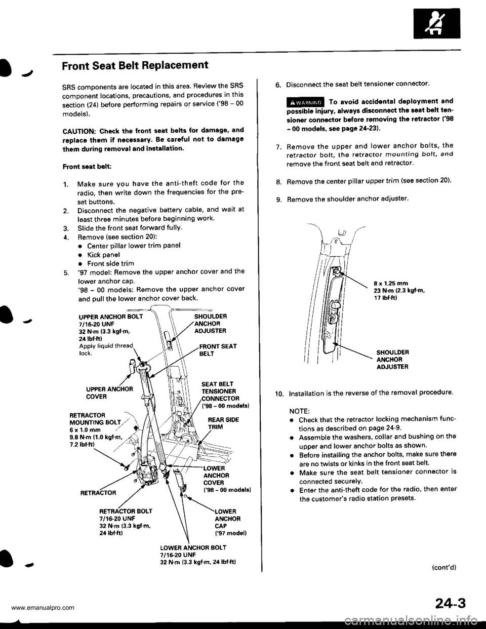
JFront Seat Belt RePlacement
SRS components are located in this area. Review the SRS
component locations, precautions, and procedures in this
section (24) before performing repairs or service ('98 - 00
models).
CAUTION: Check the front seat bslts for damago. and
replaco thom if necessary. Be careful not to damage
them during removal and in3tallation'
Front scat bolt:
1. Make sure you have the anti-theft code for the
radio, then write down the frequencies for the pre-
set buttons.
2. Disconnect the negative battery cable, and wait at
least three minutes before beginning work.
3. Slide the front seat forward fully.
4. Bemove (see section 20):
. Center pillar lower trim Pane
. Kick oanel
. Front side trim
5. '97 model: Remove the upper anchor cover and the
lower anchor caP.'98 - oO models: Remove the upper anchor cover
and pull the lower anchor cover back.
UPPEN ANCHOR BOLT
7/1&20 UNF32 N.m (3.3 kgt'm.24 tbf.ft)
SHOULDERANCHORADJUSTER
Apply liquid threadlock.
9.8 N.m (1.0 kgt.m,?.2 tbtft)
UPPERCOVER
RETRACTORMOUNTING BOLTZ,,Gx1.0mm ./
SEAT BELTTENSIONER
{'98 - 0o modols)
REAR SIDE
ANCHORCOVERl'98 - 00 models)
ANCHORCAP('97 modell
RETRACTOR BOLT7/1&20 UNF32 N.m 13.3 kgt m,24 tbt.ft)
LOWER ANCHOR BOLT?,/1&20 UNF32 N.m {3.3 kgf.m, 2,1 lbf.ftl
o.Disconnect the seat belt tensiongr connector.
@ To avoid accidontal deployment and
possibte inlury, always disconnect the soat bsh ton-
sion€r connoctor bofore rsmoving th6 retractor l'98
- 00 modsls, se€ pa ge 21-231 .
Remove the uDDer and lower anchor boits, the
retractor bolt, the retractor mounting bolt, and
remove the front seat belt and retractor.
Remove the center pillar upper trim (see section 20).
Remove the shoulder anchor adjuster.
7.
9.
8.
I x 1.25 mm23 N.m 12.3 kgt.m,1? tbf.ft)
SHOULDERANCHORADJUSTER
10. lnstallation isthe reverse of the removal procedure.
NOTE:
Check that the retractor locking mechanism func-
tions as described on Page 24-9.
Assemble the washers, collar and bushing on the
uooer and lower anchor bolts as shown.
Eefore installing the anchor bolts, make sure there
are no twists or kinks in the front seat belt.
Make sure the seat belt tensioner connector ls
connected securelv.
Enter the anti-theft code for the radio, then enter
the customer's radio station presets
(cont'd)
24-3
www.emanualpro.com
Page 1302 of 1395
Seat Belts
Front Seat Belt Replacement {cont'dl
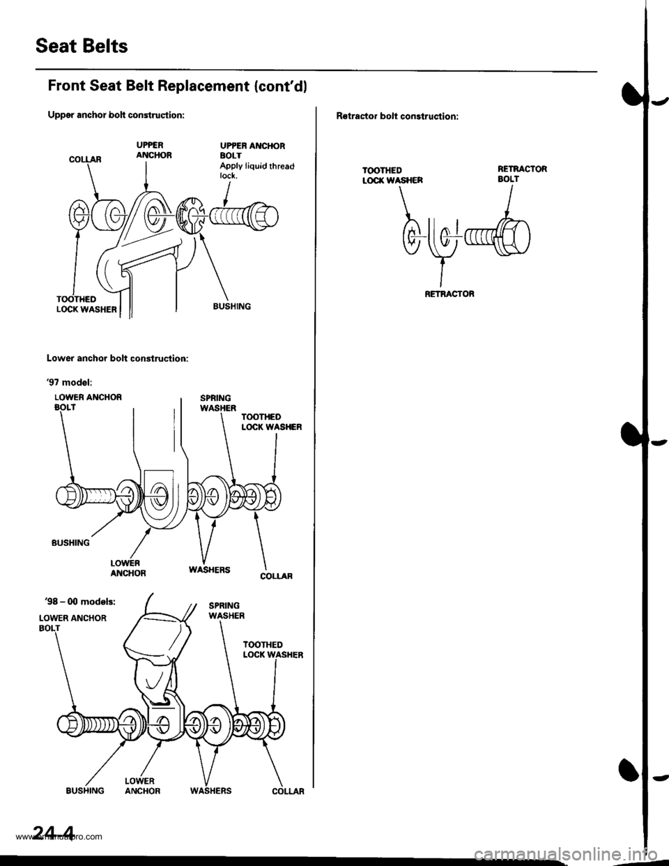
Uppgr anchor boh construqtion:
UPPEB AI{CHORaolTApply liquid threadtock.
Lower anchor bolt construction:
'97 modol:
LOWER ANCHOR
24-4
,--
R€tractor bolt construqtion:
T(X)THEDLOCI( WASHCR
RETNACTORBOLT
bwd
RETBACTOR
www.emanualpro.com
Page 1303 of 1395
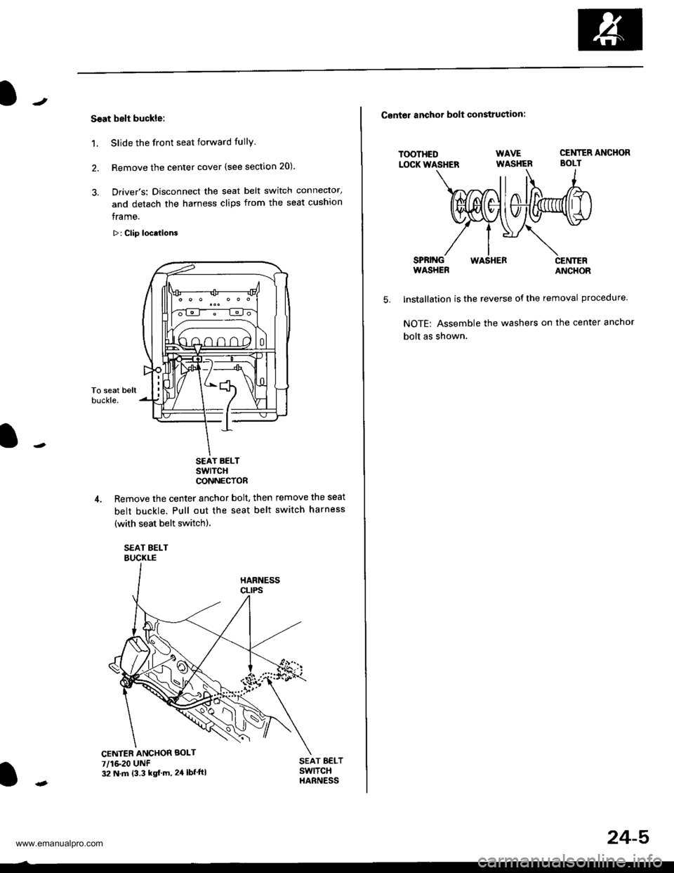
Ssat belt buckle:
1. Slide the front seat forward fully
2. Remove the center cover (see section 20).
3. Driver's: Disconnect the seat belt switch connector,
and detach the harness clips from the seat cushion
frame.
>: Clip locations
To seat beltbuckle.
SEAT BELTswlTcHCONNECTOR
4. Remove the center anchor bolt, then remove the seat
belt buckle. Pull out the seat belt switch harness
(with seat belt switchl.
SEAT BELTBUCKLE
SEAT B€LTSwlTCHHARNESS
CENTER ANCHOR BOLT
7/1&20 UNF32 N.m {3.3 kg{ m, 24 lbf ftl
24-5
Csntor anchor bolt construstion:
TOOTHEDLOCK WASHER
SPRINGWASHERWASHERCENTERANCHOR
WAVE CENTER ANCHOR
WASHER BOLT
5.lnstallation is the reverse of the removal procedure.
NOTE: Assemble the washers on the center anchor
bolt as shown.
www.emanualpro.com
Page 1304 of 1395
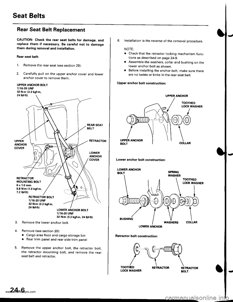
Seat Belts
Rear Seat Belt Replacement
CAUTION: Check the rear s€at belts for damage, andreplace lhem if necessa.y. Be caretul not to damagethem during temoval and installation.
Rear seat belt:
1, Remove the rear seat {see section 20}.
2. Carefully pull on the upper anchor cover and loweranchor cover to remove them.
UPPER ANCHOR BOLT7/16-20 UNF32 N.m 13.3 kg{.m,24 tbt.ft)
REAR SEATBELT
RETRACTOBMOUNTING BOLT6x1.0mm9.8 N.m (1.0 kgt.m.7.2 rbf.ftl
UPPERANCHORCOVER
RETRACTOR
LOWERANCHORCOVER
RETRACIOR EOLT7/16-20 UNF32 N.m {3,3 kgf.m,24 rbr.ft)
3.
4.
LOWER ANCHOF BOLT7/1S20 UNF32 N.m 13.3 kgl.m, 2/r lbf.ftl
Remove the lower anchor bolt.
Remove (see section 20):. Cargo area floor and cargo storage bin. Rear trim panel and rear side trim panel
Remove the upper anchor bolt, the retractor bolt.the retractor mounting bolt, and remove the rearseat belt and retractor.
24-6
,--
6. Installation is the reverse of the removal procedure.
NOTE:
. Check that the retractor locking mechanism func-tions as described on page 24-9.. Assemble the washers, collar and bushing on thelower anchor bolt as shown.. Before installing the anchor bolt, make sure thereare no twists or kinks in the rear seat belt.
Upper anchot bolt construction:
UPPER ANCHOR
TOOTHEOLOCK WASHER
/
A t
ANCHORCOLLAF
Lowel anchor bolt construqtion:
LOWER ANCHORBOLTSPRINGWASHEB
TOOTHEDLOCI( WASHER
BUSHINGWASHERSCOLLAR
LOWER ANCHOR
Rgtractor boll construction:
RETMCTORBOLT
/ r>--->.
f/F\-. (t--nnnllH \
P \v*\
/\\T(X)THEDLOCK WASHERRETRACTOR
www.emanualpro.com