Seat belt HONDA CR-V 1998 RD1-RD3 / 1.G User Guide
[x] Cancel search | Manufacturer: HONDA, Model Year: 1998, Model line: CR-V, Model: HONDA CR-V 1998 RD1-RD3 / 1.GPages: 1395, PDF Size: 35.62 MB
Page 1038 of 1395
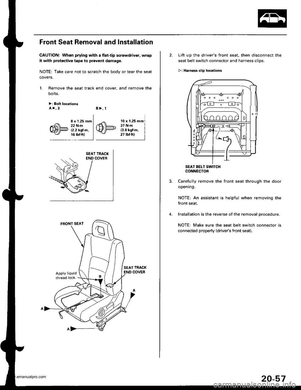
Front Seat Removal and Installation
CAUTION: When prying whh a tlat-tip screwdrivor, wrap
it with proteqtive tape to prevent damage.
NOTE: Take care not to scratch the bodv or tear the seat
covers.
1. Remove the seat track end cover, and remove the
bolts.
>: Bolt loc.tionsA>.3B>, 1
I x 1.25 mm22 N.mi'2.2 kgl.m,16 rbf.ftl
10 x 1.25 mm37 N.m13.8 kgt.m,27 tbt.ftl
2. Lift up the driver's front seat, then disconnect the
seat belt switch connector and harness clips.
>: Hrrnoss clip loc.lions
SEAT BELT SW]TCHCONNECTOR
Carefully remove the front seat through the door
opening.
NOTE: An assistant is helpful when removing the
front seat.
Installation is the reverse of the removal procedure.
NOTE: Make sure the seat belt switch connector is
connected properly (driver's front seat).
20-57
www.emanualpro.com
Page 1045 of 1395
Seats
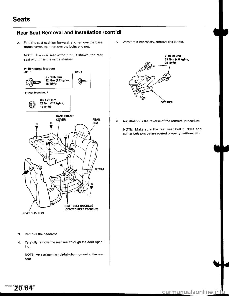
Rear Seat Removal and Installation
2. Fold the seat cushion forward, and remove the base
frame cover, then remove the bolts and nut.
NOTE: The rear seat without tilt is shown, the rear
seat with tilt is the same manner.
>i Boh screw locetionsA>, 1
8 x 1.25 mm22 N.m {2.2 kgf.rn,16 rbtft)
B>, 4
@t
a: Nut loc.iion, 'l
8 x 1.25 mm22 N
Carefully remove the rear seat through the door open-
ing.
NOTE: An assistant is helptul when removing the rear
seaI.
20-64
?
4.
BASE FRAME
SEAT BELT BUCKTES(CENTER BELT TONGUEI
SEAT CUSHION
(cont'dl
5. With tilt: lf necessary, remove the striker.
lnstallation is the reverse of the removal procedure.
NOTE: Make sure the rear seat belt buckles and
center belt tongue are routed properly (without tilt).
.-
www.emanualpro.com
Page 1049 of 1395
Seats
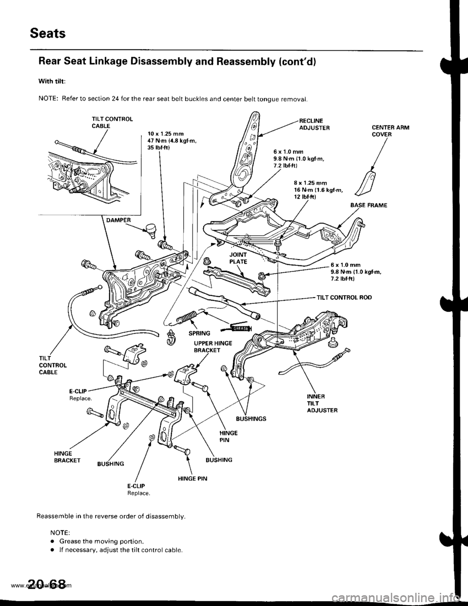
Rear Seat Linkage Disassembly and Reassembly (cont'd)
with tilt:
NOTE: Refer to section 24 for the rear seat belt buckles and center belt tongue removal
TILT CONTFOLCABLE10 x 1.25 mm47 N.m {i1.8 kgt.m,35 tbf.ft)
ARM
6x1.0mm9.8 N.m n.0 kgt.m,7.2 tbt.tll
CENTEBCOVER
/
n
//-)
ASE FRAME
8 r 1.25 mm16 N.m (1.6 kgf.m,12 tbt.ftl
DAMPER
6x1.0mm9.8 N.m 11.0 kgtm,7.2 tbttr)
TILT CONTROL ROD
A
@
SPRING
UPPER HINGE
TILTCONTROLCABLE
Replace.
q
BUSHING
E.CLIPReptace.
Reassemble in the reverse order of disassembly.
NOTE:
. Grease the moving ponion.
. lf necessary, adjust the tilt control cable.
20-64
HINGE PIN
www.emanualpro.com
Page 1090 of 1395
a
Heater and Air Conditioning
Heater ...........21
NOTE: Section 21 ("Heater") is included in section 22.
Air Conditioning ......'..'.. '.'22'1
SUPPLEMENTAL RESTRAINT SYSTEM (SRS}
This model has an SRS which includes a driver's airbag in the steering wheel hub, a passenger's airbag in the dashboard
above the glove box ('97,00 models). and seat belt tensioners in the seat belt retractors ('98 - 00 models). Information
necessary to safely service the SRS is included in this Service Manual. ltems marked with an asterisk (*) on the contents
page include. or are located near, SRS components. Servicing, disassembling or replacing these items will require special
precautions and tools, and should only be done by an authorized Honda dealer.
@. To avoid rendering the SRS inoperative, which could lead to personal iniury or death in the event of 8 severe frontal
collision, all SRS service work must be performed by an authotized Honda dealer.
lmproper service procedures, including incorrect removal and installation of the SRS, could lead to personal iniury
caused by unintentional deployment of the airbags ('97 - 00 models), and seat belt tensioners 138 - 00 models).
Do not bump the SRS unit. Otherwise, the system may fail in case of a collision, or the airbags may deploy when the
ignition switch is ON {lll.
SRS eleqtrical wiring harnesses are identified by yellow color coding. Related components are located in the steering
column, front console, dashboard, dashboard lower panel, and in the dashboard above the glove box. Do not use elec-
tricaltest equipment on thes€ cilcuils.
www.emanualpro.com
Page 1186 of 1395

Connector ldentification and Wire Harness Routing
Left Side Wire Harness
Connector oI
Terminal
Number of
CavitiesLocaiionConnects toNot6s
c551
c552
c554
c556
c558
c559
c559
c560
c562
c563
c563
c564
c565
c566
c568
c569
c570
c572
c573
c57 4
c575
c576
c578
c579
c580
c581
8
16
10
14'I
14
16
20
20
24
)
1
5
1
1
6
1
2
14
1
1
6
1
6
Behind under-dash fuse/relay box
Behind under-dash fuse/relay box
Left side of steering wheel
Left side of steering wheel
Left side of steering wheel
Above under-dash fuse/relay box
Above under-dash fuse/relay box
Driver's door
Behind left kick panel
Behind left kick panel
Behind left kick panel
Left side offloor
Left quaner panel
Fueltank
On left half of rear cross beam
On left half of rear cross beam
Left quarter panel
Left quarter panel
Left quarter panel
Left quarter panel
Left quarter panel
Left quarter panel
On left half of rear cross beam
Right quarter panel
Right quarter panel
Left quarter pillar
Left side of floor
Left B-piller
Left B-piller
Behind left kick panel
Behind left kick panel
Under left side of dash
Left B-piller
Fueltank
Left side of steering wheel
Under-dash fuse/relay box (C921)
Under-dash fuse/relay box (C923)
Power mirror switch
Power window master switch
Power window master switch
Dashboard wire harness {C505)
Dashboard wire harness 1C505)
Driver's door wire harness (C661)
Main wire harness (C403)
Main wire harness (C404)
Main wire harness (C404)
Driver's seat belt switch
Left rear door switch
Fuel unit
Left rear ABS wheel sensor
Left rear ABS wheel sensor
Rear accessory socket connector {+}
Rear accessory socket connector (-)
Rear bumper wire harness 1C641)
Trailer lighting connector
Tailgate door latch switch
Left rear speaker
Right rear ABS wheel sensor
Rear wire harness (C611)
Right rea. door switch
Left taillight
Parking brake switch
Left rear door wire harness (C681)
Driver's door switch
Select unlock relay (for security alarm
system)
Junction connector (for power door
locks)
SRS main harness (C807)
Driver's seat belt tensioner
Fuel tank pressure sensor sub-harness(c645)
Power window master switch
'97 - 98
mooets'99 - 00
models
'97 model'98 - 00
models
Optional
'97 model'98 - 00
models
'98 - 00
mooets'98 - 00
models'98 - 00
mooets'99 - 00
mooets
G551
G553
Behind left kick panel
Left side ot floor
Left quarter piller
Body ground, via left side wire harness
Body ground, via left side wire harness
Body ground, via left side wire harness
23-26
www.emanualpro.com
Page 1188 of 1395
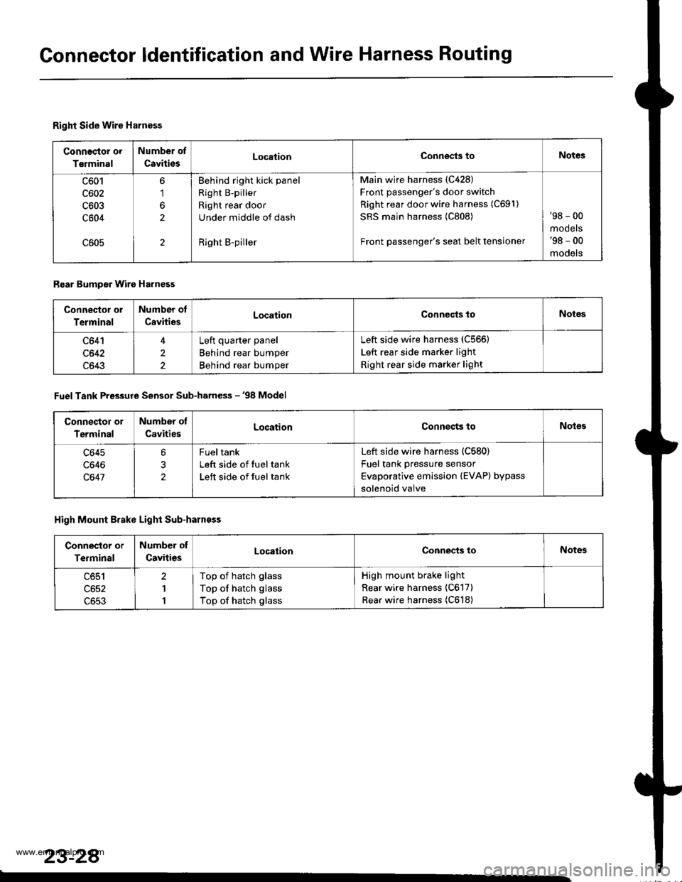
Gonnector ldentification and Wire Harness Routing
Right Side Wire Harness
Connec{or or
Tsrminal
Number of
CavitiesLocationConnests toNotes
c601
c602
c603
c604
6'1
2
2
Behind right kick panel
Right B-piller
Right rear door
Under middle of dash
Right B-piller
Main wire harness (C428)
Front passenger's door switch
Right rear door wire harness (C691)
SRS main harness {C808)
Front passenger's seat belt tensioner
'98 - 00
mooets'98 - 00
models
Rear Bumper Wire Harness
Connector ol
Terminal
Number ot
CavitiesLocationConnocts toNotes
c641
c642
c643
4
2
2
Left quarter panel
Behind rear bumper
Behind rear bumper
Left side wire harness (C566)
Left rear side marker light
Right rear side marker light
Fuel Tank Pressure Sensor Sub-harness - '98 Model
Connector or
Terminal
Number ot
CavitiesLocationConnects toNot63
c645
c646
c647
?
2
Fueltank
Left side of fuel tank
Left side of fuel tank
Left side wire harness (C580)
Fuel tank pressure sensor
Evaporative emission (EVAP) bypass
solenoid valve
High Mount Brake Light Sub-harnoss
Conneslor or
Terminal
Number of
CavitiesLocationConnec-ts toNotes
c651
c652
c653
2
1
1
Top of hatch glass
Top of hatch glass
Top of hatch glass
High mount brake light
Rear wire harness (C617)
Rear wire harness (C618)
23-28
www.emanualpro.com
Page 1208 of 1395
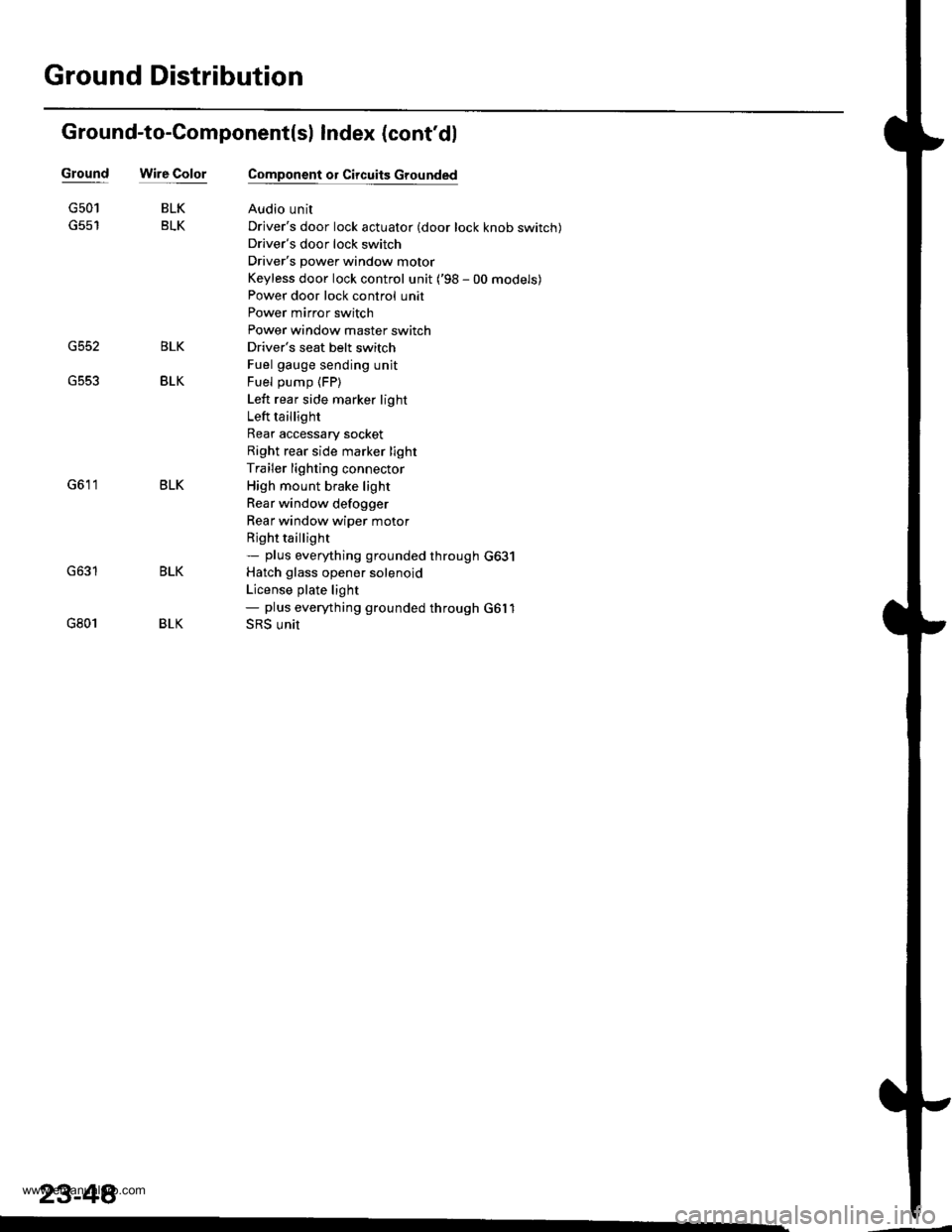
Ground Distribution
Ground-to-Component(sl Index (cont'dl
Wire ColorGround
G552
G501
G801
BLK
BLK
BLK
BLK
Component or Circuits Grounded
Audio unit
Driver's door lock actuator (door lock knob switch)
Driver's door lock switch
Driver's power window motor
Keyless door lock control unit ('98 - 00 models)
Power door lock control unit
Power mirror switch
Power window master switch
Driver's seat belt switch
Fuel gauge sending unit
Fuel pump (FP)
Left rear side marker light
Left taillight
Rear accessary socket
Right rear side marker light
Trailer lighting connector
High mount brake light
Rear window defogger
Rear window wiper motor
Rjght taillight- plus eveMhing grounded through G631
Hatch glass opener solenoid
License plate light- plus eveMhing grounded through G6l1
SRS unit
BLK
BLK
BLK
23-48�
www.emanualpro.com
Page 1217 of 1395
l-
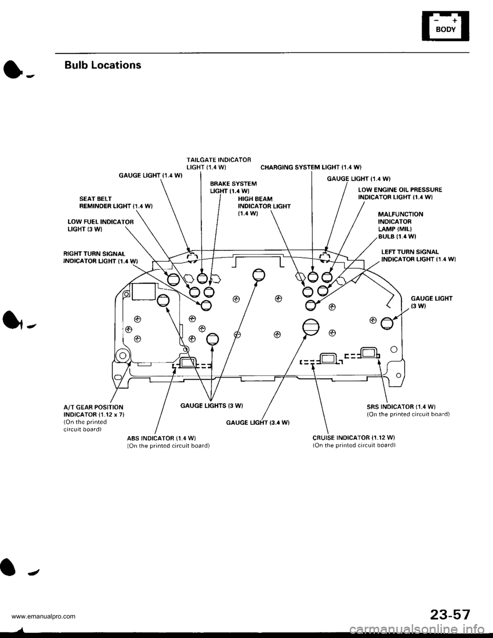
Bulb Locations
TAILGATE INDICATORLIGHT (,I.4 W) CHARGING SYSTEM LIGHT (1.4 WI
GAUGE LIGHT {1.4 WIGAUGE LIGHT I1,4 WIBRAKE SYSTEMLTGHT 11.4 WlLOW ENGINE OIL PRESSUREINDICATOR LIGHT {1./r W}SEAT BELTREMINDER LIGHT {1.' W'HIGH BEAMINDICATOR LIGHT
LOW FUEL INOICATOBLIGHT 13 WI
MALFUNCTIONINOICATORLAMP {MIL)BULB I1.4 WI
{1.4 Wl
RIGHT TURN SIGNALINDICATOR LIGHT I1.' WI
GAUGE LIGHTS 13 WI
LEFT TURN SIGNALINDICATOR LIGHT {1,4 W}
GAUGE LIGHT
t3 wl
SRS INDICATOR ('1./t W)(On the printed circuit board)
1,.
A/T GEAR POSITIONINDICATOR {1.12 x 7}(On the printed
circuit board)GAUGE LIGHT {3.' W}
ABS INDICATOR (1,4 W)
lOn the printed circuit board)cRutsE tNDtcAToR 11.r2 w)(On the printed circuit board)
f-= F -
J
23-57
www.emanualpro.com
Page 1220 of 1395
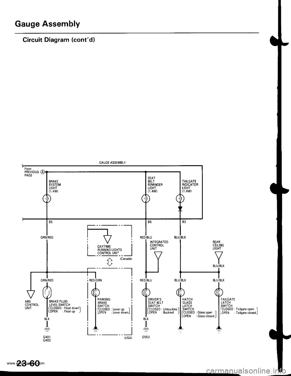
Gauge Assembly
Circuit Diagram (cont'd)
GAUGE ASSEMBLY
REARCEILINGLIGHT
TAILGATELATCHswtTcH
rCLOSED I Glass open ItoPEN : Glass closed I
fCLoSED rTailsate open II0PEN iTailsateclosed.J
23-60
BLK
T
G552tlsA)-
AI Jl
I SRAKE FLUIOI LEVET SWITCHI fCLOSED . Floal down)
lLoPEN . Floal up J
BLK
+
G401G402
ABSCONTROLUNIT
PREVIOUSPAGE
a1
\J
BRAKESYSTEMLIGHTl1.4Wl
\
./
SEATBELTREMINDERLIGHT(1.4W)
\/'
7\
\
TAILGATEINDICATORLIGHT{1.4W}
Gnru;neo I f7 |
I i oo,,#, i| | RUI\N|NG 0GHTS I
I L__c_o!l!g_yI'__l
I t
rcanada)
l\
-l I
BED
RED
B6
'BLU
I INTEGRATEDI coNTRoLI UN|T
lv
IItt
r-IBLU
www.emanualpro.com
Page 1224 of 1395
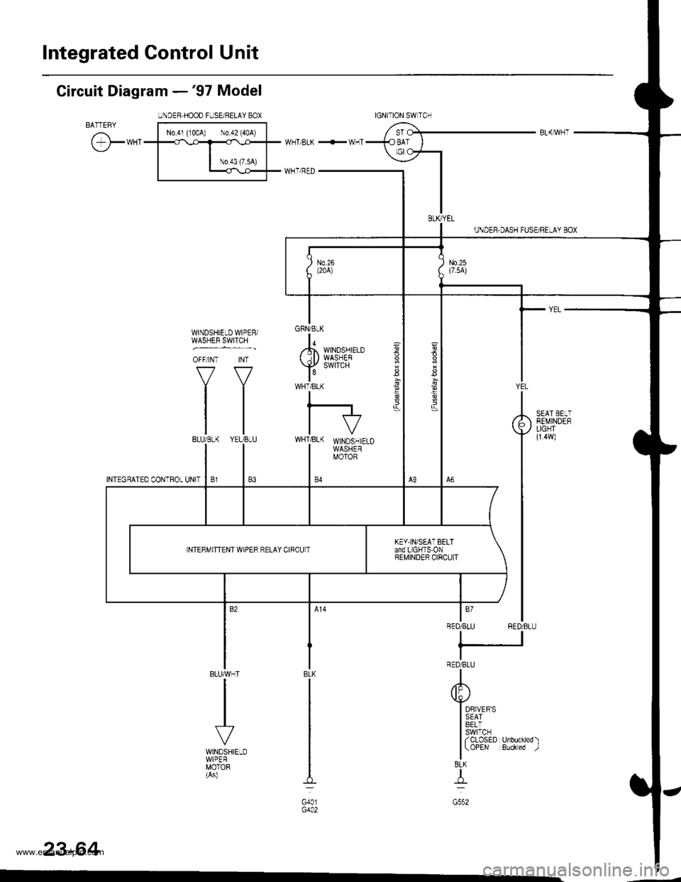
Integrated Gontrol Unit
Circuit Diagram -'97 Model
UNDER.HOOD FUSEi RELAY 8OXBATTEFYI No.4' {'004) \0.d2'40A) |
cr*"
l__*l;;T
w_T ELK +!v_T
I H-uTr.r--i=r-
GFNi BLK
lo,,.h WINDSHIELD( il) WASHEB
Y
SWITCH
WHTiBLK
I
l-IVWHT]BLK WINDSHIELDI WASHERI MOTOB
WINDSHIELD WIPER/WASHEF 9WTTCH ,
OFF/INT INT
VV
tltltl
tl
BLUMHT
VWINDSHIELDWIPERMOTOR(As)
ag
3
YEL
RED/BLU
DRIVER'SSEATBELTswtTcHf CLOSED r Unbuckled )(OPEN :Buckled -.1
BEMINDEBLIGHT(r 4w)
BLK
G401
BL(I-tr-l
G552
23-64
tGNITtON SW lCrl
BLKryEL
KEY.IN/SEAT BELTand LIGHTS-ONBEMINDER CIRCUITNTERMITTENT WIPER RELAY CIRCUlT
www.emanualpro.com