engine mount HONDA CR-V 1998 RD1-RD3 / 1.G Owner's Manual
[x] Cancel search | Manufacturer: HONDA, Model Year: 1998, Model line: CR-V, Model: HONDA CR-V 1998 RD1-RD3 / 1.GPages: 1395, PDF Size: 35.62 MB
Page 436 of 1395
Flywheel
Inspection
2.
3.
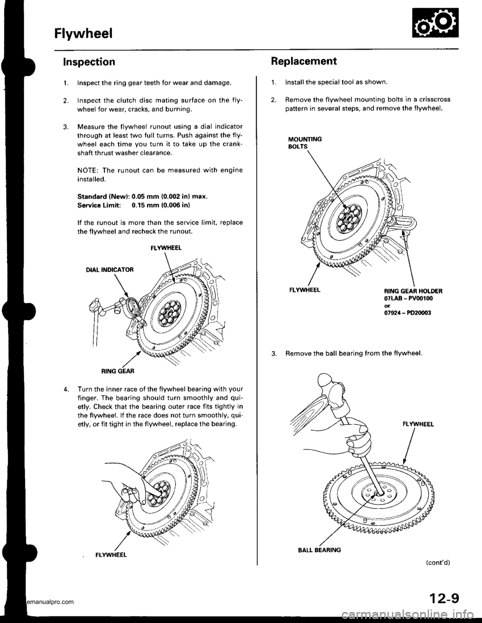
Llnspect the ring gear teeth for wear and damage.
Inspect the clutch disc mating surface on the fly-
wheel for wear, cracks, and burning
Measure the flywheel runout using a dial indicator
through at least two full turns. Push against the fly-
wheel each time you turn it to take up the crank-
shaft thrust washer clearance.
NOTE: The runout can be measured with engine
installed.
Standard (Newl: 0.05 mm (0.002 in) max.
Service Limit: 0.15 mm {0.006 inl
lf the runout is more than the service limit, replace
the flywheel and recheck the runout
Turn the inner race ot the flywheel bearing with your
finger. The bearing should turn smoothly and qui-
etly. Check that the bearing outer race fits tightly in
the tlywheel. lf the race does not turn smoothly, qui-
etly, or fit tight in the flywheel, replace the bearing.
FLYWHEEL
RING GEAR
FLYWHEEL
L
2.
Replacement
Installthe special tool as shown.
Remove the flywheel mounting bolts in a crisscross
pattern in several steps, and remove the flywheel.
MOUNNNGBOLTS
FLYWHEEL
(cont'd)
12-9
RING GEAR HOLDER07LAB - PV00r00ol07924 - PD20003
3. Remove the ball bearing from the flywheel.
BALL BEARING
www.emanualpro.com
Page 449 of 1395
Transmission Assembly
Removal (cont'd)
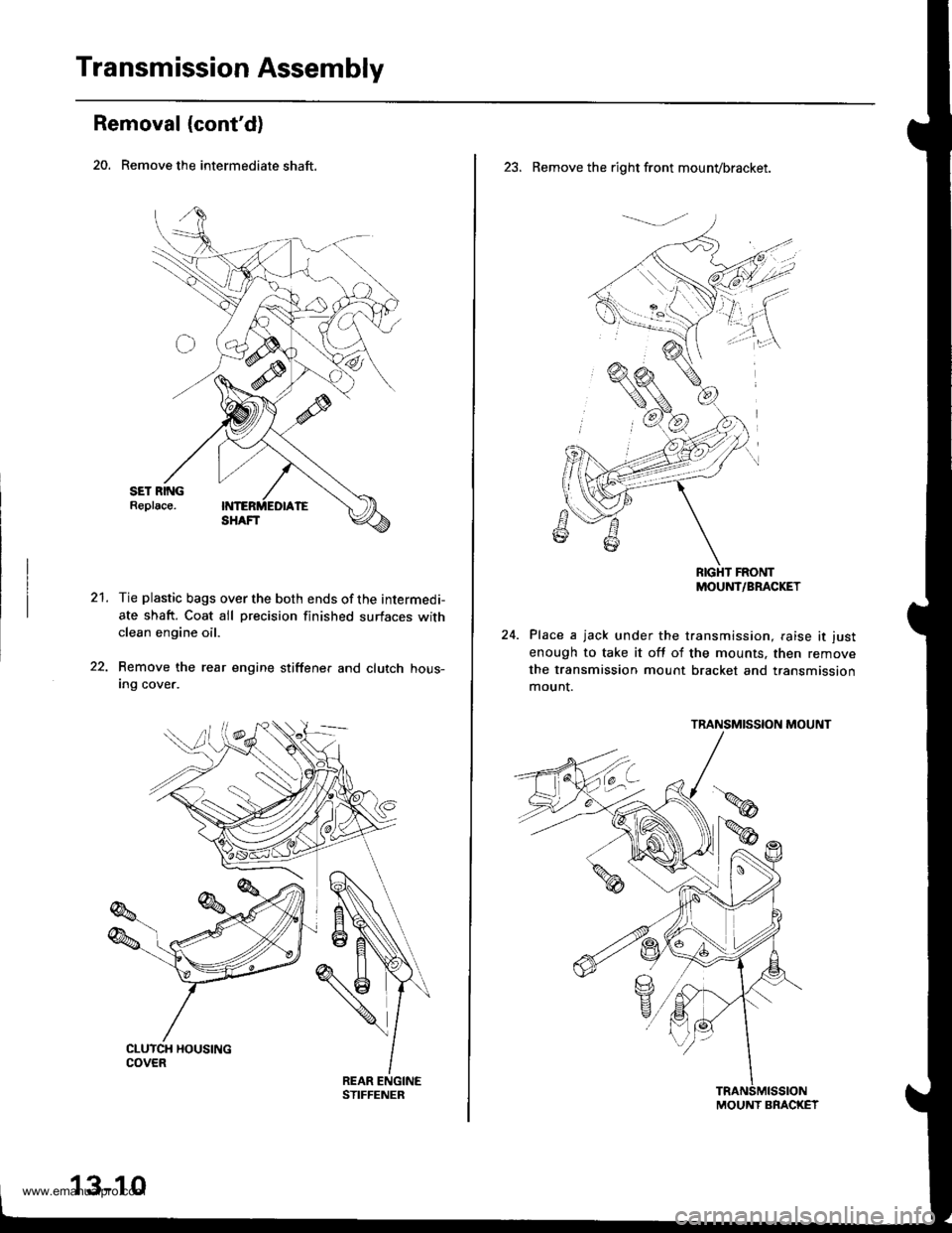
20. Remove the intermediate shaft.
21.Tie plastic bags over the both ends of the intermedi-
ate shaft. Coat all precision finished surfaces withclean engine oil.
Remove the rear engine stiffene. and clutch hous-Ing cover.
13-10
23. Remove the right front mounvbracket.
RIGHT FRONTMOUNT/BRACKET
Place a jack under the transmission, raise it just
enough to take it off of the mounts, then remove
the transmission mount bracket and transmission
mount.
TRANSMISSION MOUNT
MOUNT BRACKET
www.emanualpro.com
Page 450 of 1395
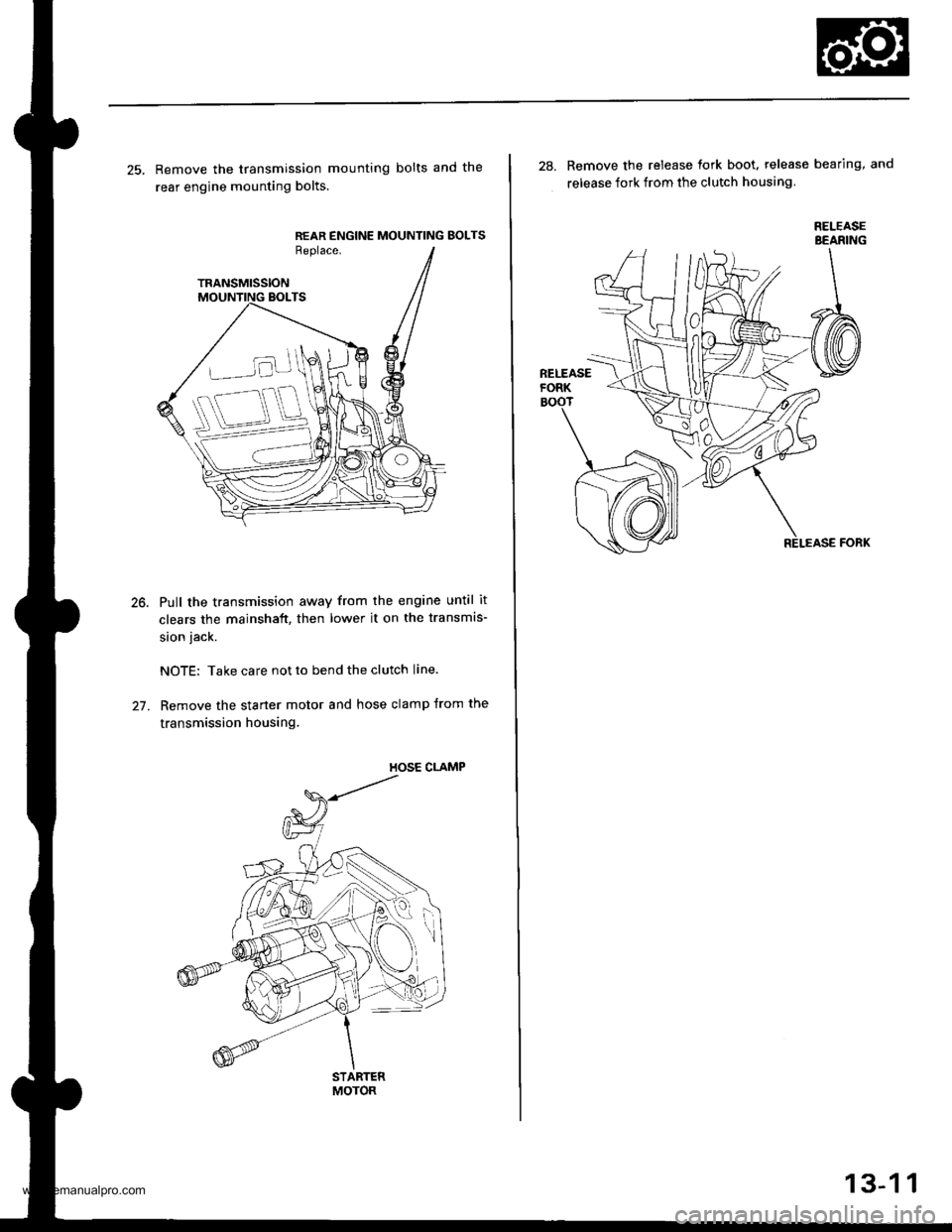
25. Remove the transmission mounting bolts and the
rear engine mounting bolts.
REAR ENGINE MOUNTING BOLTSReplace.
TRANSMISSION
Pull the transmission away from the engine until it
clears the mainshaft, then lower it on the transmis-
sion jack.
NOTE: Take care not to bend the clutch line.
Remove the starter motor and hose clamp from the
transmission housing.
STARTERMOTOR
28. Remove the release tork boot. release bearing, and
release fork from the clutch housing
RELEASEBEANING
13-1 1
www.emanualpro.com
Page 511 of 1395
Transmission Assembly
1.
Installation
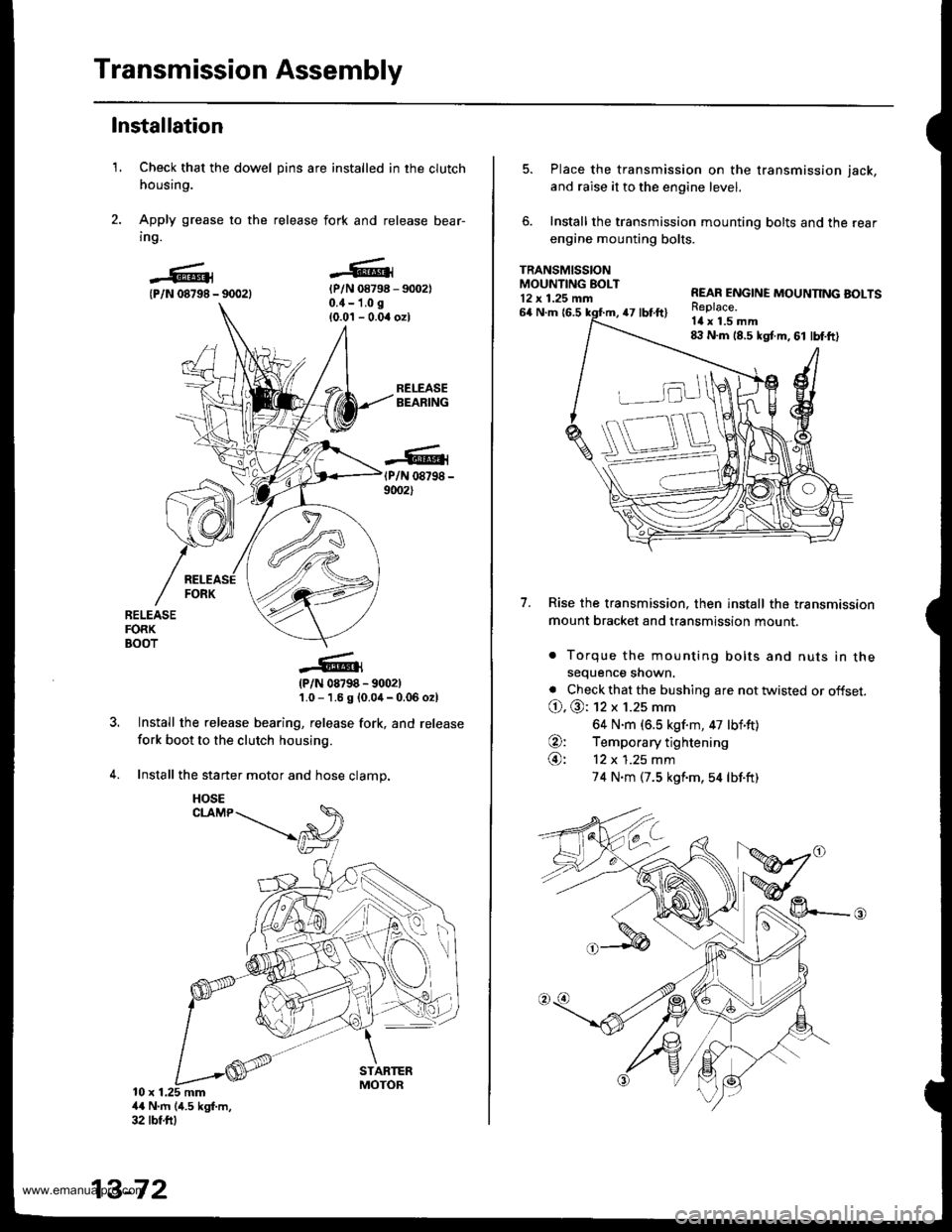
Check that the dowel pins are installed in the clutch
housing.
Apply grease to the release fork and release bear-
ing.
{P/N 08798 - 90021{P/N 08798 - 9002)0.{ - 1.0 g
{0.0'l - 0.04 ozl
RELEASEBEARING
(P/N 08798 -
9002)
RELEASEFORKBOOT
?
(P/N 08798 - 9002)'1.0 - 1.6 g {0.0,1- 0.06 o2l
Install the release bearing, release fork, and release
fork boot to the clutch housing.
Install the starter motor and hose clamp.
10 x 1.25 mm4{ N'm (4.5 kgf.m,32 tbf.ftl
13-72
HOSE
5. Place the transmission on the transmission jack,
and raise it to the engine level.
6. Install the transmission mounting bolts and the rear
engine mounting bolts.
TRANSMISSIONMOUNTING EOLT12 x 1.25 mn
7.
64 N.m {6.547 tbt.ft)
REAR ENGINE MOUNNNG BOLTSReplace.Itl x 1.5 mm8:l N.m 18.5 kgt m, 61 lbf.ft)
Rise the transmission, then install the transmission
mount bracket and transmission mount.
. Torque the mounting bolts and nuts in thesequence shown.
. Check that the bushing are not twisted or offset.
O. @: 12 x 1.25 mm
64 N.m (6.5 kgf.m, 47 lbf'ft)
O: Temporary tightening
@: 12 x 1.25 mm
74 N.m (7.5 kgf'm,54 lbf.ft)
www.emanualpro.com
Page 512 of 1395
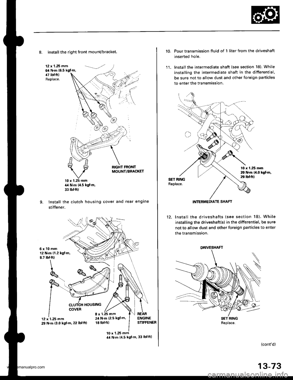
8. Installthe right front mounvbracket.
12 x 1 .25 mm64 N.m (6.5 kgf'm,47 tbf.ftlReplace.
RIGHT FRONTMOUNT/BBACKET
10 x 1.25 mm4,a N.m (4.5 kgf m,
33 tbf ftl
Install the clutch housing cover and rear engine
stiffener.
6xl0mm12 N.m 11.2 kgt.m.8.7 tbf.ft)
HOUSING
'12 x 1.25 mm29 N.m 13.0 kgf.m. 22 lbf'ft)
8 x 1.25 mm24 N.m {2.5 kgf'm'
18 tbl.ft)
10 x 'l .25 mm44 N.m {4.5 kgf m,33 lbf ftl
10. Pour transmission fluid of 1 liter from the driveshaft
inserted hole.
1 1. lnstall the intermediate shaft {see section 18). While
installing the intermediate shaft in the differential.
be sure not to allow dust and other foreign particles
to enter the transmission.
10 r 1.25 mm39 ttm 14.0 kgf.m,29 tbt ftlSET RINGReplace.
12. lnstall the driveshafts (see section 18). While
installing the driveshaft(s) in the differential, be sure
not to allow dust and other foreign panicles to enter
the transmission.
SET RINGReplace.
(cont'd)
13-73
INTERMEOIATE SHAFT
DRIVESHAFT
www.emanualpro.com
Page 520 of 1395
Description
General Operation (cont'dl
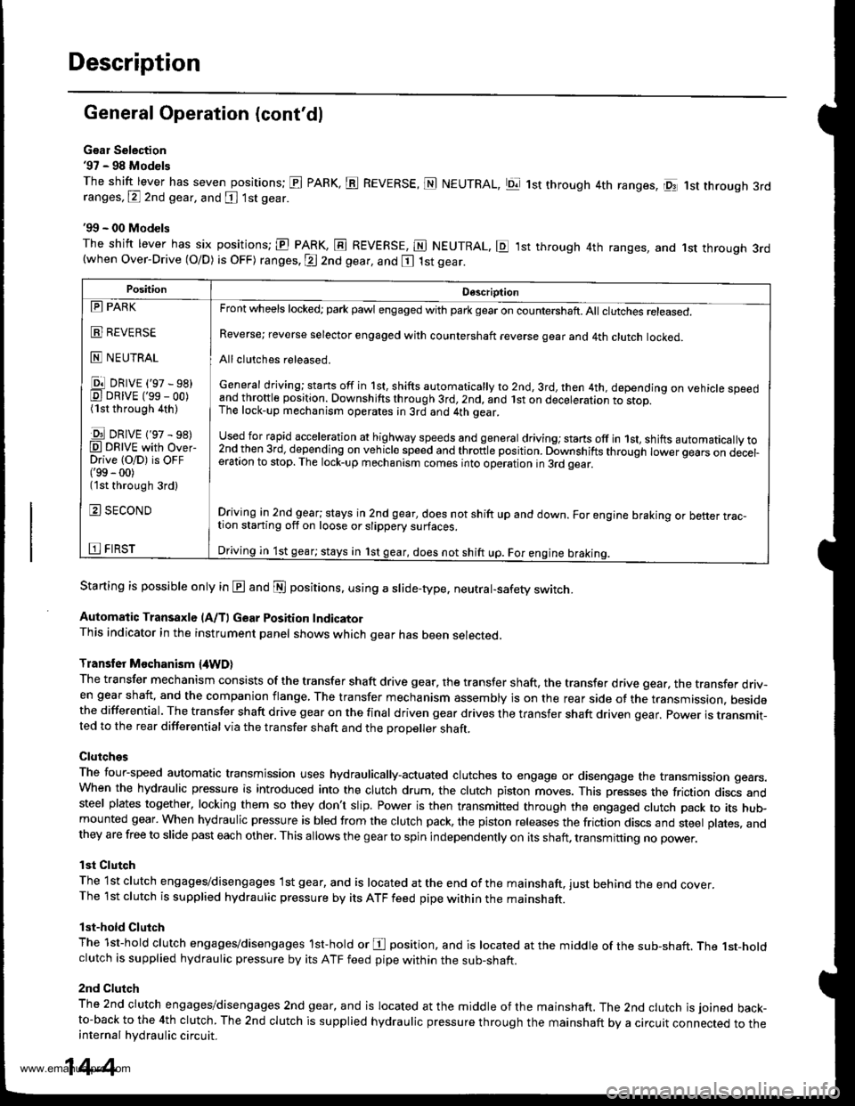
Gsar Selection'97 - 98 Models
The shift lever has seven positions; El PARK, ts REVERSE, N NEUTRAL, Ell 1st through 4th ranges, lpq 1st th.ough 3rdranges, P 2nd gear, and [ 1st gear
'99 - 00 Models
The shitt lever has six positions; El PARK, E REVERSE, E NEUTRAL. E ,lst through 4th ranges, and 1st through 3rd(when Over-Drive (O/D) is OFF) ranges. @ 2nd gear, and E 1st gear.
Starting is possible only in @ and @ positions. using a slide-type. neutral-safety switch.
Automatic Transaxle (A/T) Gear Position IndicatorThis indicator in the instrument panel shows which gear has been selected.
Transler Mochanism {4WD}
The transfer mechanism consists of the transfer shaft drive gear. the transfer shaft. the transfer drive gear, the transfer driv-en gear shaft, and the companion flange, The transfer mechanism assembly is on the rear side ot the transmission. besidethe differential. The transfer shaft drive gear on the final driven gear drives the transfer shaft driven qear. power is transmit-ted to the rear differential via the transfer shaft and the Drooeller shaft.
Clutches
The four-speed automatic transmission uses hydraulically-actuated clutches to engage or disengage the transmission gears.When the hydraulic pressure is introduced into the clutch drum, the clutch piston moves. This presses the friction discs andsteel plates together, locking them so they don't slip. Power is then transmifted through the engaged clutch pack to its hu$mounted gear. When hydraulic pressure is bled from the clutch pack, the piston releases the friction discs and steel plates, andthey are free to slide past each other. This allows the gearto spin independently on its shaft, transmitting no power.
lst Clutch
The 1st clutch engages/disengages lst gear, and is located at the end ofthe mainshaft, just behind the end cover.The 1st clutch is supplied hydraulic pressure by its ATF feed pipe within the mainshaft.
lst-hold Clutch
The 1st-hold clutch engages/disengages 1st-hold or E position, and is located at the middle of the sub-shaft. The 1st-holdclutch is supplied hydraulic pressure by its ATF feed pipe within the sub-shaft.
2nd Clutch
The znd ciutch engages/disengages 2nd gear, and is located at the middle of the mainshaft. The 2nd clutch is joined back-to-back to the 4th clutch. The 2nd clutch is supplied hydraulic pressure through the mainshaft by a circuit connected to theinternal hydraulic circuit.
PositionDescription
Reverse; reverse selector engaged with countershaft reverse gear and 4th clutch locked.
Allclutches released.
General driving; starts off in 1st, shifts automatically to 2nd, 3rd, then 4th, depending on vehicle speedand throftle position. Downshifts through 3rd,2nd, and lst on deceleration to stop.The lock-up mechanism operates;n 3rd and 4th gear.
used for rapid €cceleration at highway speeds and general driving; stans off in 1st, shifts automatically to2nd_then 3rd, dejending on vehicle speed and throttle position. Downshifts through lower gears on decel-eration to stop. The lock-up mechanism comes into operation in 3rd gear.
Driving in 2nd_gear; stays in 2nd gear, does not shift up and down. For engine braking or better trac_tion starting off on loose or slippery surfaces.
Driving in 1st gear; stays in 1st gear, does not shift up. For engine braking.
tll PARK
t!!l l|EvEn>E
E NEUTRAL
Ell DRrvE ('97 - sB)E DRrvE ('ss - oo)(1st through 4th )
E DRrvE {'97 - s8)O DRTVE with over-Drive (O/D) is OFF('99 - 00)(1st through 3rd)
E SECOND
E FIRST
14-4
www.emanualpro.com
Page 543 of 1395
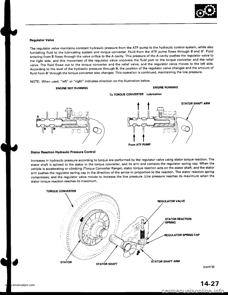
Regulator Valve
The regulator valve maintains constant hydraulic pressure from the ATF pump to the hydraullc control system, while also
furnishing fluid to the lubricating system and torque converter. Fluid from the ATF pump flows through B and B'. Fluid
entering from B flows through the valve orifice to the A cavity. This pressure of the A cavity pushes the regulator valve to
the right side. and this movement of the regulator valve uncovers the fluid port to the torque converter and the relief
valve. The fluid flows out to the torque converter and the relief valve, and the regulator valve moves to the left side.
According to the level of the hydraulic pressure through B, the position of the regulator valve changes and the amount of
fluid from B,through the torque converter also changes. This operation is continued, maintaining the line pressure.
NOTE; When used, "|eft" or "right" indicates direction on the illustration below.
ENGINE NOT RUNNING
STATOR SHAFT ABM
Stator Reaction Hydraulic Pressurs Control
Increases in hydraulic pressure according to torque are performed by the regulator valve using stator torque reaction. The
stator shaft is splined to the stator in the torque converter, and its arm end contacts the regulator spring cap When the
vehicle is accelerating or climbing (Torque Converter Range), stator torque reaction acts on the stator shaft, and the stator
arm pushes the regulator spring cap in the direction of the arrow in proportion to the reaction. The stator reaction spring
compresses, and the regulator valve moves to increase the line pressure. Line pressure reaches its maximum when the
stator torque reaction reaches its maximum.
TOROUE CONVERTER
REGULATON VALVE
STATOR REACTION
TOR SPRING CAP
(cont'd)
ENGINE RUNNING
To TOROUE CONVERTER Lubtication
STATONSTASHAFTATOF SHAFT ARM
14-27
www.emanualpro.com
Page 555 of 1395
Lock-up System
TOROUE CONVERTER
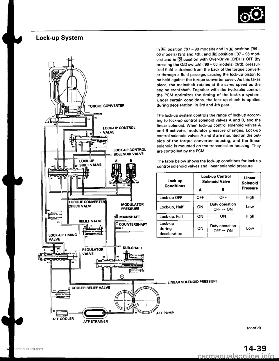
In E position ('97 - 98 models) and in E position ('99 -
OO models) (3rd and 4th), and E position ('97 - 98 mod-
els) and in E position with Over-Drive (O/D) is OFF (by
pressing the O/D switch) ('99 - 00 models) (3rd), pressur-
ized fluid is drained from the back of the torque convert-
er through a fluid passage, causing the lock-up piston to
be held against the torque converter cover, As this takes
Dlace, the mainshaft rotates at the same speed as th8
engine crankshaft. Together with the hydraulic control,
the PCM optimizes the timing of the lock-up system.
Under certain condltions. the lock-up clutch is appli€d
during deceleration, in 3rd and 4th gear.
The lock-up system controls the range of lock-up sccord-
ing to lock-up control solenoid valves A and B, and ths
linear solenoid. When lock-up control solenoid valves A
and B activate. modulator pressure changes. Lock-up
control solenoid valves A and B are mounted on the out-
side of the torque converter housing, and the linear
solenoid is mounted on the transmission housing. They
are controlled bv the PCM.
The table below shows the lock-up conditions for lock-up
control solenoid valves and linear solenoid pressure.
LINEAR SOLENOID PRESSURE
(cont'd)
LOCK.UP CONTROL' VALVE
LOCK.UP CONTROLSOLENOID VALVE
AB
MODULATORPf,ESSURE
MAINSHAFT
COUNTERSHAFT
SUB.SHAFT
Lock-up
Conditions
Lock-up Conirol
Solenoid valveLinaal
Solenoid
PrgssulsAB
Lock-up OFFOFFOFFHigh
Lock-up, HalfONDuty operation
OFF - ONLow
Lock-up, FullONONHigh
Lock-up
during
deceleration
ONDuty operation
OFF - ON
RELIEF VALVE
LOCK'UP TIMINGVALVE
COOLER RELIEF VALVE
ATF COOLERATF STRAINER
ATF PUMP
14-39
www.emanualpro.com
Page 670 of 1395
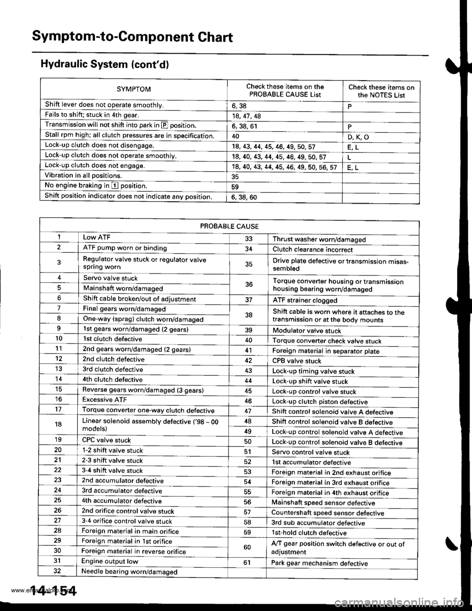
Symptom-to-Component Chart
Hydraulic System (cont'd)
SYMPTOMCheck these items on thePROBABLE CAUSE ListCheck these items onthe NOTES Lisr
Shift lever does not operate smoothly.o, JdPFails to shift; stuck in 4th gear.14, 41 , 48
Transmission will not shift into park in E position.6, 38, 61PStall rpm high; all clutch pressures are in specification.40D,K,OLock-up clutch does not disengage.18, 43, 44, 45, 46, 49,50,57
Lock-up clutch does not operate smoothly.14, 40, 43, 44, 45, 46, 49, 50. 57Lock-up clutch does not engage.'t8, 40, 43, 44, 45, 46, 49, 50, 56, 57Vibration in all positions.
No engine braking in I position.59
Shift position indicator does not indicate anv position,6. 38, 60
PROBABLE CAUSE
I 33 Thrust washer worn/damaged
ATF pump worn or binding34Clutch clearance incorrect
Regulator valve stuck or regulator valvespflng wornDrive plate delective or transmission mtsas-sembled
Servo valve stuck5ttTorque converter housing or transmissionhousing bearing worn/damagedMainshaft worn/damaged
Shift cable broken/out of adjustmentATF strainer clogged
7Final gears worn/damaged38Shift cable is worn where it attaches to thetransmission or at the body mountsIOne-way (sprag) clutch worn/damaged
1st gears worn/damaged {2 gears)39Modulator valve stuck10lst clutch defective40Torque converter check valve stuck112nd gears worn/damaged (2 gears)41Foreign material in separator plate't22nd clutch defectiveCPB valve stuck
t53rd clutch defective43Lock-up timing valve stuck144th clutch defective44Lock-up shift valve stucktcReverse gears worn/damaged (3 gears)Lock-up control valve stuck16Excessive ATF46Lock-up clutch Diston defective17Torque converter one-way clutch defective47Shift control solenoid valve A defecttve
18Linear solenoid assemblv defective (,98 - OOmodels)48Shift control solenoid valve B dsfectrve
49Lock-up control solenoid valve A defective'19CPC valve stuckLock-up control solenoid valve B deleqtve20l-2 shift valve stuck51Servo control valve stuck212-3 shift valve stuck52lst accumulator defective3-4 shift valve stuck53Foreign material in 2nd exhaust orifice2nd accumulator defective54Foreign material in 3rd exhaust orifice3rd accumulator defectiveForeign material in 4th exhaust orifice4th accumulator defective56Mainshaft speed sensor defective262nd orifice control valve stuckCountershaft speed sensor defective273-4 orifice control valve stuck583rd sub accumulator defective2aForeign material in main orifice59lst-hold clutch defective29Foreign material in lst orifice60A/T gear position switch defective or out ofadjustment30Foreign material in reverse orifice
31Engine output low61Park gear mechanism defective32Needle bearing worn/damaged
14-154
www.emanualpro.com
Page 672 of 1395

Symptom-to-Com ponent Chart
Hydraulic System (cont'd)
NOTES
See flushing procedure, page l4-264 and 265,
BSet idle rpm in gear to specified idle speed. lf still no good, adjust motor mounts as outlined in enginesection of this manual.
clf the large clutch piston O-ring is broken, inspect the piston groove for rough machining.
Dlf the clutch pack is seized or is excessively worn. inspect the other clutches fot wear, and check the orificecontrol valves, CPC valve, and linear solenoid for free movement.
lf the linear solenoid is stuck, inspect the clutches for wear.
lf the 1-2 shift valve is stuck closed. the transmission will not upshift. lf stuck open, the transmission hasno lst gear.
Hlf the 2nd orifice control valve is stuck, inspect the 2nd and 3rd clutch Dacks for wear.
lf the 3-4 orifice control valve is stuck, inspect the 3rd and 4th clutch packs for wear.
Jlf the clutch pressure control valve is stuck closed. the transmission will not shift out of lst gear.
Klmproper alignment of main valve body and torque converter housing may cause ATF pump seizure. Thesymptoms are mostly an rpm-related ticking noise or a high-pitched squeak.
Llf the ATF strainer is clogged with particles of steel or aluminum, inspect the ATF pump and differentialpinion shaft. lf both are OK and no cause for the contamination is found, replace the torque converter.
Mlf the lst clutch feed pipe guide in the end cover is scored by the mainshaft. inspect the ball bearing forexcessive movement in the transmission housing. lf oK, replace the end cover as it is dented. The o-rinounder the guide is probably worn.
N' Replace the mainshaft if the bushing for the 4th feed pipe is loose or damaged, lf the 4th feed pipe is darrFaged or out of round. replace the end cover.' Replace the mainshaft if the bushing for the l st feed pipe is loose or damaged. lf the 1st feed pipe is dam-aged or out of round, replace it.
oA worn or damaged sprag clutch is mostly a result of shifting the transmission in E!. E, or E positionwhile the wheels rotate in reverse. such as rocking the vehicle in snow.
PInspect the frame for collision damage.
lnspect for damage and wear:
l. Reverse selector gear teeth chamfers.
2. Engagement teeth chamfers of countershaft 4th and reverse gear.
3. Shift fork for scuff marks in center.
4. Differential pinion shaft for wear under pinion gears.
5. Bottom of 3rd clutch for swirl marks.
Replace items 1, 2, 3. and 4 if worn or damaged. lf transmission makes a clicking, grinding, or whirring noise,also replace mainshaft 4th gear, reverse idler gear, and countershaft 4th gear in addition to 1,2, 3, or 4.lf differential pinion shaft is worn, overhaul differential assembly, replace ATF strainer, and thoroughly cjeantransmission, flush torque converter. cooler, and lines,lf bottom of 3rd clutch is swirled and transmission makes gear noise. replace the countershaft and final drivenoear,
Be very careful not to damage the torque converter housing when replacing the main ball bearing. you
may also damage the ATF pump when you torque down the main valve body. This will result in ATF pumpseizure if not detected. Use the Drooer tools.
SInstall the main seal flush with the torque converter housing. lf you push it into the torque converterhousing until it bottoms out, it will block the fluid return passage and result in damage.
www.emanualpro.com