Gauge HONDA CR-V 1998 RD1-RD3 / 1.G Owner's Guide
[x] Cancel search | Manufacturer: HONDA, Model Year: 1998, Model line: CR-V, Model: HONDA CR-V 1998 RD1-RD3 / 1.GPages: 1395, PDF Size: 35.62 MB
Page 380 of 1395
Fuel Supply System
System Description
The fuel supply system consists of a fuel tank, in-tank
high-pressure fuel pump. PGM-Fl main relay, fuel filter,
fuel pressure regulator, fuel injectors, and fuel delivery
and return lines. This system delivers pressure-regulat-
ed fuel to the fuel injectors and cuts the fuel delivery
when the engine is not running.
Fuel Pressure
Relieving
Before disconnecting fuel pipes or hoses, release pres-
sure from the system by loosening the 12 mm banjo
bolt on the too of the fuel filter.
Do not smoke while working on the fuel system.
Ke€p open flames or sparks away from your work
area,
Be sure to relieve fuel pressure while the ignition
switch is off.
Write down the frequencies for the radio's preset
buttons.
Disconnect the battery negative cable from the bat-
tery negative terminal.
Remove the fuel fill cap.
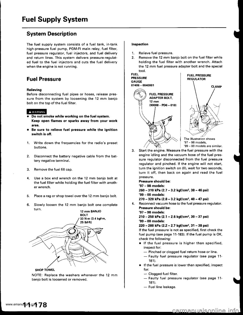
Use a box end wrench on the 12 mm banjo bolt at
the fuel filter while holding the fuel filter with anoth-
er wrench.
Place a rag or shop towel over the '12 mm banjo bolt.
Slowly loosen the 12 mm banjo bolt one complete
rurn 12 mm BANJoBOLT
1.
SHOP TOWEL
NOTE: Replace the washers whenever the 12 mm
banio bolt is loosened or removed.
11-178
Inspection
1, Relieve fuel pressure.
2. Remove the 12 mm banjo bolt on the fuel filter while
holding the fuel filter with another wrench. Attach
the 12 mm fuel pressure adapter bolt and the special
tool.
FUEL PRESSUREREGULATON
FUELPRESSUREGAUGE07406 - 0040001
The illustration shows'97 - 98 models,'99 - 00 models are similar.
Start the engine. Measure the fuel pressure with the
engine idling and the vacuum hose of the fuel pres-
sure regulator disconnected from the fuel pressure
regulator and pinched. lf the engine will not start,
turn the ignition switch on (ll), wait for two seconds,
turn it off, then back on again and read the fuel
pressure.
Pressure should be:'97 - 98 mod€ls:
260 -31O kPa 12.7 - 3.2 kgf/cm,, 38 - 46 psil'99 - 0O models:
270 - 32O kPa Q.A - 3.2 kgf/cm'�, ifo - /U psil
Reconnect vacuum hose to the fuel pressure regulator.
Prgs3ure should be:'97 - 98 models:
210 - 25O kPa 12.1- 2.6 kgf/cm'�, 30 - 37 psi)'99 - 00 models:
22O -26iJ kPa 12.2 - 2.7 kgt/cm'�, 31 - 38 psi)
lf the fuel pressure is not as specified, first check the
fuel pump (see page 11- 183). lf the fuel pump is OK,
check the following:
. lf the fuel pressure is higher than specified,
inspect for:- Pinched or clogged fuel return hose or line.- Faulty fuel pressure regulator (see page 11-
181).
. lf the fuel pressure is lower than specified. inspect
for:- Clogged fuel filter.- Faulty fuel pressure regulator (see page 11-
1811.- Fuel line leakage.
www.emanualpro.com
Page 383 of 1395
Fuel Pressure Regulator
Tesiing
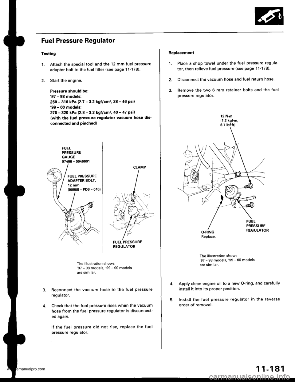
1. Attach the special tool and the 12 mm fuel pressure
adapter bolt to the fuel filter (see page 1l-178)
2. Start the engine.
Prasgure should be:'97 - 98 models;
260 - 310 kPa (2.7 - 3.2 kgl/cm'�,38 -,16 psi)'9!t - 00 models:
27O - 32o kPa l2-8 - 3.3 kgf/cm'�, 40 - /l7 psil
(with the lugl pressure rsgulator vacuum hose dis-
connested and pinched)
FUELPRESSUREGAUGE07406 - 0040001
FUEL PRESSURENEGULATOR
The illustration shows'97 - 98 models,'99 -00 modelsare similar.
Reconnect the vacuum hose to the fuel pressure
regulalor.
Check that the fuel pressure rises when the vacuum
hose from the fuel pressure regulator is disconnect-
ed agarn.
lf the fuel pressure did not rise, replace the fuel
pressure regulator.
4.
CLAMP
Replacement
'1. Place a shop towel under the fuel pressure regula-
tor, then relieve fuel pressure (see page 11-1781.
2. Disconnect the vacuum hose and fuel return hose.
3. Remove the two 6 mm retainer bolts and the fuel
pressure reguralor.
12 N.m(1.2 kgf.m,8.7 tbf.ft)
The illustration shows'97 - 98 models, '99 00 models
are similar.
Apply clean engine oil to a new O-ring. and carefully
install it into its proper position.
Install the fuel pressure regulator in the reverse
order of removal,
Replace.
1 1-181
www.emanualpro.com
Page 386 of 1395
Fuel Supply System
Fuel Gauge
Tssting
NOTE: Refer to section 23 for the fuel gauge system cir-cuit diagram.
'1. Check the No. 25 METER (7.5 A) fuse in the under-dash fuse/relay box before testing.
2. Fold the left rear seat cushion forward, and remove
the base frame cover {see section 20).
3. Remove the access panel from the floor.
4. Disconnect the 5P connector from the fuel pump.
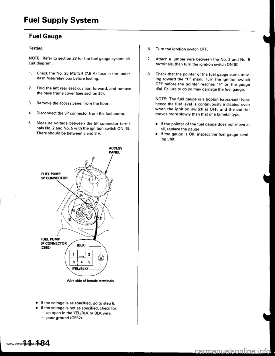
5. Measure voltage between the 5P connector termi-nals No.2 and No. 5 with the ignition switch ON ( ).There should be between 5 and 8 V.
FUEL PUMP5P CONNECTOR
tc56al
a
a
Wire side of female t€rminals
lf the voltage is as specified, go to step 6.lf the voltage is not as specified, check for:- an open in the YEUBLK or BLK wrre.- poor ground (c552).
11-184
7.
Turn the ignition switch OFF.
Attach a jumper wire between the No. 2 and No. 5terminals, then turn the ignition switch ON fll).
Check that the pointer of the fuel gauge starts mov-ing toward the "F" mark. Turn the ignition switchOFF before the pointer reaches "F" on the gauge
dial. Failure to do so may damage the luel gauge.
NOTE: The fuel gauge is a bobbin (cross-coil) type,hence the fuel level is continuously indicated evenwhen the ignition switch is OFF, and the pointer
moves more slowly than that of a bimetal type.
. lf the pointer of the fuel gauge does not move atall. replace the gauge.
. lf the gauge is OK, inspect the fuel gauge send-ing unit.
www.emanualpro.com
Page 387 of 1395
Fuel Gauge Sending Unit
Tgsting
@ Do not smoke while working on tho fuel
systom. Keop open flamo 8waY from your work araa.
1. Fold the left rear seat cushion forward, and remove
the base frame cover (see section 20).
2. Remove the access panel.
3. With the ignition switch OFF. disconnect the 5P con-
nector from the fuel pump.
4. Relieve fuel pressure (see page 11-178).
5. Disconnect the fuel lines.
6. Remove the fuel pump,
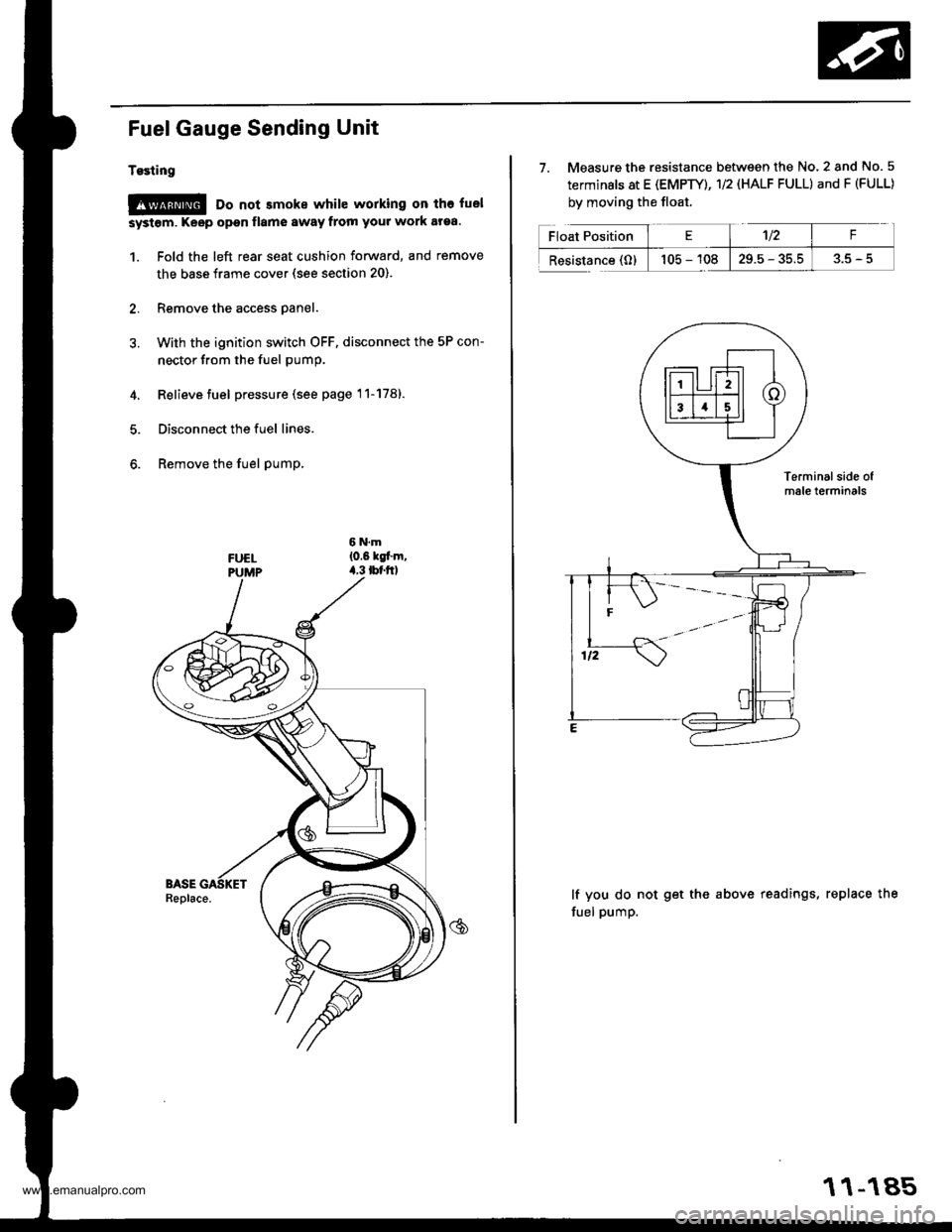
7. Measure the resistance between the No. 2 and No. 5
terminals at E (EMPTY), 1/2 (HALF FULL) and F (FULL)
by moving the float.
lf you do not get the above readings, replace the
fuel pump.
11-185
www.emanualpro.com
Page 388 of 1395
Fuel Supply System
Low Fuel Indicator System
Indicator Light Testing
NOTE: Refer to section 23forthe lowfuel lndicator circuit
clragram.
1. Check the No. 25 METER (7.5 A) fuse in the under-
dash fuse/relay box before testing.
2. Park the vehicle on level ground.
@ Do not smoke while working on the
fuel system. Keep open flame away trom the work
aroa. Drain fuel only into an approved container.
Drain the fuel into an aoDroved container. Then
install the drain bolt with a new washer.
Add less than 8 f (2.1 U.S. Gal. 1.8 lmp. Gal) of fuel,
and turn the ignition switch ON {ll). The low fuel indi-
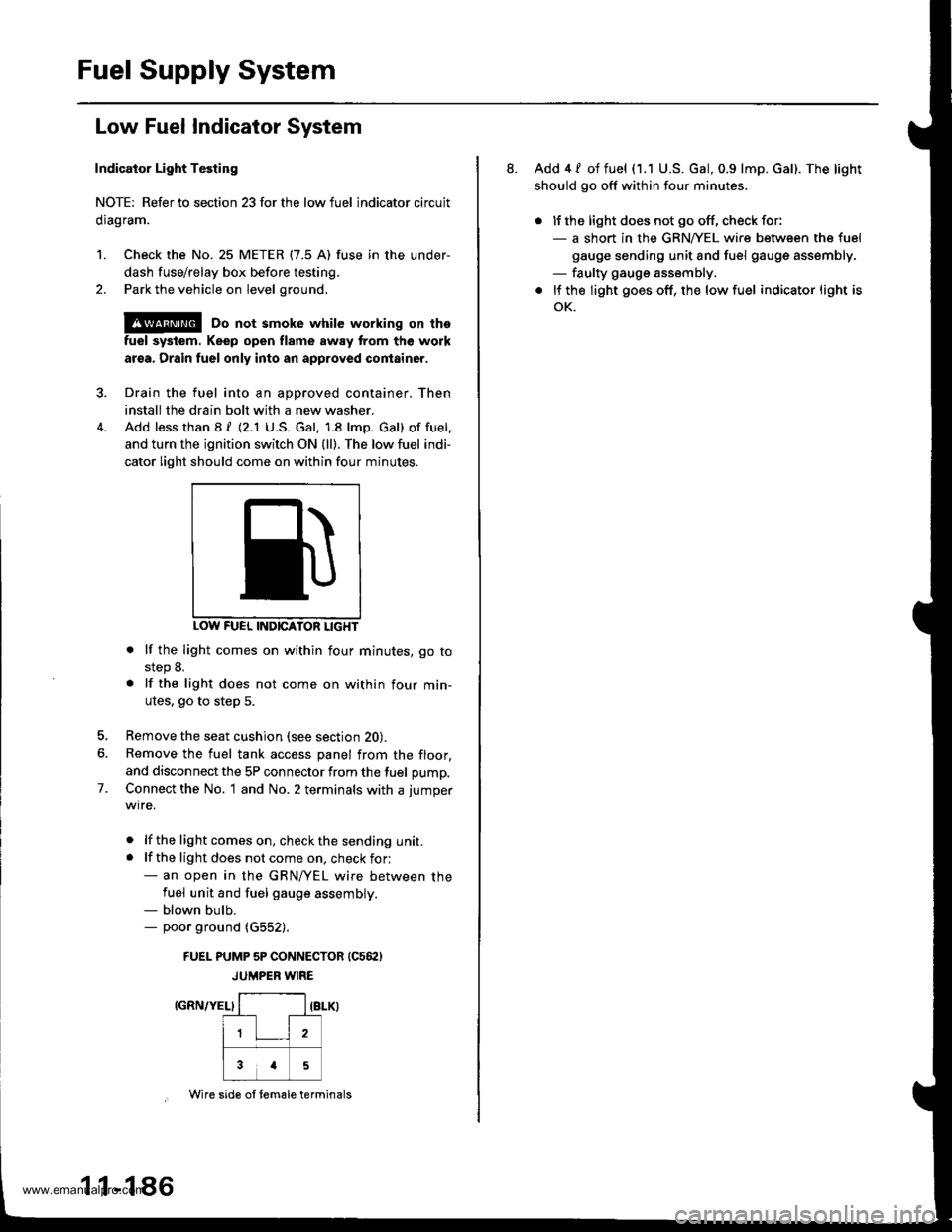
cator light should come on within four minutes.
INDICATON LIGHT
. lf the light comes on within four minutes, go tostep 8.
. lf the light does not come on within four min-
utes. go to step 5.
Remove the seat cushion (see section 20).
Remove the fuel tank access panel from the floor,
and disconnect the 5P connector from the fuel pump,
Connect the No. 1 and No. 2 terminals with a jumper
wire.
. lf the lightcomeson, checkthe sending unit.. lf the light does not come on, check for:- an open in the GRN/yEL wire between thefuel unit and fuel gauge assembly.- blown bulb.- poor ground (G552).
FUEI- PUMP 5P CONNECTOR (C562)
JUMPER WIRE
IGRN/YEL}
7.
1 1-1 86
Wire sid€ ol tem€le terminals
8. Add 4 / of fuel (1.1 U.S. Gal, 0.9 lmp. Gal). The light
should go off within four minutes.
. lJ the light does not go off, check for:- a short in the GRNA/EL wire between the fuel
gauge sending unit and fuel gauge assembly.- faulty gauge assembly.
. lf the light goes off, the low fuel indicator light is
oK.
www.emanualpro.com
Page 409 of 1395
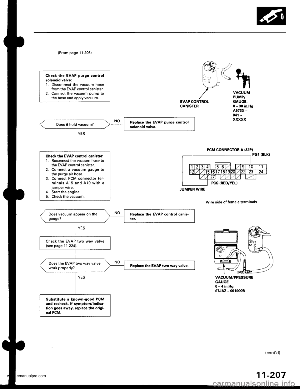
Chack iho EVAP purge controlsolenoid valve:1. Disconnect the vacuum hosetrom the EVAP controlcanister.2, Connect the vacuum pump tothe hose and apply vacuum,
Does it hold vacuum?
Chgck thg EVAP control csnbter:1. Reconnect the vacuum hose tothe EVAP control canister.2. Connect a vac!um gauge tothe purge air hose.3. Connect PCM connector terminals A15 and 410 with ajumper wire.4. Stan the engine.5. Check the vacuum.
Check the EVAP two way valve(see page 11'224).
Does the EVAP two way valvework properly?Rapbce the EVAP two wey valve.
Substitute a known-good PCMand rechock. It symptom/indica-tion gocs away, roplacg tho origi-nrl rcM.
(From page 11-206)
JUMPEF WIRE
<\
EVAP CONTNOLCANISTER
VACUUMPUMPIGAUGE,0-30 in.Hg4973X -
0il1 -
xxxxx
VACUUM/PRESSUREGAUGE0-4 in.Hg07JA2 - ml(x)o8
wire side of female terminals
{cont'd)
-20711
www.emanualpro.com
Page 410 of 1395
Emission Control System
Evaporative Emission (EVAP) Controls (cont'd)
99 - 00 models:
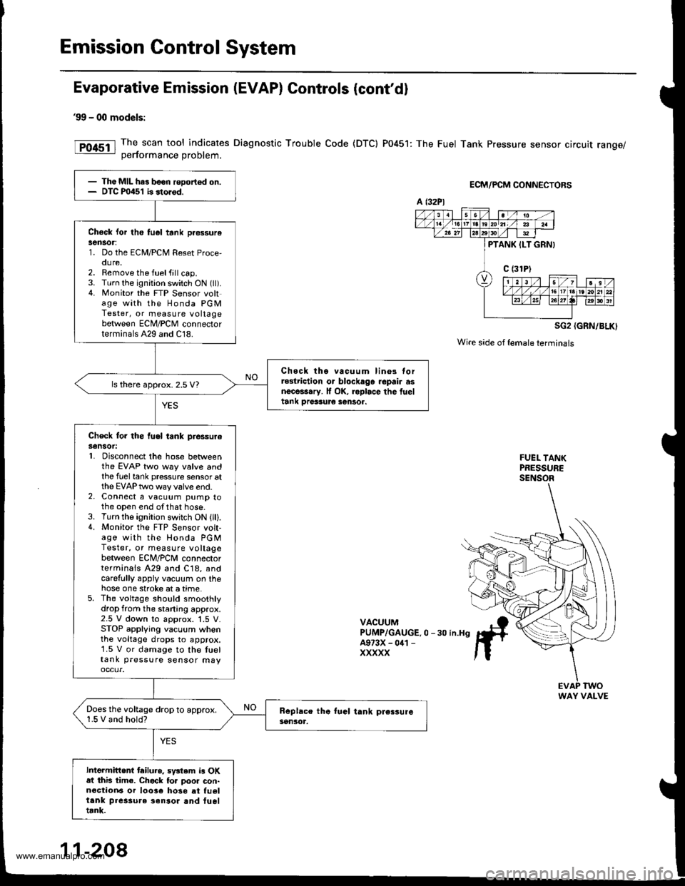
The scan tool indicates Diagnostic Trouble Code {DTC) P0451: The Fuel Tank Pressure sensor circuit range/oerformance Droblem.
ECM/PCM CONNECTORS
SG2 {GRN/BLK)
Wire side of {emaleterminals
FUEL TANKPRESSURESENSOR
VACUUMPUMP/GAUGE.0 -30 in.H9A973X - 041 -
XXXXX
- The MIL har been rooort€d on.- DTC P0451 b storod.
Check lor th6 tu6l tank pr€ssurelen30r:1. Do the ECM/PCM Reset Proce,oure.2. Remove the fuelfill cap.3. Turn the ignition switch ON (ll).4. Monitor the FTP Sensor voltage with the Honda PGMTester, or measure voltagebetween ECM/PCM connectorterminals A29 and C18.
Chock tho vacuum lin6s torrGlriction o. blockago repair asnecessary. lf OK, roplace the fueltank Drer3ur€ sentor.
ls there approx. 2.5 V?
Check for the fuel tank piessureSensot:L Disconnect the hose betweenthe EVAP two way valve andthe fuel tank pressure sensor atthe EVAP two way valve end.2. Connect a vacuum pump tothe open end ofthat hose.3. Turn the ignition switch ON (lll.4. Monitor the FTP S€nsor volt-age with the Honda PGMTester, or measure voltagebetween ECNI/PCNI connectorterminals A29 and C18, andcarefully appiy vacuum on thehose one stroke at a time.5. The voltage should smoothlydrop from the staning approx.2.5 V down to approx. 1.5 V.STOP applying vacuum whenthe voltage drops to approx.1.5 V or damage to the tueltank pressure sensor may
Does the voltage drop to approx.1.5 V and hold?
Intermittent tailuro. sv3tem is OKat this tim€. Chack to. poor con-n€ction6 or 10036 hose at fu6ltank pres3ure ionsor and fueltrnk.
a t32Pl
PTANK ILT GRNI
WAY VALVE
11-208
www.emanualpro.com
Page 416 of 1395
Emission Control System
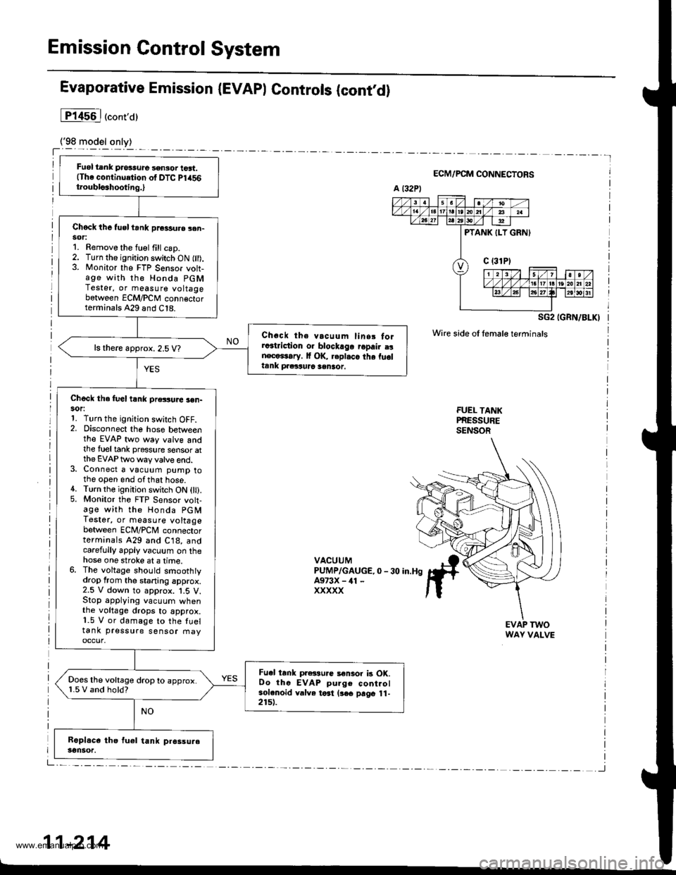
Fuel tank pros3ure sensor tost.(The continuetion of DTC Pl456t.oubls3hooting.,
Chock the tusl trnk pr€3sure sen-sor:1. Remove the fuel fill csp.2. Turn the ignition switch ON fll).3. Monitor the FTP Sensor voh-age with th€ Honda PGMTester, or measure voltagebetween ECM/PCM conn€ctorterminals A29 and C18.
Choct ths vacuum linsr forra3triction o. blockago ropair a!nect*rary. It OK, replaca the fu6ltank praituJc sentot.
ls there approx. 2.5 V?
Check the fuel t nk pressuae 3en-sor:1. Turn the ignition switch OFF.2. Disconnect the hose betweenthe EVAP two way valve andthe tueltank pressure sensor atthe EVAP two way valve end.3. Connect a vacuum pump tothe open end ofthat hose.4. Turn the ignition switch ON 0l).5. Monitor the FTP Sensor volt-age with the Honda PGMTestet, or measure voltagebetween ECM/PCM connectorterminals 429 and C18, andcarefully apply vacuum on thehose one stroke at a lime.6. The voltage should smoothtydrop from the staning approx.2.5 V down to approx. 1.5 V.Stop applying vacuum whenthe voltage drops to approx.1.5 V or damage to the fueltank pressure sensor fiayoccur,
Fu.l tank pressu.c a€nlor b OK.Oo thc EVAP pulge controlsolenoid valve toat (3€€ prgo 11-2151.
Does the voltage drop to approx.1.5 V and hold?
Evaporative Emission (EVAPI Controls (contd)
lP14s6l("ont,a)
ECM/PCM CONNECTORS
SG2 IGRN/BLKI
Wire side oI female terminals
FUEI- TANKPRESSURESENSOR
VACUUMPUMP/GAUGE,0 - 30 in.HgA973X - ill -
xxxxx
EVAP TWOWAY VALVE
11-214
www.emanualpro.com
Page 417 of 1395
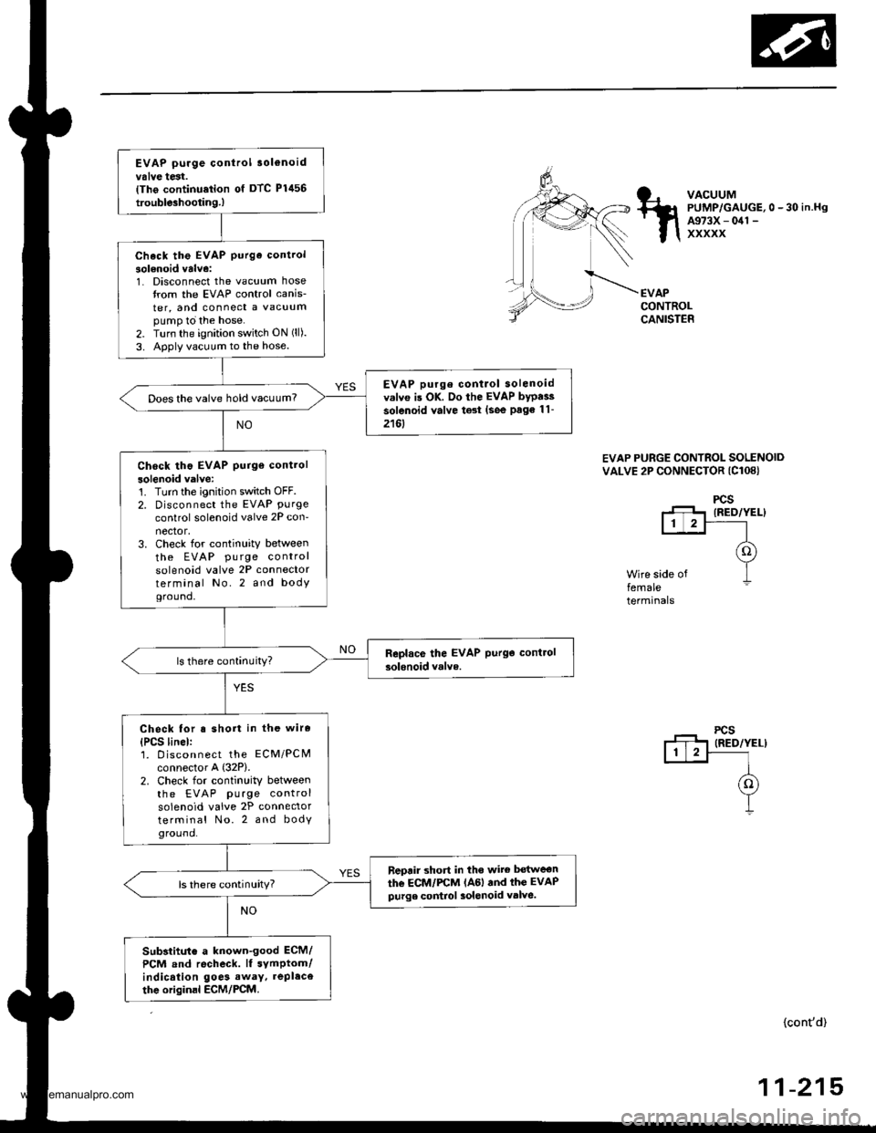
EVAP purge control 3ol€noidvalve test.{Tho continu.tion of DTC Plil56
trouble3hootin9.)
Check the EVAP purge control
solenoid valve:1. Disconnect the vacuum hosetrom the EVAP control canis-
ter, and connect a vacuumpump to the hose.2. Turn the ignition switch ON (ll).
3. Apply vacuum to the hose.
EVAP purge contlol solenoidv.lvo is OK. Do the EVAP bypai3
solenoid valve test (see Page 11-
2161
Does the valve hold vacuum?
Check tho EVAP purge control
solenoid valve:'t. Turn the ignition switch OFF.2. Disconnect the EVAP Purgecontrol solenoid valve 2P con-nector,3. Check for continuity between
the EVAP pu rge controlsolenoid valve 2P connectorterminal No.2 and bodYground,
Check for s short in the wire
{PCS linel:1. D iscon nect the ECM/PCMconnector A {32P).2. Check for continuity betweenthe EVAP purge controlsolenoid valve 2P connectorterminal No. 2 and bodyground.
neprir short in tho wite bot$reon
the ECM/FCM lAGl and thc EVAPpurge control 3olenoid valve.ls there continuity?
Substitut€ a known-good ECM/
PCM and recheck. lf symptom/indication goe3 away. repl.ce
thc originsl ECM/PCM.
VACUUMPUMP/GAUGE,0 - 30 in.HgA973X - 041 -
xxxxx
EVAPCONTROLCANISTER
EVAP PURGE CONTROL SOLENOIDVALVE 2P CONNECTOR (Cl08}
Wire side offemaleterminals
(cont'd)
-21511
www.emanualpro.com
Page 418 of 1395
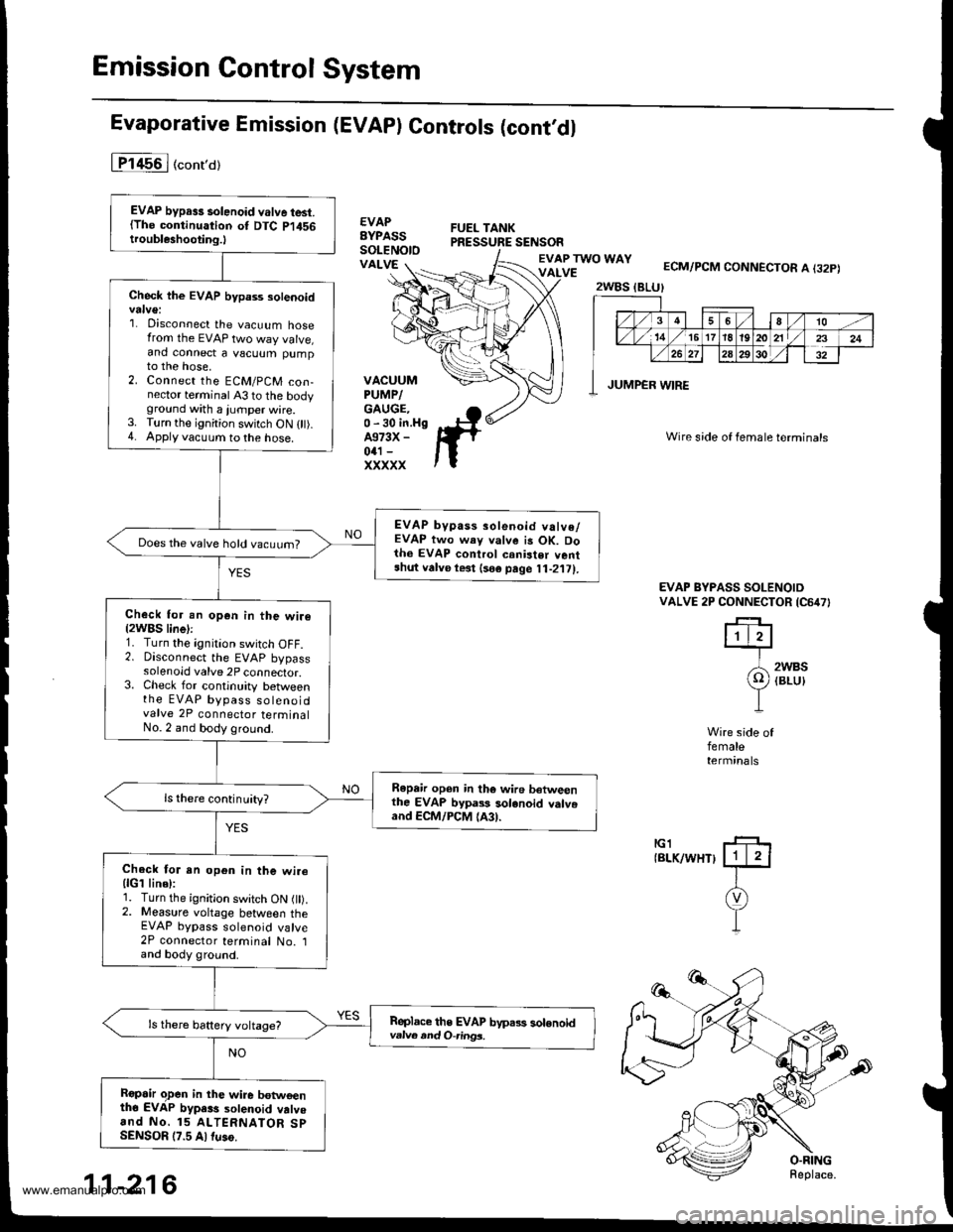
Emission Control System
Evaporative Emission (EVAPI Controls (cont,dl
1T1456I (conro)
€VAPBYPASSSoLENOtOVALVEECM/PCM CONNECTOR A I32P)
Wire side of female terminals
VACUUMPUMP/GAUGE.0 -30 in.HgA373X -
041 -
xxxxx
EVAP BYPASS SOLENOIDVALVE 2P CONNECTOR lcorlTl
2WBS(BLU}
II
Wire side offemaletermrnats
tGlIBLK/WHT}
EVAP bypa3s solenoid valve test.(The continuation ot DTC P1456troubleshooting.l
Check the EVAP bypass sotenoid
1. Disconnect the vacuum hosefrom the EVAP two way valve,and connect a vscuum pumpto the hose,2. Connect the ECM/PCM con-nector terminal 43 to the bodyground with a jurnper wire.3. Turn the ignition switch ON 0t).4. Apply vacuum to the hose.
EVAP bypass solenoid valve/EVAP two way valve is OK. Doth6 EVAP control crnister ventshut vafve le3t lso€ page 11-2'111.
Does the valve hold vacuurn?
Check for an op€n in the wir€(2WBS line):1. Turn the ignition switch OFF.2. Disconnect the EVAP bypasssolenoid valve 2P connector.3. Check for continuity betweenthe EVAP bypass so teno idvalve 2P connector terminalNo. 2 and body ground.
Repair open in the wire betweenthe EVAP bypass solenoid valv.and ECM/PCM lA3).
Chack tor an op6n in the wirellcl line):1. Turn the ignition switch ON l).2. Measure voltage between theEVAP bypass solenoid valve2P connector terminal No. land body ground.
Replace the EVAP byps.,s solonoidvatus and O-ring3.
Ropair o,pen in the wire botwoenth6 EVAP bypa$ sotenoid vatvoand No. 15 ALTERNATOR SpSENSOR (7.5 Altuso.
2WBS (BLU}
/3
7,x
4l6o/to -/
,/ 16 1718't920 211/z3
26 272A29solT32
JUMPER WIRE
11-216
www.emanualpro.com