Glass HONDA CR-V 1998 RD1-RD3 / 1.G Owner's Guide
[x] Cancel search | Manufacturer: HONDA, Model Year: 1998, Model line: CR-V, Model: HONDA CR-V 1998 RD1-RD3 / 1.GPages: 1395, PDF Size: 35.62 MB
Page 1022 of 1395
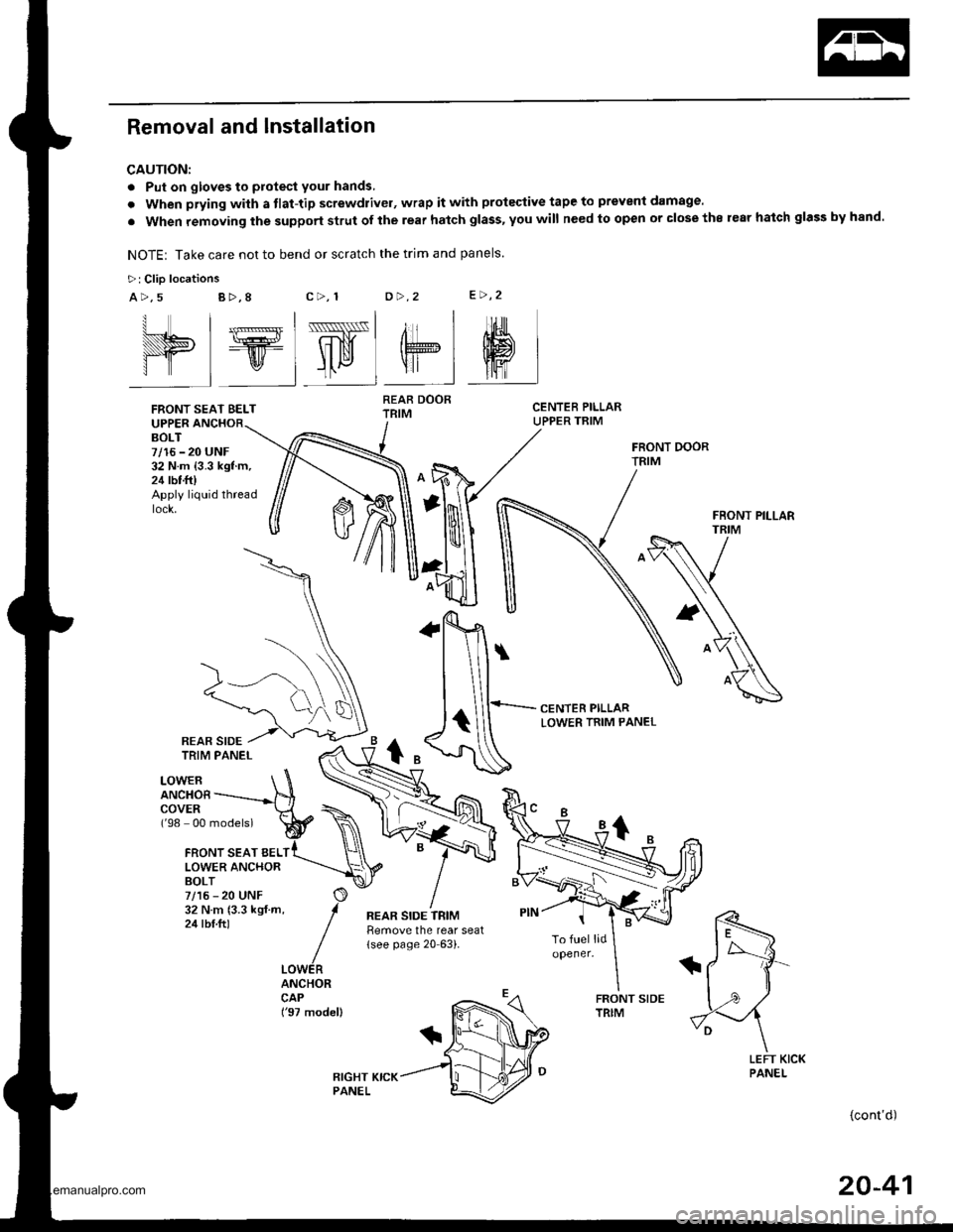
Removal and Installation
CAUTION:
. Put on gloves to protect your hands,
. When prying with a tlat-tip screwdrivel, wrap it with protective tape to prevent damage.
. When removing the support strut of the rear hatch glass, you will need to open or close the rear hatch glass by hand.
NOTE: Take care not to bend or scratch the trim and panels.
>: Clio locations
a>,5c>, 1o>.2e>,2B >,8
UPPERBOLT7/16 - 20 UNF32 N.m {3.3 kgf.m,24 rbt.ft)Apply liquid thread
CENTER PILLARLOWER TRIM PANEL
LOWERANCHOBCOVER('98 00 models)
{cont'd)
I l_lss-l , | 'rrl
elElw"lel sl
FRONT SEAT BELT
FRONT SEAT BELLOWER ANCHORBOLT7/15 - 20 UNF32Nm(3.3kgf.m,24 tbt.ftl
ANCHORCAP('97 model)
REAR DOORTRIM
REAR SIDE TRIMtlemove the rear seat(see page 20 63).
REAR SIDE
20-41
www.emanualpro.com
Page 1023 of 1395
Interior Trim
@wt we@M
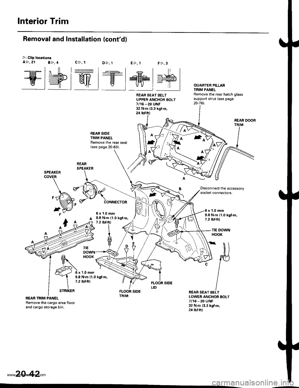
REAR SIOETRIM PANELRemove the reat seat(see page 20-63).
FCONNECTOR
2
OUARTER PILLARTNIM PANELRemove the rear hatch glasssupport strut (see page20-741.
Removal and Installation (cont'd)
>i Clip loc.tionsa>,21B>,4c>, 1E>. !F >,3D>, 1
Disconnect the accessorysocket connectors,
9.8 N.m (1.0 kgf.m,1.2lbt-lrl
5x1.0mm6x1.0mm9.8 N.m (1.0 kgtm,7.2 tbf ftl
TIE DOWNHOOK
6x1.0mm
TIEoowNHOOK
v
O\A
D
REAR SEAT BELTLOWER ANCHOR EOLT7/16 - 20 UNF32 N.m {3.3 kgt.m,24 tbl.frl
9.8 N.m (1.0 kgt m,7.2 tbf.ft)
REAR TRIM PANELRemove the cargo area floorand cargo slorage bin.
20-42
REAN SEAT BELTUPPER ANCHOR BOLT7/16-20 UNF32 N.m {3.3 kgt.m,24 rbt.ft)
REAR DOOR
REAR
ffi
STRIKER
www.emanualpro.com
Page 1025 of 1395
lnterior Trim
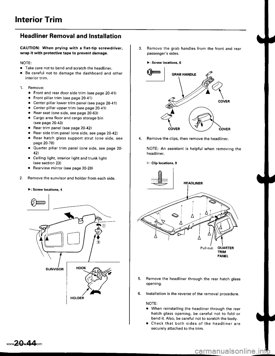
Headliner Removal and Installation
CAUTION: When prying with a tlat-tip screwdriver,
wrap it with protective tape to prevent damage.
NOTE:
. Take care not to bend and scratch the headliner.o Be careful not to damage the dashboard and other
interior trim.
1. Remove:
. Front and rear door side trim (see page 20-41). Front pillartrim (see page 20-41)
. Center pillar lower trim panel (see page 20-41). Center pillar upper trim (see page 20 41). Rear seat (one side, see page 20-63). Cargo area floor and cargo storage bin
{see page 20-43)
. Rear trim panel (see page 20-421
. Rear side trim panel (oneside, see page 20-42l,
. Rear hatch glass support strut (one side, seepage 20-78)
. Ouaner pillar trim panel {one side, see page 20-
42)
. Ceiling light, interior light and trunk light(see section 23)
. Rearview mirror (see page 20-28)
2. Remove the sunvisor and holder from each side.
>: Scaew location3, 4
I
A\"r- |Yr* || -
suNvtsoR
20-44
3. Remove the grab handles from
passenger's sides.
>r Screw locations, 6
the front and rear
ry_l
COVER
4. Remove the clips, then remove the headliner.
NOTE: An assistant is helpful when removing the
headliner.
>: Clip locations,9
HEADLINER
Pullout. OUARTERTRIMPANEL
5. Remove the headliner through the rear hatch glass
openrng.
6. Installation is the reverse of the removal procedure.
NOTE:
. When reinstalling the headliner through the rear
hatch glass opening, be careful not to fold or
bend it, Also, be careful not to scratch the body.. Check that both sides of the headliner are
securely attached to the trim.
www.emanualpro.com
Page 1029 of 1395
Dashboard
SRS components are located in this area. Review the SRS
component locations, precautions, and procedures in the
SRS section (24) before performing repairs or service.
GAUTION:
. When prying with a tlat-tip screwdriver, wrap h withproteqtive tape, and apply protective tape around the
relat€d parts, to prevent damage,
. Put on glovgs to protect your hands.
NOTE: Take care not to scratch the dashboard and relatedpans.
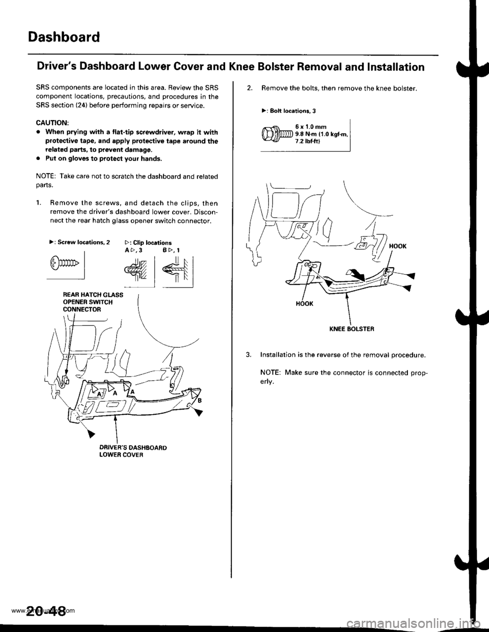
1. Remove the screws, and detach the clips, then
remove the driver's dashboard lower cover. Discon-
nect the rear hatch glass opener switch connector.
>: Clip locationsA >,3 B>, 1
rr.- | lr, l
@, | €{lr'" 1 |'l
>: Screw locations,2
IGlTtrrrb I.-l
REAR HATCH GLASSOPENER SWITCHCONNECTOR
20-48
'-
Driver's Dashboard Lower Cover and Knee Bolster Removal and Installation
2. Remove the bolts. then remove the knee bolster.
>: Boh locations,3
6x1.0mm9.8 N.m ('1.0 kgtm.7.2 tbtftl
3. Installation is the reverse of the removal procedure.
NOTE: Make sure the connector is connected prop-
erly.
KNEE BOLSTEF
www.emanualpro.com
Page 1059 of 1395
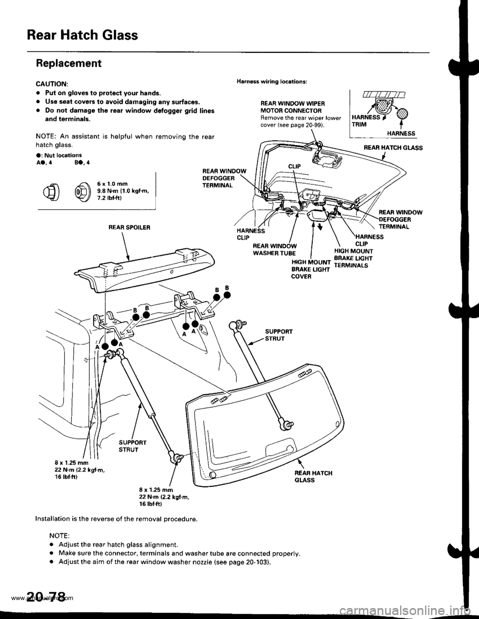
Rear Hatch Glass
Replacement
CAUTION:
. Put on gloves to protecl your hands.
. Use seal covers to avoid damaging any surfaces.. Do not damage the rear window delogger grid lines
and terminals.
NOTE: An assistant is helpful when removing the rear
hatch glass.
a: Nul locationsAa.4 Ba.4
€ @ i!iff*-"-
Harnoss wiring locations:
REAR WINDOW WIPERMOTOR CONNECTORRemove the rear wiper lowercover (see page 20-99i.
HARNESS 'TRIM
.;=-
8 x 1.25 mm22 N-m l'2.2 kgl.m,'16 tbt fr)
8 x 1.25 mm22N.m l.2.2*ql.m,16 tbf.ft|
Installation is the reverse of the removal orocedure.
NOTE:
. Adjust the rear hatch glass alignment.
. Make sure the connector, terminals and washer tube are connected properly.
. Adjust the aim of the rear window washer nozzle (see page 20-103).
20-78
REAR SPOILER
'--
www.emanualpro.com
Page 1060 of 1395
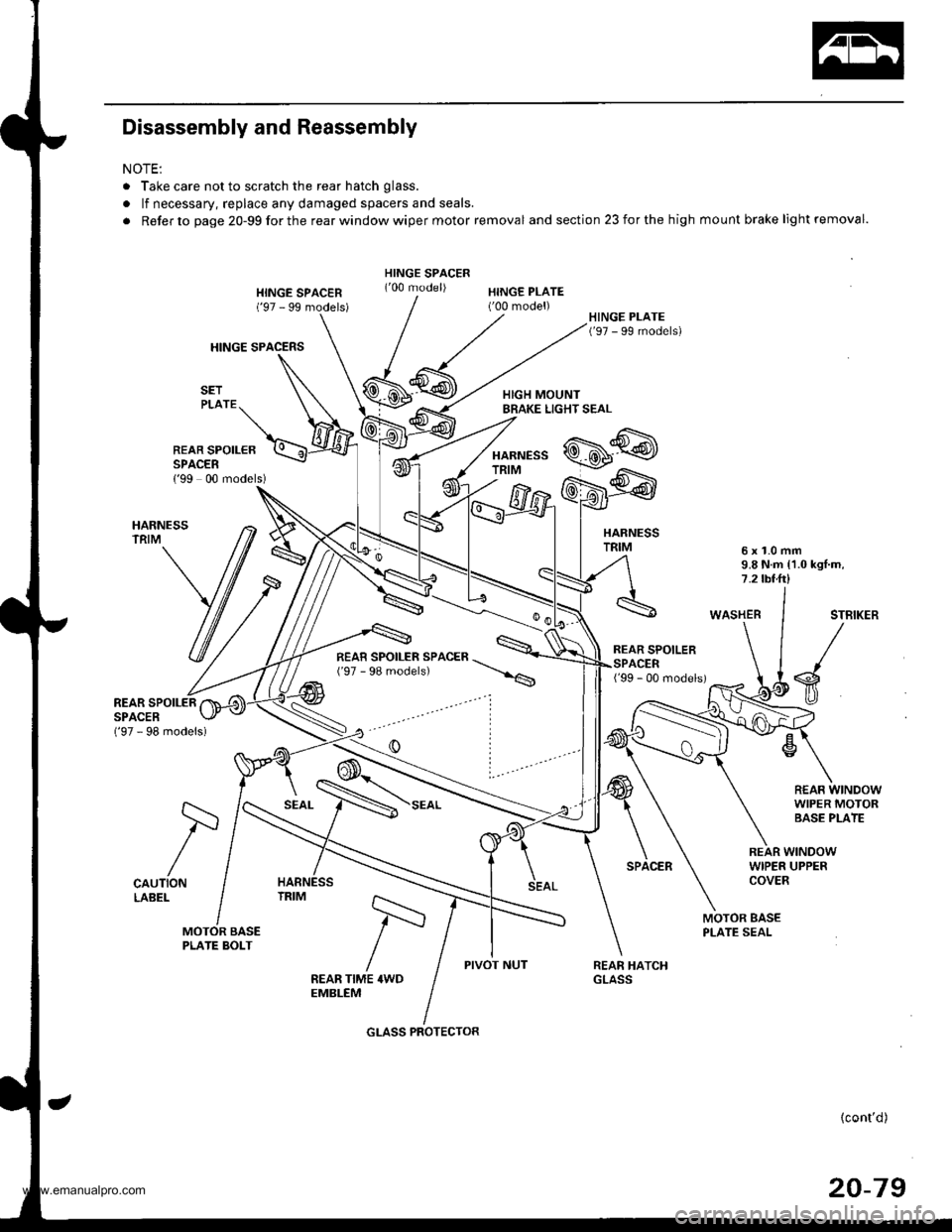
Disassembly and Reassembly
NOTE:
. Take care not to scratch the rear hatch glass.
. lf necessary, replace any damaged spacers and seals.
. Refer to page 20-99forthe rearwindowwiper motor removal and section 23 for the high mount brake light removal.
HINGE SPACERS
HINGE SPACEN('97 - 99 models)HINGE PLATE('00 model)
HARNESSTRIM
REAR SPOILEBSPACER{'99 00 models)
HARNESSTRIM6x1.0mm9.8 N.m {1.0 kgl.m,7.2 tbt.ft)
WASHERSTBIKER
s
R€AF WINDOWWIPER MOTORBASE PLATE
('97 - 98 models)
REAR SPOILERSPACER
CAUTIONLABEL
SEAL
REAR WINDOWWIPER UPPERCOVER
MOTOR BASEPLATE SEAL
PIVOT NUTFEAR TIME 4WDEMBLEM
{cont'd)
20-79
/=
GLASS PROTECTOR
www.emanualpro.com
Page 1061 of 1395
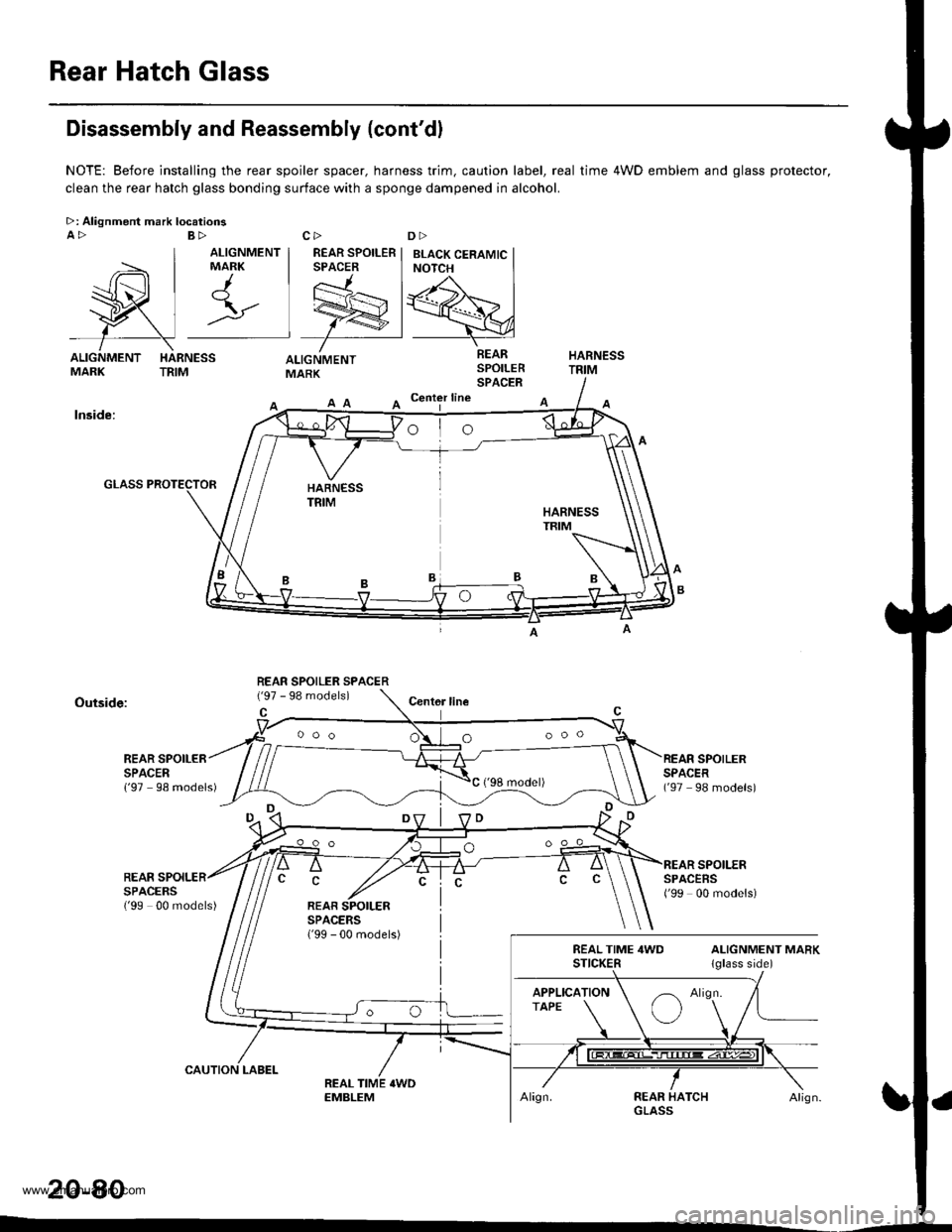
Rear Hatch Glass
l,_ | r\
wl:
f\ALIGNMENT HARNESSMARK TRIM
Disassembly and Reassembly (cont'dl
NOTE: Before installing the rear spoiler spacer, harness trim. caution label, real time 4WD emblem and glass protector,
clean the rear hatch glass bonding surface with a sponge dampened in alcohol.
>: Alignment mark locatioosA>
ALIGNMENTMARK
A Center line
lnside:
Outside:Centor line
REAR SPOILERSPACER{'97 98 models)
SPOILERREARSPACEBSSPACERS('99 00 models){'99 00 models)
20-80
REAR SPOILER SPACER
ooo O
www.emanualpro.com
Page 1062 of 1395
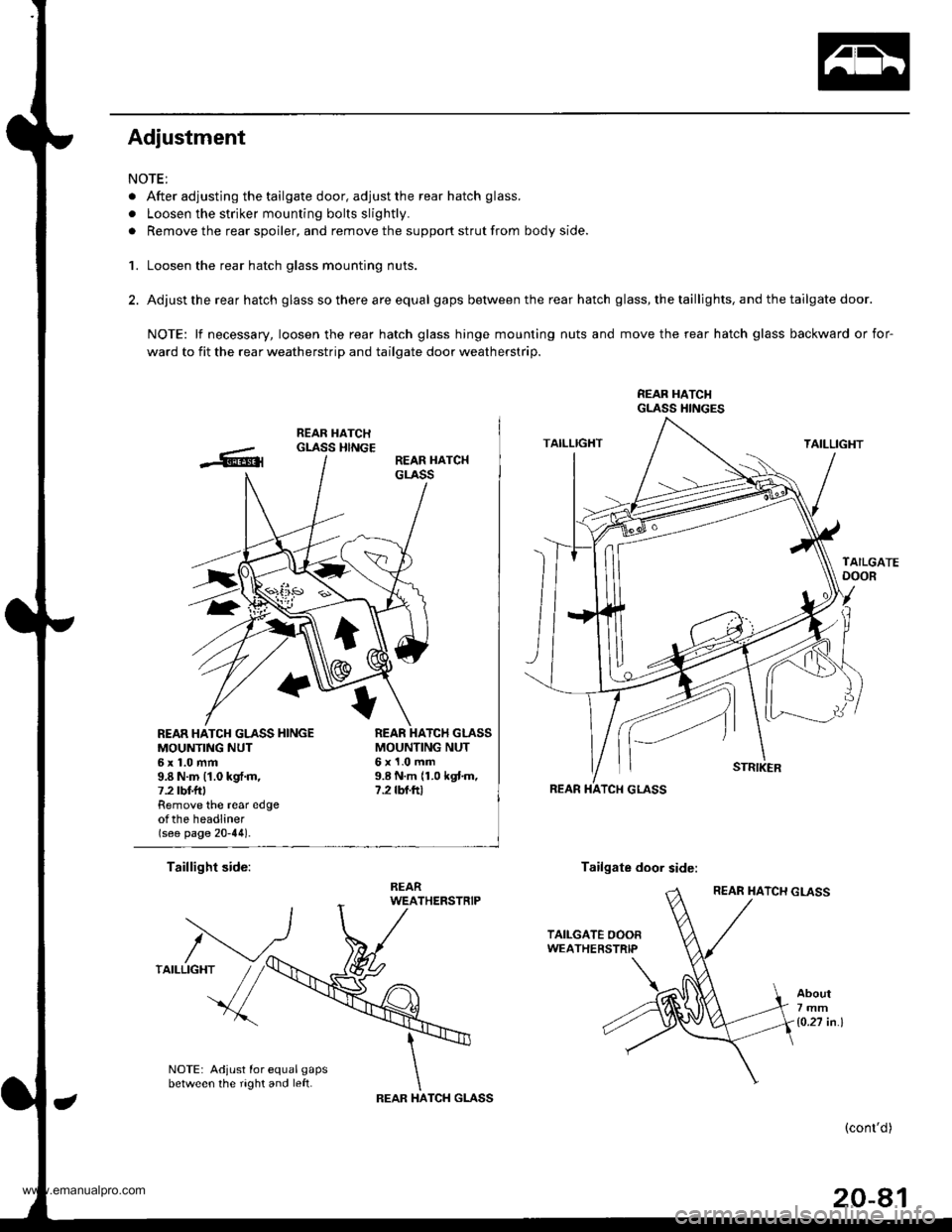
Adjustment
NOTE:
. After adjusting the tailgate door, adjust the rear hatch glass.
. Loosen the striker mounting bolts slightly.
. Remove the rear spoiler, and remove the support strut from body side.
1. Loosen the rear hatch glass mounting nuts.
2. Adjust the rear hatch glass so there are equal gaps between the rear hatch glass, the taillights, and the tailgate door.
NOTE: lf necessary, loosen the rear hatch glass hinge mounting nuts and move the rear hatch glass backward or for-
ward to fit the rear weatherstrip and tailgate door weatherstrip.
REAR HATCI{GLASS HINGES
REAR HATCH GLASS HINGEMOUNTING NUT6x1.0mm9.8 N.m (1.0 kgf.m,7.2 tbt f Remove the rear edgeotthe headliner(see page 20-44).
MOUNTING NUT6x1.0mm9.8 N.m 11.0 kgtm,7.2 rbf.ftt
Taillight side:Tailgate door side:
About7mm
1o.27 in.l
NOTE: Adjust for equal gapsbetween the right and left.TCH GLASSIHAREAR
(cont'd)
20-81
www.emanualpro.com
Page 1063 of 1395
Rear Hatch Glass
3.
4.
Adjustment (cont'dl
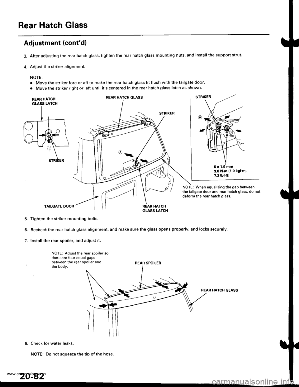
After adjusting the rear hatch glass, tighten the rear hatch glass mounting nuts, and installthe support strut.
Adjust the striker alignment.
NOTE:
. Move the striker fore or aft to make the rear hatch glass fit flush with the tailgate door'
. Move the striker right or left until it's centered in the rear hatch glass latch as shown.
REAR HATCHGLASS LATCH
STRIKER
NOTE: When equalizing the gap betweenthe tailgate door and rear hatch glass, do notdglorm the rear hatch glass.
TAILGATE DOOR
5. Tighten the striker mounting bolts.
6. Recheck the rear hatch glass alignment. and make sure the glass opens properly, and locks securely.
7. Installthe rear spoiler. and adjust it.
NOTE: Adjust the rear spoiler sothere are four equal gaps
between the rear spoiler andthe body.REAR SPOILER
REAR HATCH GLASS
8. Check for water leaks.
NOTE: Do not squeeze the tip of the hose.
20-82
REAR HATCH GLASS
6x1.0mm9.8 N.m (1.0 kgt'm,
7.2tbl.ftl
www.emanualpro.com
Page 1080 of 1395
Rear Window Wiper Arm and
Motor Replacement
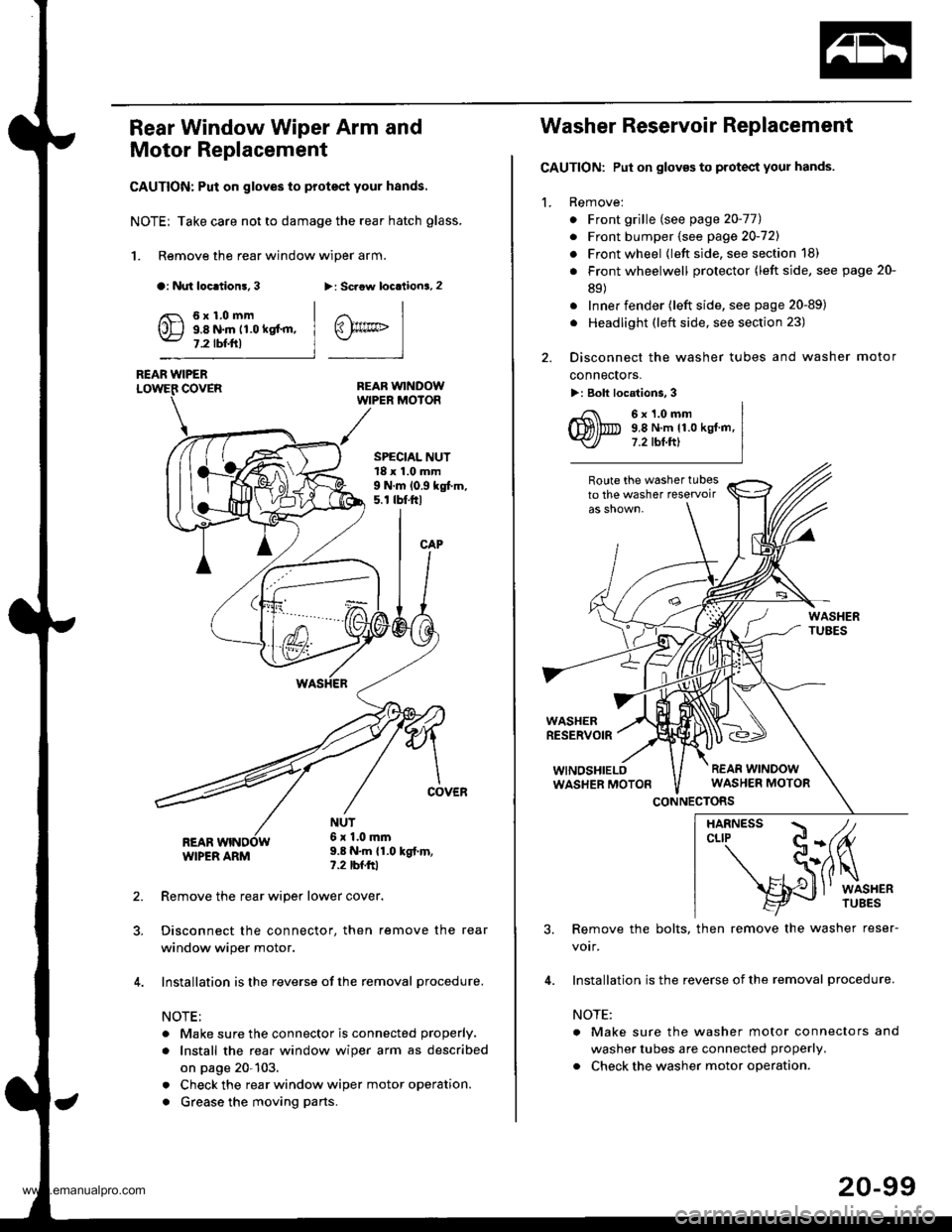
CAUTION: Put on gloves to protect your hands.
NOTE; Take care not to damage the rear hatch glass.
1. Remove the rear window wiper arm.
a: Nut loc.tion!, 3>: Scaow locationa, 2
REAR WINDOWWIPER MOIOR
REAR WIPERCOVER
REARWIPER ARM
6x1.0mm9.8 N.m 11.0 kgt'm,7.2 tbf.ftl
SPECIAL NUT18 x 1.0 mm9 N.m 10.9 kgt m,5. r tbt.ftl
NUT6x 1.0mm9.8 N.m {1.0 kgt.m,?.2 tbfftl
Remove the rear wiper lower cover.
Disconnect the connector, then remove the rear
window wiper motor.
Installation is the reverse of the removal procedure.
NOTE:
. Make sure the connector is connected properly.
. Install the rea. window wiper arm as described
on page 20-103.
. Check the rear window wiper motor operation.
. Grease the moving parts.
@rrc
Washer Reservoir Replacement
GAUTION: Put on gloves to protect your hands.
1. Remove:
. Front grille (see page 20-771
. Front bumper (see page 20-721
. Front wheel {left side, see section 18)
. Front wheelwell protector (left side, see page 20-
89)
. Inner fender (left side, see page 20-89)
. Headlight (left side, see section 23)
2. Disconnect the washer tubes and washer motor
connectors.
>: Bolt locations, 3
6x1.0mm9,8 N.m 11.0 kgt.m,7.2 tbt.ftl
Route the washer tubesto the washer teservoir
WASHERRESERVOIR
WINOSHIELOWASHER MOTON
CONNECTORS
3. Remove the bolts, then remove the washer reser-
votr,
4. Installation is the reverse of the removal procedure.
NOTE:
a Make sure the washer motor connectors and
washer tubes are connected properly.
. Check the washer motor operation.
HARNESS / tcLrP C-(fu
- S(ilq
s{J
l' wrsHER
20-99
www.emanualpro.com