Glass HONDA CR-V 1998 RD1-RD3 / 1.G Service Manual
[x] Cancel search | Manufacturer: HONDA, Model Year: 1998, Model line: CR-V, Model: HONDA CR-V 1998 RD1-RD3 / 1.GPages: 1395, PDF Size: 35.62 MB
Page 1082 of 1395
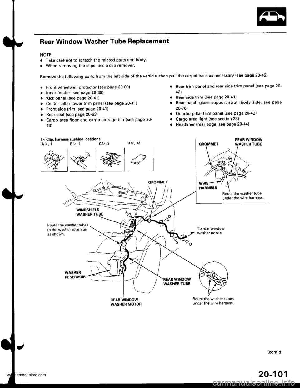
Rear Window Washer Tube Replacement
NOTE:
. Take care not to scratch the related parts and body.
. When removing the clips, use a clip remover.
Remove the following parts from the left side of the vehicle, then
. Front wheelwell protector (see page 20-89)
. Innertender (see page 20-89)
. Kick panel (see page 20-4't)
. Center pillar lower trim panel (see page 20-41)
. Front side trim (see page 20-41)
. Rear seat (see page 20-63)
a Cargo area floor and cargo storage bin (see page 20-
43)
>: Clip, harness cu3hion location3c>,3D>,12A>, 1B>, 1
Route the washer t!be
under the wire harness
Route the washer tubesto the washer reservoir
WASHEBRESERVOIR
wasner no2zre.
@s_l el 4
WINDSHIELDWASHEB TUBE
REAR WINDOWWASHER MOTOR
GROMMET
wrNoowWASHER TUBE
pull the carpet back as necessary (see page 20-45)
. Rear trim panel and rear side trim panel (see page 20-
42J
. Rear side trim (see page 20-41)
. Rear hatch glass support strut (body side, see page
20-7Al
. Ouarter pillartrim panel (see page 20-421
o Cargo area light (see section 23)
. Headliner (rear edge, see page 20-44)
GROMMET
(cont'd)
20-101
www.emanualpro.com
Page 1084 of 1395
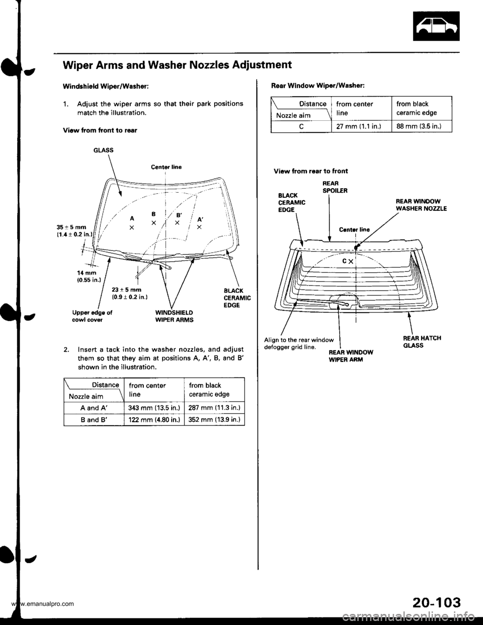
Wiper Arms and Washer Nozzles Adiustmenl
Wind3hield Wipor/Washer:
1, Adiust the wiper arms so that their park positions
match the illustration.
Viow from flont io roar
GLASS
2. Insert a tack into the washer nozzles. and
them so that they aim at positions A, A', B,
shown in the illustration.
adjust
and B'
Distance
^,J;-ll\
from center
line
from black
ceramic edge
A and A'3,$ mm (13.5 in.)287 mm (11.3 in.)
B and B'122 mm (4.80 in.)352 mm (13.9 in.)
Rear Window wipor/Washer:
Vi6w trom roar to lront
REARsPo[.-ER
C.nlar linoL
Align to the rear windowdefogger grid line.
Distance
ru"rrr. "i.
'_\from center
ltne
from black
ceramic edge
27 mm (1.1 in.)88 mm (3.5 in.)
20-103
www.emanualpro.com
Page 1148 of 1395
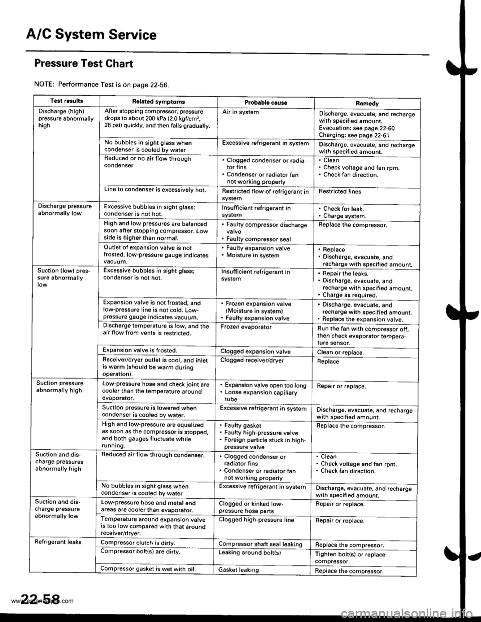
A/C System Service
Pressure Test Chart
NOTE: Performance Test is on page 22-56.
Test resultsRelatad symptomsPrcbable caus€Remody
Discharge (high)pressure 6bnormallyhagh
After stopping compressor, pressuredrops to about 200 kPa 12.0 kgtlcm,,28 psi) quickly, and then lalls gradualty.
Air in systemDischarge, evacuate, and rechargewith specified amount.Evacuation: see page 22-60Charging: see page 22-61No bubbles in sight glass whencondenser is cooled by waterExcessive refrigerant in systemDischarge, evacuate, and rechargewith specilied amount.Reduced or no air flow throughcondenser. Clogged condenser or radia-tor fins. Condenser or radiator fannot wo.king properly
CleanCheck voltage and fan rpm.Check fan direction.
Line to condensor is excossivelv hot.Restricted flow of relrigerant insy$emFestricted lines
Discharge pressureabnormally lowExcessive bubbles in sight glass;condenser is not hot.Insufficient retrigerant inCheck for leak.Charge system.High and low pressures are balancedsoon after stopping compressor. Lowside is higher than normal.
. Faulty compressor discharge
. Faulty compressor seal
Replace the comprossor.
Outlet ot expansion valve is notfrosted, low-pressure gauge indicates
' Faulty expansion valve. Moisture in system. Replace. Discharge, evacuate, andrecharge with specified amount.Suction {low) pros,sure abnormallyExcessive bubbles in sight glass;condenser is not hot.Insufficiont relrigerant inRepair the leaks.Discharge, evacuate, andrecharge with specified amount.Charge as r€quired.Expansion valve is not frosted, andlow-pressure line is not cold. Low-pressure gauge indicates vacuum.
' Frozen expansion valvelMoisture in system). Faulty expansion valve
. Discharge, evacuate, andrecharge with specitied amount.. Replace th€ expansion valve.Discharge temperature is low, and theair llow trom vents is restricted.Frozen evaporatorRun the fan with compressor off,then check evaporator tempera,ture sensor.Expansion valve is frosted.Clogged expansion valveClean or replace.Feceiver/dryer outlet is cool, and inlotrs w6rm (should be warm duringoperation).
Clogged receiver/dryerReplace
Suction pressureabnormally highLow-pressure hose and check joint arecooler than tho temperature aroundevaporator.
. Expansion valve open too long. Loose expansion capillarytube
Repair or roplace.
Suction pressure is lowored whencondenser is cooled by water.Excessive refrigerant in systemDischarge, evacuate, and rechargewath specified amount.High and low-pressure are equalizedas soon as tho compressor is stopped,and both gauges tluctuate whilerunning.
Faulty gasketFaulty high-pressure valveForeign panicle stuck in high-
Replace the compressor.
Slction and dis,charge pressutesabnormally high
Reduced air flow through condens€r,. Clogged condenser orradiator tins. Condenser or radiator fannot working properly
CleanCheck voltage and fan rpm.Check Ian direction.
No bubbles in sight glass whencondenser is cooled by walerExcessive refrigerant jn systemDischarge, evacuate, and rechargewith specified amount.Suction and dis-charge pressureabnormally low
Low-pressure hose and motalendareas are cooterlhan evaporator.Clogged or kinked low-pressure hose pansRepair or replace.
Temperature around expansion valvers too low compared with that aroundClogged high-pressure lineRepair or replace.
Refrigerant leaksCompressor clutch is diny.Compressor shaft seal leakingReplace the compressor.Compressor boltls) are dirty.Leaking around bolt(s)Tighton bolt{s) or replacecompressor.Compressor gasket is wet with oil.Gasket leakingReplace the compressor,
www.emanualpro.com
Page 1184 of 1395
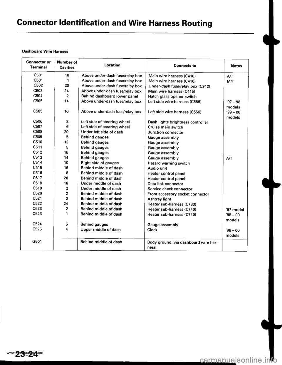
Connector ldentification and Wire Harness Routing
Dashboard Wire Harness
Connector ol
Terminal
Numb€r of
CavitiesLocationConngcts toNotes
c501
c501
c502
c503
c504
c505
c506
c507
c508
c509
c510
c511
c512
c514
c518
c519
c520
c521
c524
10
1
20
14
16
6
20
13
5
t6
14
10
to
20
16
2
24
2
1
5
Above under-dash fuse/relay box
Above under-dash fuse/relay box
Above under-dash fusehelay box
Above under-dash fuse/relay box
Behind dashboard lower panel
Above under-dash fuse/relay box
Above under-dash fuse/relay box
Left side of steering wheel
Left side of steering wheel
Under left side of dash
Behind gauges
Behind gauges
Behind gauges
Behind gauges
Behind gauges
Right side of gauges
Behind middle of dash
Behind middle of dash
Behind middle of dash
Under middle of dash
Under middle of dash
Behind middle of dash
Behind middle of dash
Behind middle of dash
Behind middle of dash
Behind middle of dash
Behind gauges
Upper middle of dash
Main wire harness (C416)
Main wire harness (C416)
Under-dash fuse/relay box 1C912)
Main wire harness (C415)
Hatch glass opener switch
Left side wire harness (C556)
Left side wire harness (C556)
Dash lights brightness cont.oller
Cruise main switch
Junction connector
Gauge assembly
Gauge assembly
Gauge assembly
Gauge assembly
Gauge assembly
Hazard warning switch
Audio unit
Heater control panel
Heater control panel
Data link connector
Service check connector
Front accessory socket connector
Ashtray light
Heater sub-harness (C733)
Heater sub-harness {C740}
Heater sub-harness (C740)
Gauge assembly
Clock
'97 - 98
models'99 - 00
models
Mir
A/r
'97 model'98 - 00
mooets
'98 - 00
models
G501Behind middle of dashBody ground, via dashboard wire har-
ness
23-24
www.emanualpro.com
Page 1188 of 1395
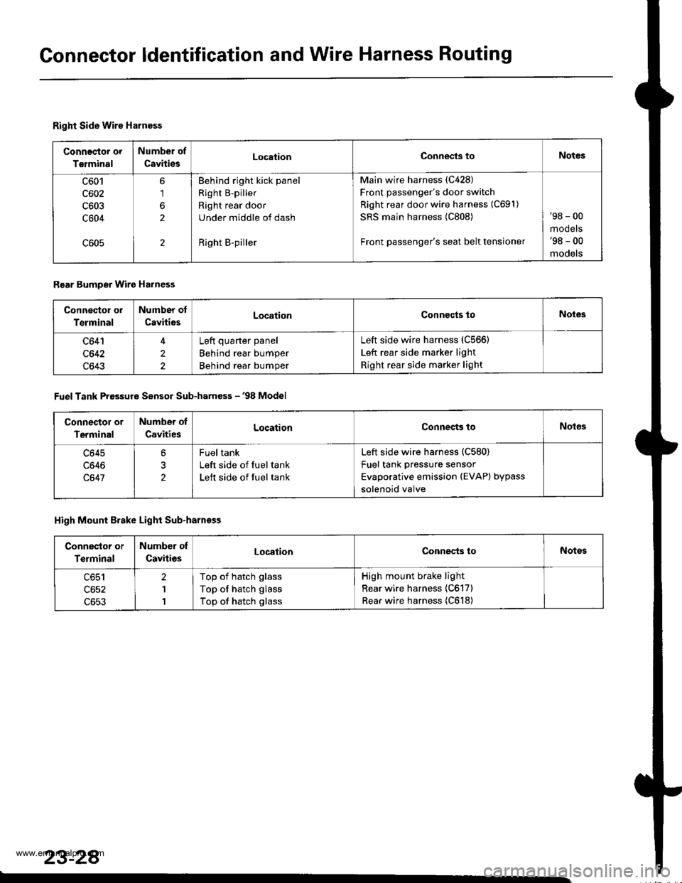
Gonnector ldentification and Wire Harness Routing
Right Side Wire Harness
Connec{or or
Tsrminal
Number of
CavitiesLocationConnests toNotes
c601
c602
c603
c604
6'1
2
2
Behind right kick panel
Right B-piller
Right rear door
Under middle of dash
Right B-piller
Main wire harness (C428)
Front passenger's door switch
Right rear door wire harness (C691)
SRS main harness {C808)
Front passenger's seat belt tensioner
'98 - 00
mooets'98 - 00
models
Rear Bumper Wire Harness
Connector ol
Terminal
Number ot
CavitiesLocationConnocts toNotes
c641
c642
c643
4
2
2
Left quarter panel
Behind rear bumper
Behind rear bumper
Left side wire harness (C566)
Left rear side marker light
Right rear side marker light
Fuel Tank Pressure Sensor Sub-harness - '98 Model
Connector or
Terminal
Number ot
CavitiesLocationConnects toNot63
c645
c646
c647
?
2
Fueltank
Left side of fuel tank
Left side of fuel tank
Left side wire harness (C580)
Fuel tank pressure sensor
Evaporative emission (EVAP) bypass
solenoid valve
High Mount Brake Light Sub-harnoss
Conneslor or
Terminal
Number of
CavitiesLocationConnec-ts toNotes
c651
c652
c653
2
1
1
Top of hatch glass
Top of hatch glass
Top of hatch glass
High mount brake light
Rear wire harness (C617)
Rear wire harness (C618)
23-28
www.emanualpro.com
Page 1190 of 1395
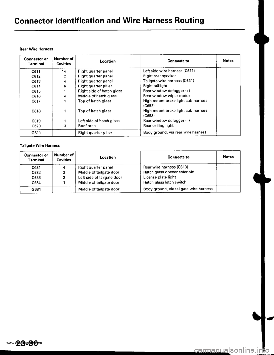
Gonnector ldentification and Wire Harness Routing
Rear Wiro Harness
Connector or
Terminal
Number of
CavitiesLocationConnects toNotes
c61l
c612
c613
c614
c617
c618
c619
c620
14
2
6
1
1
'I
1
Right quarter panel
Right quarter panel
Right quarter panel
Right quaner piller
Right side of hatch glass
Middle of hatch glass
Top of hatch glass
Top of hatch glass
Left side of hatch glass
Roof area
Left side wire harness (C57'l)
Right rear speaker
Tailgate wire harness (C631)
Right taillight
Rear window defogger (+)
Rear window wiper motor
High mount brake light sub-harness
(c652)
Hjgh mount brake light sub-harness
{c653)
Rear window defogger (-)
Rear ceiling light
G611Right quarter pillerBody ground, via rear wire harness
Tailgate wire Harness
Connestor or
Terminal
Number of
CavitiesLocationConnects toNoles
c633
c634
2
2
1
Right quarter panel
Middle of tailgate door
Left side of tailgate door
Middle of tailgate door
Rear wire harness (C613)
Hatch glass opener solenoid
License plate light
Hatch glass latch switch
I/iddle of tailgate doorBody ground, via tailgate wire harness
23-30
www.emanualpro.com
Page 1203 of 1395

Power Distribution
Fuse-to-Gomponent(sl Index (numerical sequence)
Under-hood Fuse/Rolay Box:
41
43
44
46
47
48
49
50
52
Capacity
'100 A
40A
7.5 A
15 A
40A
7.5 A
30A
204
204
15 A
10A
40A
40A
204
20A
Capacity
40A
204
7.5 A
wiro ColorFuseCircuit(s) Prot€cted
A
lgnition switch (BAT)
lntegrated control unit
Ceiling lights
Spotlights
PGM-Fl main relay
Not used
No. 7, 8, 10, 11 fuse in the under-dash fuse/relay box
Audio unit
Clock {'98 - 00 models)
Data link connector ('98 - 00 models)
ECM (VBU) {'98 - 00 models: M/T)
Heater control panel
PCM (VBU) (A./T)
Combination light switch (via under-dash fuse/relay box)
No. 20, 33 fuse in the under-dash fuss/relay box
Not used
Rear window defogger (via relay)
Door lock control unit
Hatch glass opener solenoid
Keyless door lock control unit ('98 - 00 models)
Horn relay
Horns (via relay)
via brake switch:
ABS control unit
Brake lights
Cruise control unit
ECM ('98 - 00 models: M/T)
High mount brake iight
PCM (4./T)
Trailer lighting connector
Turn signal/hazard relay (via switch)
Option connector (+B)
No. 6 fuse in the under-dash fuse/relay box
Blower motor (via relay)
Condenser fan motor (via relay)
Ay'C compressor clutch (via relay)
Radiator fan motor (via relay)
Wire Color Circuitls) Protoct
53
54
50
WHT/BLK
WHT/RED
WHT/BLK
WHT/BLU
WHT/BLU
WHT
WHT/GRN
WHT/GRN
WHT/GRN
WHT/BLK
WHT/RED
BLU/WHT
WHT
RED
BLK/RED
Under-hood ABS Fuss/nehy Box:
Fusg
61WHT
WHT/GRN
BRN/YEL
ABS pump motor {via relay}
ABS control unit
ABS control unit
{cont'd)
23-43
www.emanualpro.com
Page 1208 of 1395
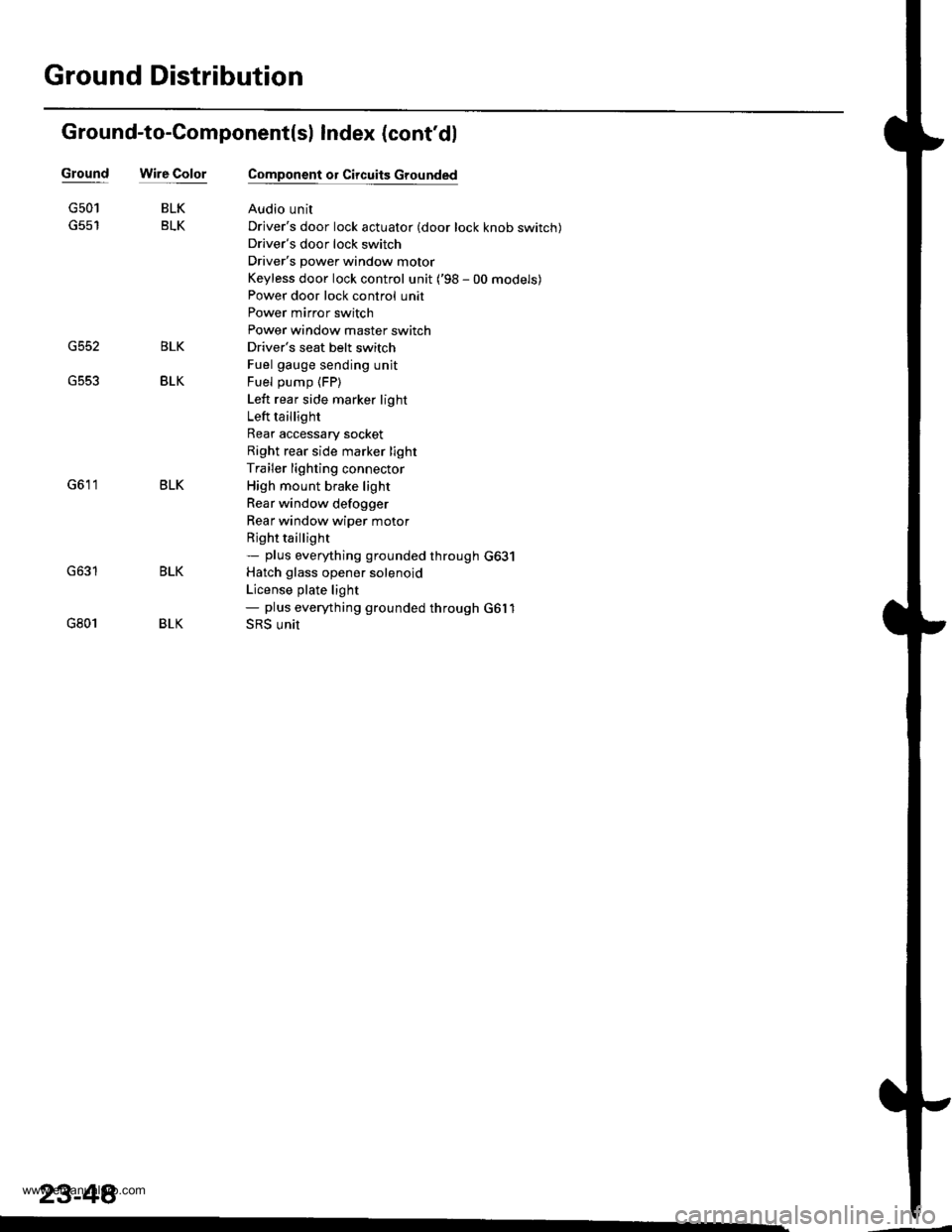
Ground Distribution
Ground-to-Component(sl Index (cont'dl
Wire ColorGround
G552
G501
G801
BLK
BLK
BLK
BLK
Component or Circuits Grounded
Audio unit
Driver's door lock actuator (door lock knob switch)
Driver's door lock switch
Driver's power window motor
Keyless door lock control unit ('98 - 00 models)
Power door lock control unit
Power mirror switch
Power window master switch
Driver's seat belt switch
Fuel gauge sending unit
Fuel pump (FP)
Left rear side marker light
Left taillight
Rear accessary socket
Right rear side marker light
Trailer lighting connector
High mount brake light
Rear window defogger
Rear window wiper motor
Rjght taillight- plus eveMhing grounded through G631
Hatch glass opener solenoid
License plate light- plus eveMhing grounded through G6l1
SRS unit
BLK
BLK
BLK
23-48�
www.emanualpro.com
Page 1220 of 1395
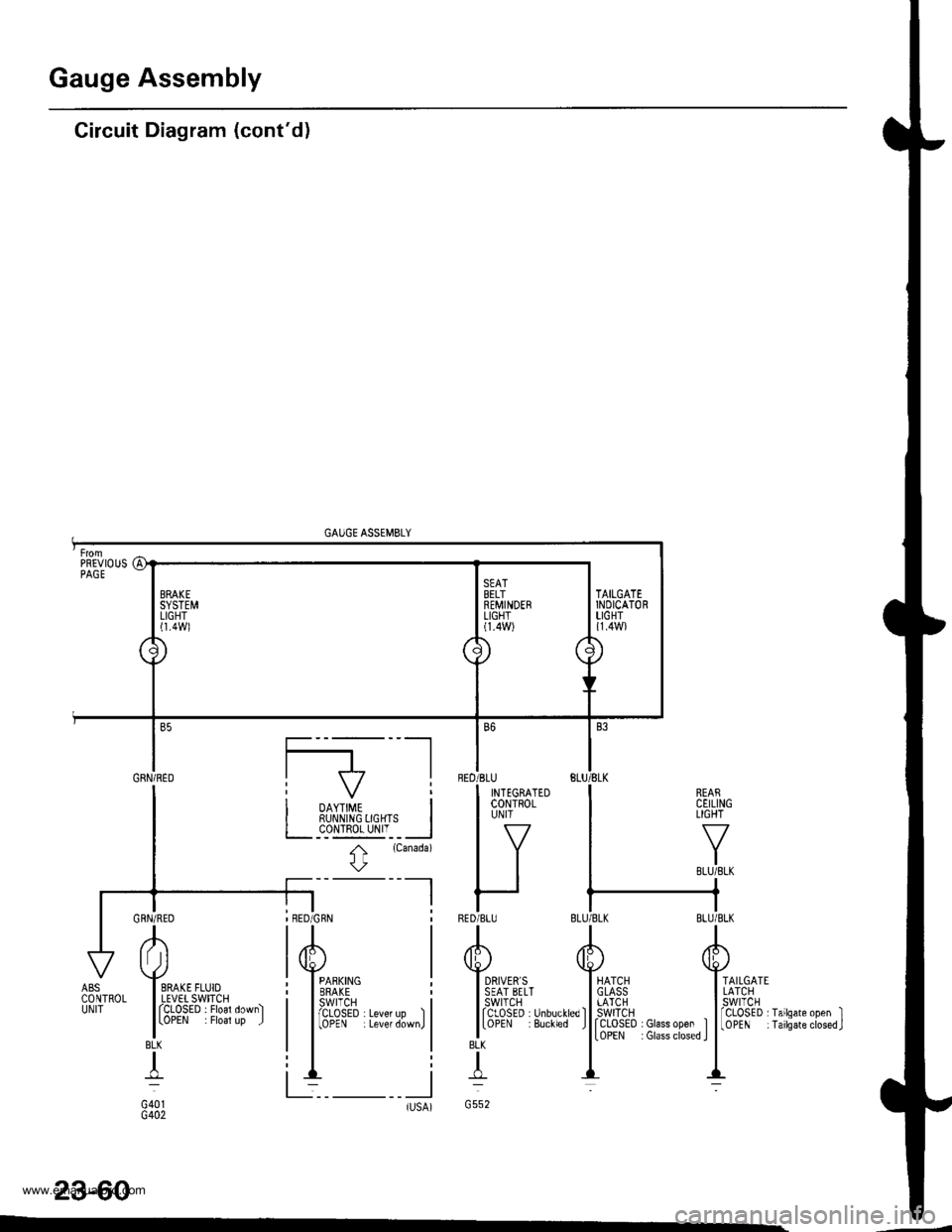
Gauge Assembly
Circuit Diagram (cont'd)
GAUGE ASSEMBLY
REARCEILINGLIGHT
TAILGATELATCHswtTcH
rCLOSED I Glass open ItoPEN : Glass closed I
fCLoSED rTailsate open II0PEN iTailsateclosed.J
23-60
BLK
T
G552tlsA)-
AI Jl
I SRAKE FLUIOI LEVET SWITCHI fCLOSED . Floal down)
lLoPEN . Floal up J
BLK
+
G401G402
ABSCONTROLUNIT
PREVIOUSPAGE
a1
\J
BRAKESYSTEMLIGHTl1.4Wl
\
./
SEATBELTREMINDERLIGHT(1.4W)
\/'
7\
\
TAILGATEINDICATORLIGHT{1.4W}
Gnru;neo I f7 |
I i oo,,#, i| | RUI\N|NG 0GHTS I
I L__c_o!l!g_yI'__l
I t
rcanada)
l\
-l I
BED
RED
B6
'BLU
I INTEGRATEDI coNTRoLI UN|T
lv
IItt
r-IBLU
www.emanualpro.com
Page 1242 of 1395
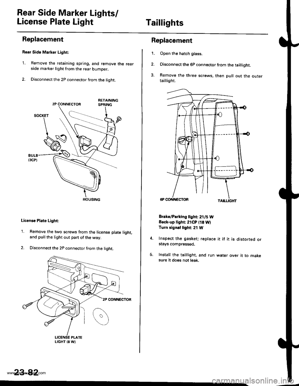
Rear Side Marker Lights/
License Plate LightTaillights
Replacement
Rear Side Marke. Light:
1. Remove the retaining spring, and remove the rearside marker light from the rear bumper.
2. Disconnect the 2P connector from the light.
RETAINING
HOUSING
Licens€ Plate Light:
1. Remove the two screws from the license plate light,and pull the light out part of the way.
2. Disconnect the 2P connector from the light,
23-A2
LIGHT (8 WI
Replacement
1. Open the hatch glass.
2. Disconnect the 6P connector from the taillight.
3. Remove the three screws, then pull out the outertaillight.
Brak€/Plrking light 2115 W
Back-up light: 21CP (18 W)
Turn signll light 21 W
Inspect the gasket; replace it if it is distorted or$ays compressed.
Install the taillight, and run water over it to makesure it does not leak.
www.emanualpro.com