Hydraulic HONDA CR-V 1998 RD1-RD3 / 1.G Owner's Guide
[x] Cancel search | Manufacturer: HONDA, Model Year: 1998, Model line: CR-V, Model: HONDA CR-V 1998 RD1-RD3 / 1.GPages: 1395, PDF Size: 35.62 MB
Page 551 of 1395
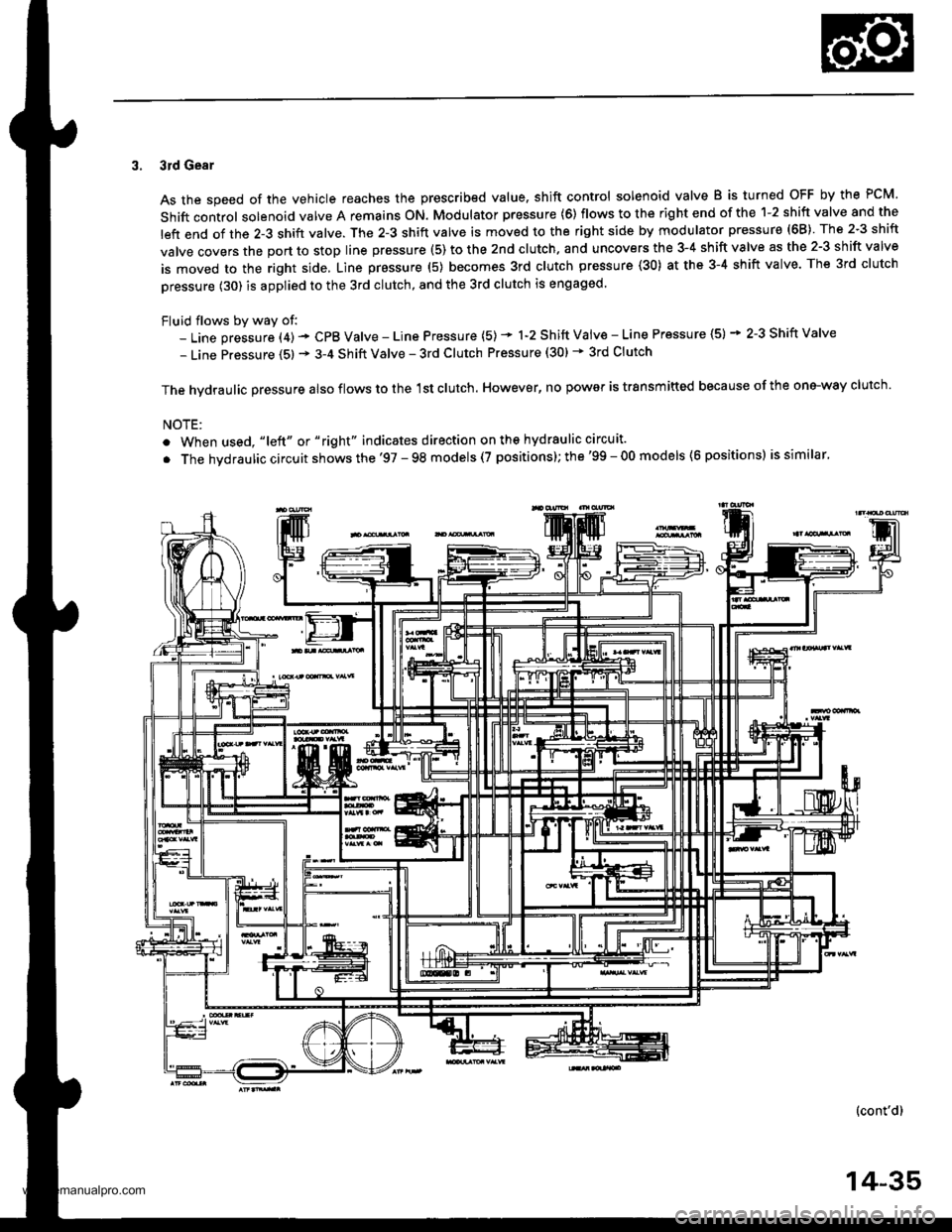
3. 3rd Gear
As the speed of the vehicle reaches the prescribed value. shift control solenoid valve B is turned OFF by the PCM.
Shift control solenoid valve A remains ON. Modulator pressure (6) flows to the right end of the 1-2 shift valve and the
left end of the 2-3 shift valve. The 2-3 shift valve is moved to the right side by modulator pressure (68) The 2-3 shift
valve covers the port to stop line prsssure (5) to the 2nd clutch. and uncovers the 3-4 shift valve as the 2-3 shift valve
is moved to the right side, Line pressure (5) becomes 3rd clutch pressure (30) at the 3-4 shift valve. The 3rd clutch
pressure (30) is applied to the 3rd clutch, and the 3rd clutch is engaged.
Fluid flows by way of:- Line pressure (4) - CPB Valve - Line Pressure (5) * 1-2 Shift Vaiv€ - Line Pressure (5) * 2-3 Shift Valve
- Line Pressure (5) * 3-4 Shift Valve - 3rd Clutch Pressure (30) * 3rd Clutch
The hvdraulic Dressure also flows to the 1st clutch. However, no power is trsnsmitted because of the one-way clutch.
NOTE:
. When used, "|eft" or "right" indicates direction on ths hydraulic circuit.
. The hvdraulic circuit shows the '97 - 98 models (7 positions); the'99 - 00 models (6 positions) is similar.
(cont'd)
14-35
www.emanualpro.com
Page 552 of 1395
Description
Hydraulic Flow (cont'd)
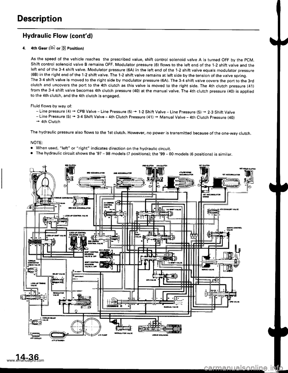
4th Gear llQ! or E Posirion)
As the speed of the vehicle reaches the prescribed value. shift control solenoid valve A is turned OFF by the pCM,
Shift control solenoid valve B remains OFF. Modulator pressure (6) flows to the left end of the 1-2 shift valve and theleft end of the 3-4 shift valve. Modulator pressure (64) in the left end of the 1-2 shift valve equals modulator pressure(68) in the right end of the 1-2 shift valve. The 1-2 shift valve remains at left side by the tension of the valve spring.The 3-4 shift valve is moved to the right side by modulator pressure (6A). The 3-4 shift valve covers the pon to the 3rdclutch and uncovers the port to the 4th clutch as this valve is moved to the right side, The 4th clutch pressure (41)from the 3-4 shift valve becomes 4th clutch pressure (40) at the manual valve. The 4th clutch pressure (40) is appliedto the 4th clutch, and the 4th clutch is engaged.
Fluid flows by way of:- Line pressure (4) + CPB Valve - Line Pressure (5) + l-2 Shift Valve - Line Pressure {5) * 2-3 Shift Valve- Line Pressure (5) + 3-4 Shift Valve - 4th Clutch Pressure (41) + Manual Valve - 4th Clutch Pressure (40)+ 4th Clutch
The hydraulic pressure also flows to the lst clutch. However, no power is transmitted because of the one-wav clutch.
NOTE:
. When used, "lelt" or " tight" indicates direction on the hydraulic circuit.. The hydrau lic circuit shows the '97 - 98 models (7 positions); the '99 - 0O models (6 oositions) issimilar.
14-36
www.emanualpro.com
Page 553 of 1395
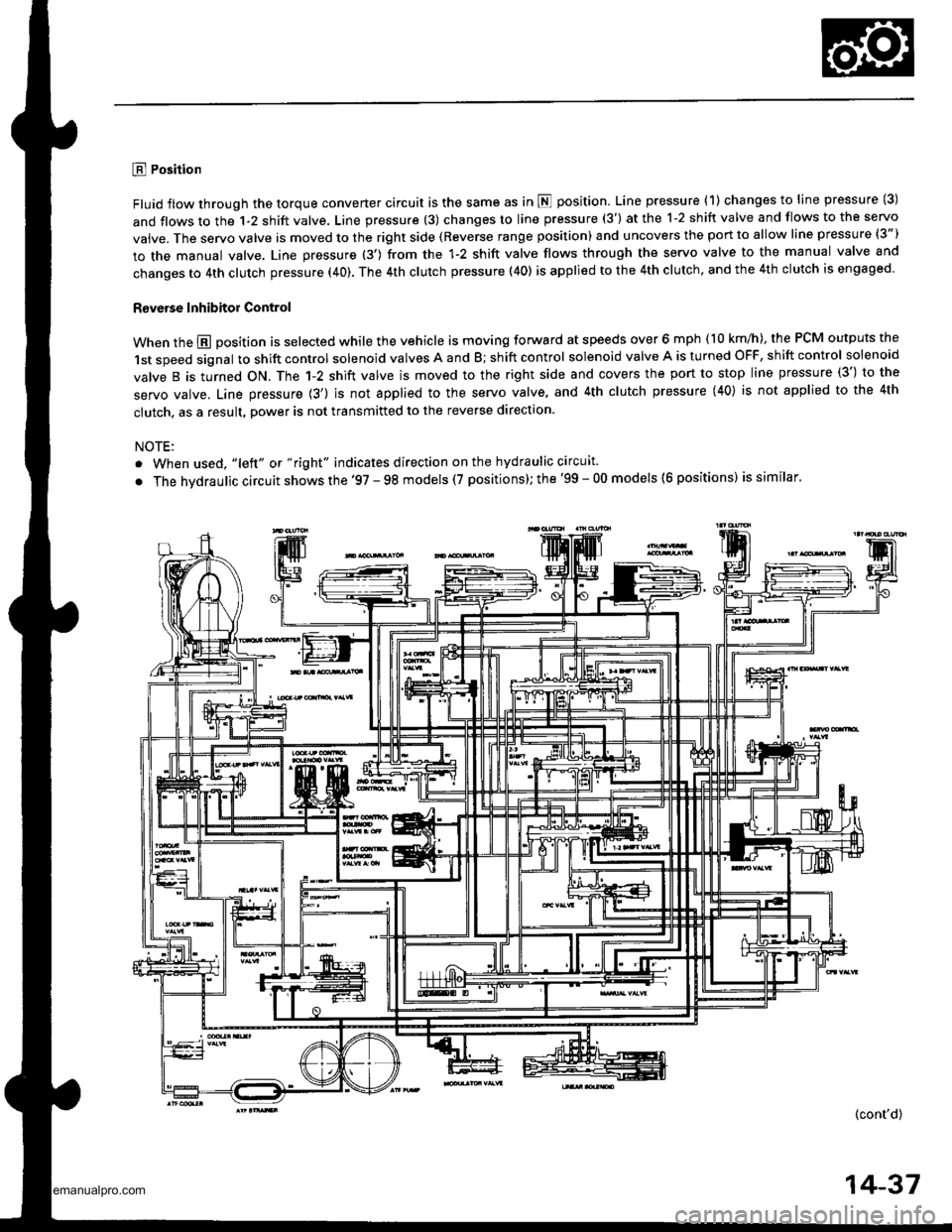
E Position
Fluid flow through the torque converter circuit is the same as in N position. Line pressure (1) changes to line pressure (3)
and flows to the 1-2 shift valve. Line pressure (3) changes to line pressure (3') at the 1-2 shift valve and flows to the servo
vaive. The servo valve is moved to the right side (Reverse range position) and uncovers the port to allow line pressure (3")
to the manual valve. Line pressure (3') from the 1-2 shift valve flows through the servo valve to the manual valve and
changes to 4th clutch pressure (40). The 4th clutch pressure (40) is applied to the 4th clutch, and the 4th clutch is engaged.
R€verse Inhibitor Control
When the @ position is selected while the vehicle is moving forward at speeds over 6 mph (10 km/h), the PCM outputs the
1st speed signal to shift control solenoid valves A and B; shift control solenoid valve A is turned OFF, shift control solenoid
valve B is turned ON. The 1-2 shift valve is moved to the right side and covers the port to stop line pressure (3') to the
servo valve. Line pressure {3') is not applied to the servo valve, and 4th clutch pressure (40} is not applied to the 4th
clutch, as a result, power is not transmitted to the reverse direction.
NOTE:
. When used, "lelt" ot " right" indicates direction on the hydraulic circuit.
. The hvdraulic circuit shows the '97 - 98 models (7 positions); the '99 - 00 models (6 positions) is similar'
(cont'd)
14-37
www.emanualpro.com
Page 554 of 1395
Description
Hydraulic Flow (cont'dl
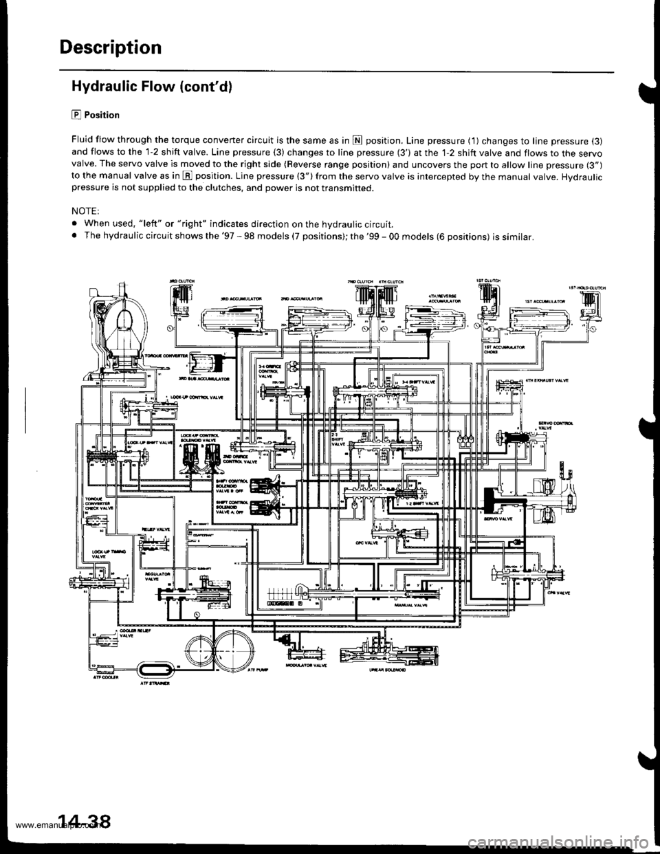
E Position
Fluid flow through the torque converter circuit is the same as in fl position. Line pressure ( 1) changes to line pressure (3)
and flows to the 1-2 shift valve. Line pressure (3) changes to line pressure {3') at the 1-2 shift valve and flows to the servovalve. The servo valve is moved to the right side (Reverse range position) and uncovers the port to allow line pressure (3")
to the manual valve as in E position. Line pressure (3") from the servo valve is intercepted by the manual valve. Hydraulicpressure is not supplied to the clutches, and power is not transmitted.
NOTE:
. When used, "left" or "right" indicates direction on the hydraulic circuit.. The hydraulic circuit shows the '97 - 98 models (7 positions); the '99 - 00 models (6 positions) issimilar.
14-38
www.emanualpro.com
Page 555 of 1395
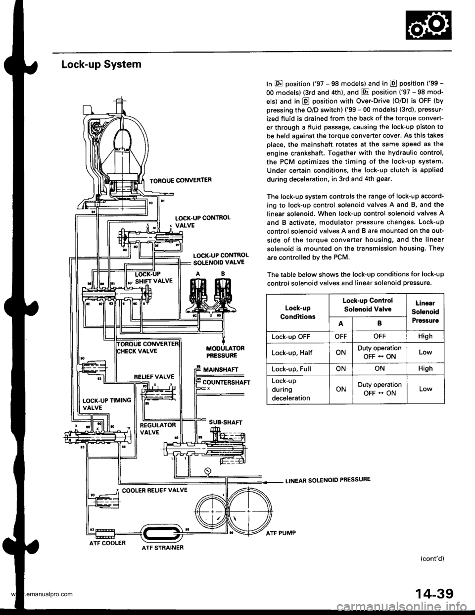
Lock-up System
TOROUE CONVERTER
In E position ('97 - 98 models) and in E position ('99 -
OO models) (3rd and 4th), and E position ('97 - 98 mod-
els) and in E position with Over-Drive (O/D) is OFF (by
pressing the O/D switch) ('99 - 00 models) (3rd), pressur-
ized fluid is drained from the back of the torque convert-
er through a fluid passage, causing the lock-up piston to
be held against the torque converter cover, As this takes
Dlace, the mainshaft rotates at the same speed as th8
engine crankshaft. Together with the hydraulic control,
the PCM optimizes the timing of the lock-up system.
Under certain condltions. the lock-up clutch is appli€d
during deceleration, in 3rd and 4th gear.
The lock-up system controls the range of lock-up sccord-
ing to lock-up control solenoid valves A and B, and ths
linear solenoid. When lock-up control solenoid valves A
and B activate. modulator pressure changes. Lock-up
control solenoid valves A and B are mounted on the out-
side of the torque converter housing, and the linear
solenoid is mounted on the transmission housing. They
are controlled bv the PCM.
The table below shows the lock-up conditions for lock-up
control solenoid valves and linear solenoid pressure.
LINEAR SOLENOID PRESSURE
(cont'd)
LOCK.UP CONTROL' VALVE
LOCK.UP CONTROLSOLENOID VALVE
AB
MODULATORPf,ESSURE
MAINSHAFT
COUNTERSHAFT
SUB.SHAFT
Lock-up
Conditions
Lock-up Conirol
Solenoid valveLinaal
Solenoid
PrgssulsAB
Lock-up OFFOFFOFFHigh
Lock-up, HalfONDuty operation
OFF - ONLow
Lock-up, FullONONHigh
Lock-up
during
deceleration
ONDuty operation
OFF - ON
RELIEF VALVE
LOCK'UP TIMINGVALVE
COOLER RELIEF VALVE
ATF COOLERATF STRAINER
ATF PUMP
14-39
www.emanualpro.com
Page 557 of 1395
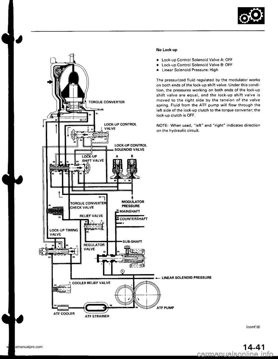
TOROUE CONVERTER
No Lock-up
. Lock-up Control Solenoid Valve A: OFF
. Lock-up Control Solenoid Valve B: OFF
. Linear Solenoid Pressure: High
The pressurized fluid regulated by the modulator works
on both ends of the lock-up shift valve. Under this condi-
tion, the pressures working on both ends of the lock-up
shift valve are equal. and the lock-up shift valve is
moved to the right side by the tension of the valve
spring. Fluid trom the ATF pump will flow through the
left side of the lock-up clutch to the torque converter; the
lock-up clutch is OFF.
NOTE: When us€d, "|eft" and "right" indicates direction
on the hydraulic circuit.
+ LINEAR SOLENOID PRESSURE
(cont'd)
LOCK.UP CONTROLSOI-ENOID VALVE
MOOULATORPRESSURE
MAINSHAFT
COUNTERSHAFTRELIEF VALVE
LOCK-UP TIMINGVALVE
i COOLER RELIEF VALVE
ATF STRAINERATF COOLER
ATF PUMP
14-41
www.emanualpro.com
Page 559 of 1395
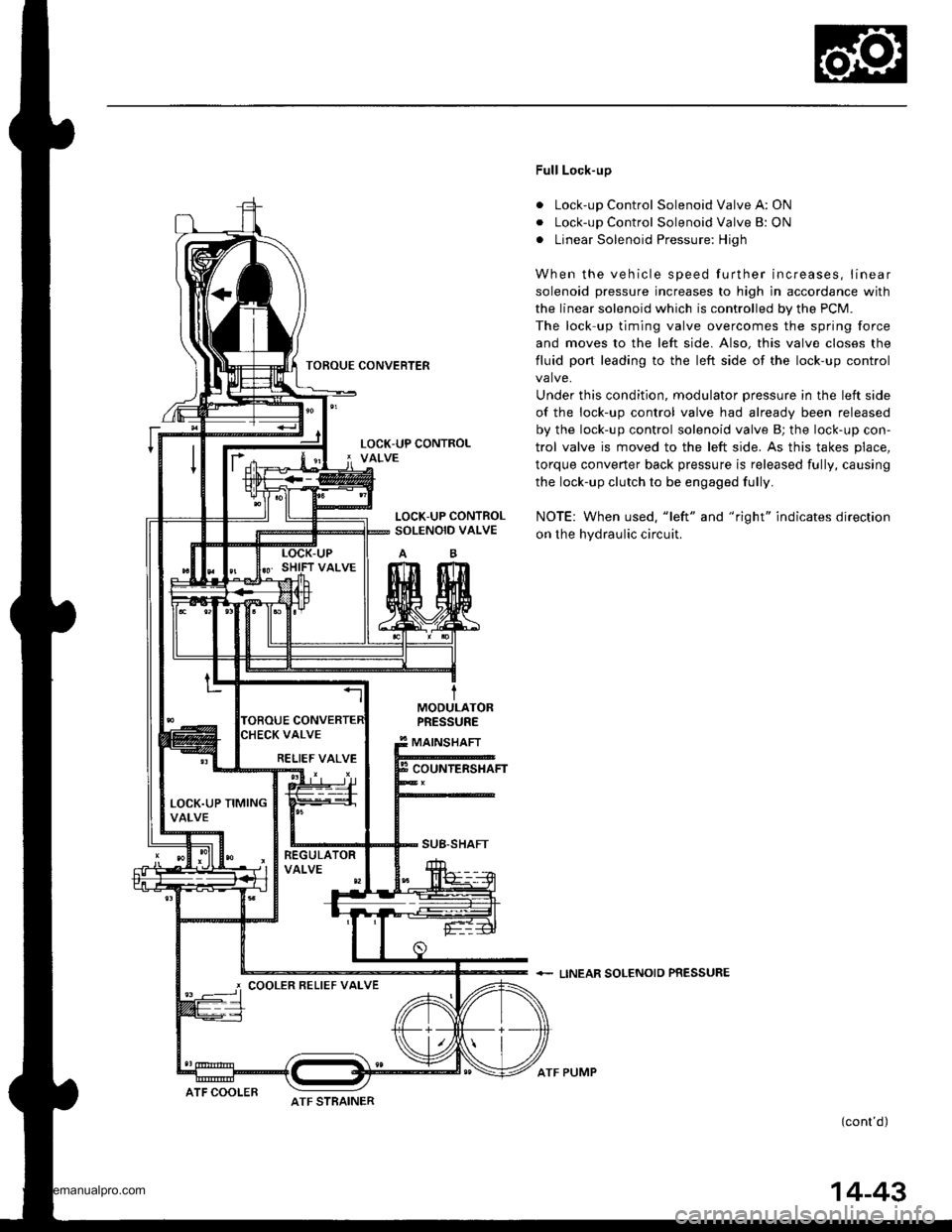
TOROUE CONVEFTER
Full Lock-up
. Lock-up Control Solenoid Valve A: ON
. Lock-up Control Solenoid Valve B: ON
. Linear Solenoid Pressure: High
When the vehicle speed further increases, linear
solenoid pressure increases to high in accordance with
the linear solenoid which is controlled by the PCM.
The lock up timing valve overcomes the spring force
and moves to the left side. Also, this valve closes the
fluid port leading to the left side of the lock-up control
valve.
Under this condition, modulator pressure in the left side
of the lock-up control valve had already been released
by the lock-up control solenoid valve B; the lock-up con-
trol valve is moved to the left side. As this takes place,
torque converter back pressure is released fully, causing
the lock-up clutch to be engaged fully.
NOTE: When used. "left" and "right" indicates direction
on the hydraulic circuit.
+ LINEAR SOLENOIO PRESSURE
(cont'd)
LOCK-UP CONTROLSOLENOID VALVE
MODULATORPRESSURE
MAINSHAFT
COUNTERSHAFT
SUB-SHAFT
RELIEF VALVE
LOCK.UP TIMINGVALVE
COOLER BELIEF VALVE
ATF STRAINERATF COOLER
ATF PUMP
14-43
www.emanualpro.com
Page 560 of 1395
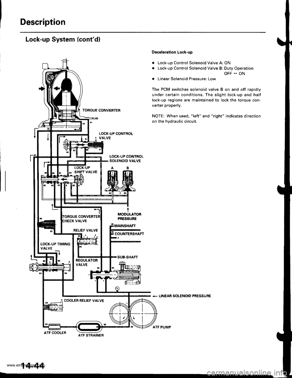
Description
Lock-up System (cont'dl
a
a
Decelelation Lock-up
Lock-up Control Solenoid Valve A: ON
Lock-up Control Solenoid Valve B; Duty Operation
OFF - ON
Linear Solenoid Pressure: Low
The PCM switches solenoid valve B on and off rapidly
under certain conditions. The slight lock-up and half
lock-up regions are maintained to lock the torque con-
vener propeny.
NOTE: When used, "left" and "right" indicates direction
on the hydraulic circuit.
+ LINEAR SOLENOID PRESSURE
TOROUE CONVERTER
tMOOULATORPRESSURE
MAINSHAFT
COUNTERSHAFT
SUB.SHAFT
ATF COOLER
RELIEF VALVE
LOCK.UP TIMINGVALVE
COOLER RELIEF VALVE
14-44
ATF STBAINER
ATF PUMP
www.emanualpro.com
Page 598 of 1395
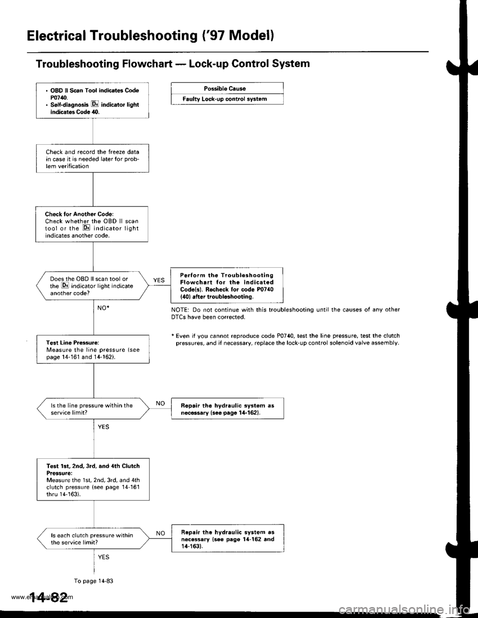
Electrical Troubleshooting ('97 Model)
. OBD ll Scan Tool indicrt6 Cod6P0740.. Self-diagno3b E indicator lightindicatos Codc 40.
Check and record the freeze datain case it is needed laterlor prob-
lem verification
Check tor Another Code:Check whether the OBD ll scantool or the E indicator lightindicates another code.
Perlorm the TroubleshootingFlowchart lor th€ indicat€dCodo{s). Rocheck tor code P0740
{ilol after troubl$hooting.
Does the OBD ll scan tool orthe E indicator light indicateanother code?
Tesl Line Pressure:Measure the line pressure (seepage 14-161 and 14-162).
ls the line pressure within theservice limit?R6pair tho hydraulic ayst€m asnecessary {see page 14-162}.
Test lst, 2nd, 3rd, and 4th ClutchPressure:Measure the 1st, 2nd, 3rd, and 4thclutch pressure (see page 14161thru 14''163).
Repair the hydraulic system dsnecessary {see pago 14-152 rnd14-163).
ls each clutch pressure withinthe service limit?
Troubleshooting Flowchart - Lock-up Control System
Possiblo Cause
Faulty Lock-up control sy3t6m
NOTE: Do not continue with this troubleshooting until the causes of any otherDTCS have been corrected.
* Even if yotl cannot reproduce code P0740. test the line pressure, test the clutchpressures, and i{ necessary, replace the lock-up control solenoid valve assembly
1
To page 14-83
4-82
www.emanualpro.com
Page 600 of 1395
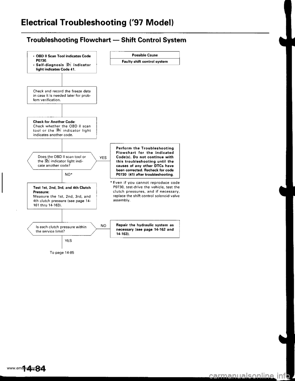
Electrical Troubleshooting ('97 Model)
Troubleshooting Flowchart - Shift Control System
Possible Cause
F""lty "t lft ".tttr"l "y"t..
+ Even it you cannot reproduce codeP0730, test drive the vehicle, test theclutch pressures, and if necessary,replace the shift control solenoid valve
. OBD ll Scan Tool indicates CodeP0730.. Selt-diagnosis E,l indicatorlight indicates Code 41.
Check and record the freeze datain case it is needed later for prob-lem verification.
Check tor Another Code:Check whether the OBD ll scantool or the Pll indicator lightindicates another code,
Pertorm the TroubleshootingFlowchart for the indicatedCodels). Do not conlinu€ withthis troubleshooting until thecauses of anv other DTCS havebeen corrected. Recheck for codeP0730 {41) after troubloshooting.
Does the OBD ll scan tool orthe E indicator light indi-cate another code?
Test lst. 2nd, 3rd. and 4th ClutchPressure:Measure the 1st, 2nd, 3rd, and4th clutch pressure (see page 14-161 thru 14-163).
Repair the hydraulic svstem asnecessary lsee page 1,1-162 andr4-1631.
ls each clutch pressure withinthe service limit?
To page 14-85
www.emanualpro.com