Hydraulic HONDA CR-V 1998 RD1-RD3 / 1.G Repair Manual
[x] Cancel search | Manufacturer: HONDA, Model Year: 1998, Model line: CR-V, Model: HONDA CR-V 1998 RD1-RD3 / 1.GPages: 1395, PDF Size: 35.62 MB
Page 884 of 1395
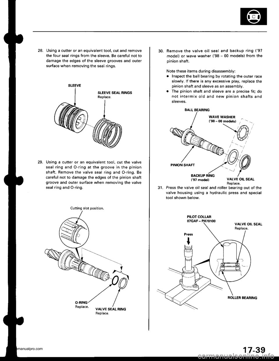
28. Using a cutte. or an equivalent tool, cut and remove
the four seal rings from the sleeve. Be careful not to
damage the edges ot the sleeve grooves and outer
surface when removing the seal rings.
Using a cutter or an equivalent tool. cut the valve
seal ring and O-ring at the groove in the pinion
shaft. Remove the valve seal ring and O-ring. Be
careful not to damage the edges of the pinion shaft
groove and outer surface when removing the valve
seal rjng and O-ring.
29.
SLEEVE
Cufting slot position.
30. Remove the valve oil seal and backup ring ('97
model) or wave washer ('98 - 00 models) from the
pinion shaft.
Note these items during disassembly:
. Inspect the ball bearing by rotating the outer race
slowly. lf there is any excessive play, replace the
pinion shaft and sleeve as an assembly.
. The pinion shaft and sleeve are a precise fit; do
not intermix old and new Dinion shafts and
sreeves,
WAVE WASHERl'98 - 0O modelsl
PINION SHAFT
BACKUP RING{'97 modellVALVE OIL SEAL
31.Replace.Press the valve oil seal and roller bearing out of the
valve housing using a hydraulic press and special
tool shown below.
BALL BEARING
PILOT COLLAR
ROLLER SEARING
www.emanualpro.com
Page 887 of 1395
Power Steering Gearbox
13.
Reassembly (cont'd)
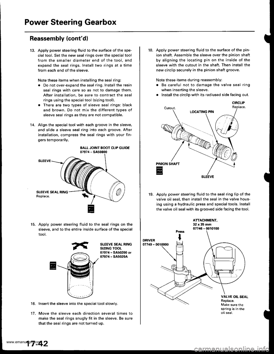
Apply power steering fluid to the surface of the spe-
cial tool. Set the new seal rings over the special tool
from the smaller diameter end of the tool. and
expand the seal rings. Install two rings at a time
Jrom each end ofthe sleeve.
Note these items when installing the seal ring:
. Do not over-expand the seal ring. Install the resin
seal rings with care so as not to damage them.
After installation, be sure to contract the seal
rings using the specialtool {sizing tool).
. There are two types of sleeve seal rings: black
and brown. Do not mix the different types of
sleeve seal rings as they are not compatible.
Align the special tool with each groove in the sleeve,
and slide a sleeve seal ring into each groove. After
installation, compress the seal rings with your fin-
gers temporarily.
BALL JOINT BOOT CLIP GUIDE07974 - SA508q)
SLEEVE
Apply power steering fluid to the seal rings on the
sleeve, and to the ehtire inside surface of the special
tool.
14.
15.
SLEEVE SEAL RINGSIZING TOOL07974 - SA502O0 or07974 - SA5020A
16.Insert the sleeve into the special tool slowly.
Move the sleeve each direction several times to
make the seal rings snugly fit in the sleeve. Be sure
that the seal rings are not turned up,
't1.
18. Apply power steering fluid to the surface of the pin-
ion shaft. Assemble the sleeve over the Dinion shaft
by aligning the locating pin on the inside of the
sleeve with the cutout in the shaft. Then install the
new circlip securely in the pinion shaft groove.
Note these items during reassembly:
. Be caretul not to damage the valve seal ring
when inserting the sleeve.
. Install the circlip with its radiused side facing out.
Apply power steering fluid to the seal ring lip of the
valve oil seal. then install the seal in the valve hous-
ing using a hydraulic press and special tools. Install
the valve oil seal with its grooved side facing the tool.
19.
ATTACHMENT,32x35mm077i16 - (x)10100
VALVE OIL SEALReplace.Make sure thespring is in theoilseal.
CIRCLIP
www.emanualpro.com
Page 888 of 1395
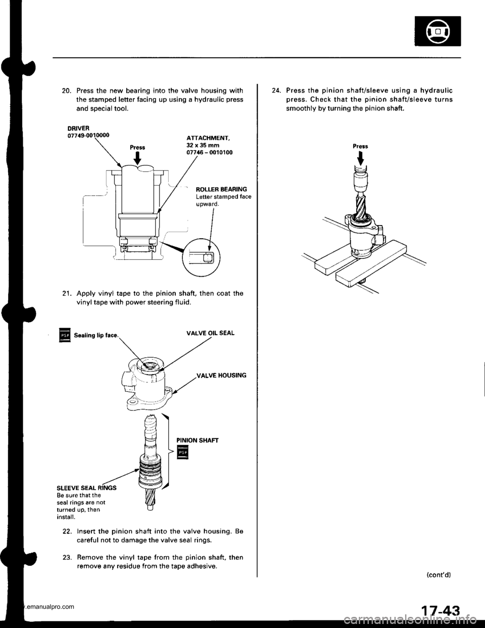
20. Press the new bearing into the valve housing with
the stamped letter facing up using a hydraulic press
and soecialtool.
ATTACHMENT,32x35mm07746 - 0010100
- ROLLER BEARINGLetter stamped face
21. Apply vinyl tape to the pinion shaft, then coat the
vinyltape with power steering fluid.
Sealing lip tace.VALVE OIL SEAL
VALVE HOUSING
SHAFT
SLEEVE SEAL
PINION
E
22, Insert the pinion shaft into the valve housing. Be
careful not to damage the valve seal rings.
23. Remove the vinyl tape from the pinion shaft, then
remove any residue from the tape adhesive.
8e sure that theseal rings are notturned up, theninstall.
DRIVER
24. Press the pinion shaft/sleeve using a hydraulic
press. Check that the pinion shaft/sleeve turns
smoothly by turning the pinion shaft,
(cont'd)
17-43
www.emanualpro.com
Page 911 of 1395
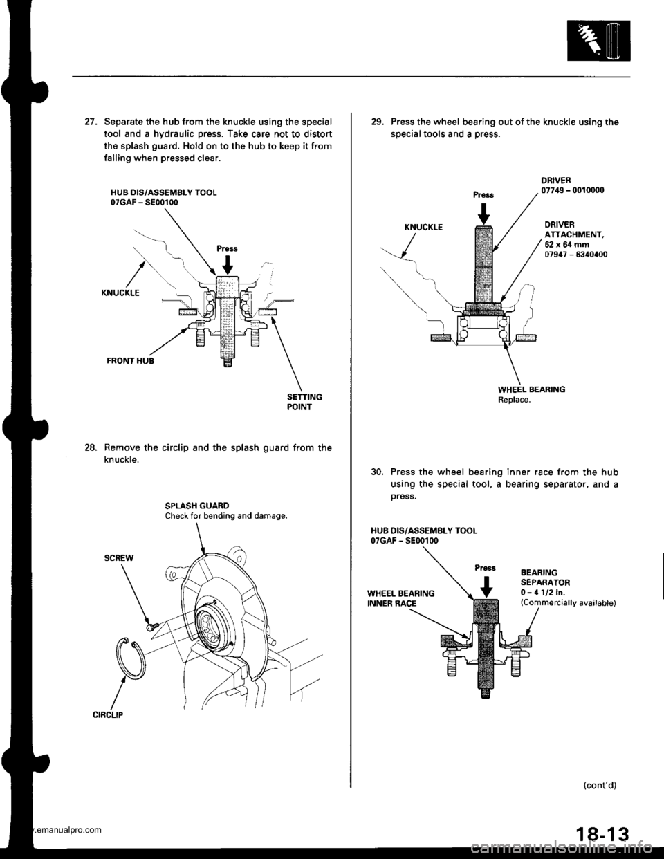
27. Separate the hub from the knuckle using the special
tool and a hydraulic press. Take care not to distort
the splash guard. Hold on to the hub to keep it from
falling when pressed clear.
HUB DIS/ASSEMELY TOOL07GAF - 5800100
FRONT HUB
SETTINGPOINT
Remove the circlip and the splash guard from the
knuckle.
28.
Check for bending and damage.
29. Press the wheel bea.ing outofthe knuckle using the
soecialtools and a Dress.
DRIVER077,19 - 0010000
ORIVERATTACHMENT,62x64mm07947 - 6340400
30. Press the wheel bearing inner race from the hub
using the special tool, a bearing separator, and a
press.
HU8 OIS/ASSEMBLY TOOL07GAF - SE00100
EEARINGSEPARATORO-1112in.(Commercially available)
{cont'd}
18-13
www.emanualpro.com
Page 912 of 1395
Front Suspension
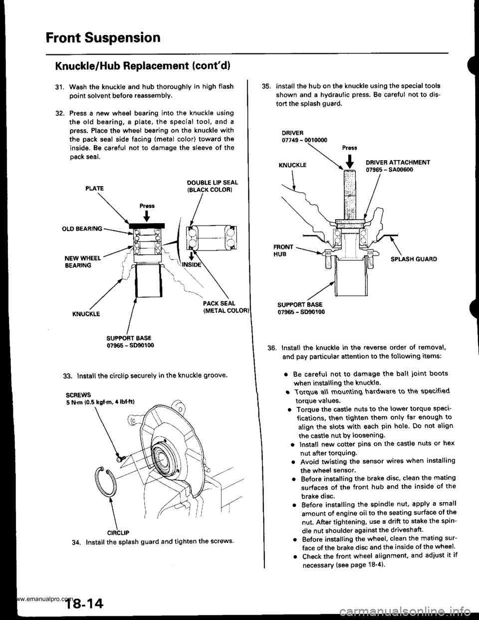
31.
Knuckle/Hub Replacement (cont'dl
Wash the knuckle and hub thoroughly in high flash
point solvent before reassembly,
Press a new wheel bearing into the knuckle using
the old b6aring, a plate. the special tool, and a
press. Place the wheel bearing on the knuckle with
the pack seal side facing (metal color) toward the
inside. Be careful not to damage the sleeve of the
Dack seal.
DOUBLE LIP SEALIBLACK COLORI
SUPPORT BASE0?965 - SD90t00
33. Install the circlip securely in the knuckle groove.
35. lnstall the hub on the knuckle using the specialtools
shown and a hydraulic press. Be careful not to dis-
tort the splash guard.
ORIVER077irg - 0010000
SPLASH GUARO
lnstall the knuckle in the reverse order of removal,
and pay particular attention to the following items:
. Be careful not to damage the ball joint boots
when installing the knuckle.
r Torque a\ mount
g hardv{are to ths speci{ied
torque values,
o Torque the castle nuts to the lower torque speci
fications, then tighten them only iat enough to
align the slots with each pin hole. Do not align
the castle nut by loosening.
a lnstall new cotter pins on the castle nuts or hex
nut after torquing.
. Avoid twisting the sensor wires when installing
the wheel sensor.
. Before installing the brake disc, clean the mating
surfaces of the front hub and the inside of the
brake disc.
. Before installing the spindle nut, apply a small
amount of engine oil to the seating surface oJ the
nut. After tightening, use a drift to stake the spin-
dle nut shoulder against the driveshaft.
. Before installing the wheel. clean the mating sur-
face of the brake disc and the inside of the wheel.
. Check the front wheel alignment, and adjust it if
necessary {see page 18-4).
scREws5 N.m 10.5 kgl m, 4 lbl'tt)
CIRCLIP
34. Install the splash guard and tight€n the screws.
18-14
www.emanualpro.com
Page 953 of 1395
Anti-lock Brake System (ABS)
Features/Gonstruction (cont'd)
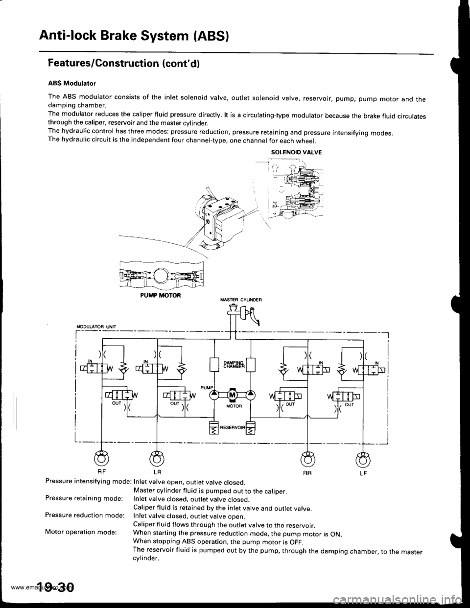
ABS Modulator
The ABS modulator consists of the inlet solenoid valve, outlet solenoid valve, reservoir, pump, pump motor and thedampjng chamber.
The modulator reduces the caliper fluid pressure directly. lt is a circulating-type modulator because the brake fluid circulatesthrough the caliper, reservoir and the master cylinder.The hydraulic control has three modes: pressure reduction, pressure retaining and pressure intensifying modes.The hydraulic circuit is the independent four channel-type, one channel for each wheel.
SOLENOID VALVE
t-
Pressure intensifying mode: Inlet valve open, outlet valve closed,
Pressure retaining mode:
Pressure reduction mode:
Motor operation mode:
Master cylinder fluid is pumped out to the caliper.Inlet valve closed, outlet valve closed.
Caliper fluid is retained by the inlet valve and outlet valve.Inlet valve closed, outlet valve ooen
Caliper fluid flows through the outlet valve to the reservoir.When starting the pressure reduction mode. the pump motor is ON.When stopping ABS operation, the pump motor is OFF.The reservoir fluid is pumped out by the pump, through the damping chamber, to the mastercylinder.
PUMP MOTOR
19-30
www.emanualpro.com